Sign In
Upload
Manuals
Brands
Ricoh Manuals
All in One Printer
Aficio MP 4002SP
Ricoh Aficio MP 4002SP Manuals
Manuals and User Guides for Ricoh Aficio MP 4002SP. We have
3
Ricoh Aficio MP 4002SP manuals available for free PDF download: Service Manual, User Manual, Manual
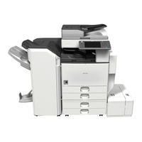
Ricoh Aficio MP 4002SP Service Manual (1402 pages)
Brand:
Ricoh
| Category:
All in One Printer
| Size: 20.62 MB
Table of Contents
Table of Contents
5
Laser Safety
17
Product Information
19
Specifications
21
Machine Configuration
22
Copier
22
Guidance for those Who Are Familiar with Predecessor Products
25
Overview
26
Component Layout
26
Paper Path
28
Drive Layout
29
Installation
31
Installation Requirements
33
Environment
34
Machine Level
34
Minimum Space Requirements
35
Power Requirements
35
Installation Flow Chart
36
Main Machine Installation
37
Accessory Check
37
Installation Procedure
39
Preliminary Procedures
39
PCDU (Photoconductor and Development Unit)
42
Paper Trays
45
Toner Bottle
45
Electrical Total Counter
46
Initialize TD Sensor and Developer
46
Set Paper Size for Paper Trays
46
Exposure Glass Cleaner
47
Settings Relevant to the Service Contract
47
Data Overwrite Security
48
HDD Encryption
49
App 2 Me Setting (SP Model Only)
50
Moving the Machine
51
Transporting the Machine
51
Paper Feed Unit Installation (D580)
52
Accessory Check
52
Installation Procedure
52
2000-Sheet Lct Installation (D581)
55
Accessory Check
55
Installation Procedure
55
1200-Sheet Lct Installation (D631)
58
Component Check
58
Installation Procedure
59
Ardf Installation (D630)
61
Component Check
61
Installation Procedure
61
1-Bin Tray Unit Installation (D632)
65
Component Check
65
Installation Procedure
66
Bridge Unit Installation (D634)
68
Component Check
68
Installation Procedure
69
3000/2000-Sheet (Booklet) Finisher (D636/D637)
73
Accessory Check
73
Installation Procedure
74
Support Tray Installation
77
Punch Unit Installation (D570)
78
Component Check
78
Installation Procedure
79
Platen Cover (D593)
84
1000-Sheet Finisher (D588)
85
Accessory Check
85
Installation Procedure
86
Side Tray (D635)
89
Component Check
89
Installation Procedure
90
Internal Shift Tray (D633)
94
Component Check
94
Installation Procedure
94
Key Counter Installation
96
Installation Procedure
96
Key Counter Interface Unit Installation
98
Installation Procedure
98
Tray Heater
100
Installation Procedure
100
Tray Heater (Optional Paper Feed Unit)
100
Component Check
102
Tray Heater (Optional Paper Feed Unit)
102
For Installing the Tray Heater in the D580 (Two-Tray Paper Feed Unit)
103
Installation Procedure
103
For Installing the Tray Heater in the D581 (LCT)
105
Hdd Installation (D640-11)
108
Component Check
108
Installation Procedure
109
After Installing the HDD
110
Copy Data Security Unit (B829)
111
Component Check
111
Installation Procedure
112
User Tool Setting
113
Check All Connections
114
Browser Unit Type I
115
Installation Procedure
115
Update Procedure
119
Card Reader Bracket Type C3352 (D593)
124
Component Check
124
Installation Procedure
126
Fax Connection Unit Type a (D629-31) (Remote Fax)
126
Preventive Maintenance
135
Pm Tables
137
Replacement and Adjustment
139
General Cautions
141
Laser Unit
141
Used Toner
141
Special Tools and Lubricants
142
Lubricants
142
Special Tools
142
Exterior Covers
143
Front Door, Upper and Lower Inner Cover
143
Lower Inner Cover
143
Upper Inner Cover
143
Left Cover
144
Rear Cover
144
Right Rear Cover
145
Front Right Cover
146
Operation Panel & Lcd
146
Paper Exit Cover
150
Inner Tray
151
Scanner
152
Exposure Glass
152
Operation Panel
152
Scanner Exterior Panels and Operation Panel
152
Scanner Left Cover
152
Scanner Front Cover
153
Scanner Rear Cover
153
Scanner Right Cover
153
Lens Block Assembly
154
Original Size Sensor
155
When Reassembling
155
Exposure Lamp
157
Chromaticity Rank Adjustment
158
Scanner HP Sensor
160
Scanner Hp Sensor/Platen Cover Sensor
160
Platen Cover Sensor
161
Scanner Motor
162
Front Scanner Wire
164
Scanner Motor Drive Board
164
Reassembling the Front Scanner Wire
166
Rear Scanner Wire
169
Reassembling the Rear Scanner Wire
170
Laser Unit
171
Caution Decal Locations
171
Laser Synchronization Detector
173
Polygon Mirror Motor
173
Laser Beam Pitch Adjustment
174
Ld Unit
174
Pcdu
177
Pcdu (Photoconductor and Development Unit)
177
Reinstallation
177
Drum
178
Re-Installation
179
Pick-Off Pawl Position Adjustment
180
Pick-Off Pawls
180
Charge Roller and Cleaning Roller
181
Drum Cleaning Blade
182
Re-Installation
182
ID Sensor
183
Development
184
Development Filter
184
Development Roller
184
Cleaning Procedure
185
Developer
186
Td Sensor
189
Transfer
190
Transfer Belt Unit
190
Transfer Belt
191
Toner Overflow Sensor
193
Transfer Belt Cleaning Blade
193
Transfer Belt Cleaning Blade/Toner Overflow Sensor
193
Toner Overflow Sensor
194
Paper Feed
195
Paper Feed Unit
195
Tray 1 and Tray 2
195
Pick-Up, Feed and Separation Rollers
196
Tray 1 and Tray 2
196
Tray Lift Motor
197
Relay, Tray Lift, Paper End and Paper Feed Sensors
198
Tray 1 and Tray 2
198
Registration Sensor
199
Reinstall the Registration Sensor
200
Fusing
201
Fusing Unit
201
Brake Pad
202
Web Roller Unit
202
Web Holder Roller and Web Rollers
203
Installing a New Web Holder Roller
205
Installing New Web Rollers
205
Pressure Roller Cleaning Roller
206
Thermostats
207
Thermistor
208
Hot Roller Strippers
209
Fusing Lamps
210
Hot Roller and Pressure Roller
211
Paper Exit
212
Fusing Exit, Paper Overflow, and Paper Exit Sensors
213
Junction Jam Sensor
213
Paper Exit Unit
213
Paper Exit Motor
214
Duplex
215
Duplex Unit
215
Duplex Door Sensor
217
Right Door Cover
217
Duplex Entrance Sensor
218
Duplex Exit Sensor
219
Duplex/By-Pass Motor
221
Duplex Inverter Motor
222
By-Pass
224
By-Pass Paper Size Sensor/By-Pass Paper Length Sensor
224
When Reinstalling the By-Pass Paper Size Sensor
226
By-Pass Paper End Sensor
227
By-Pass Pick-Up, Feed and Separation Roller, Torque Limiter
227
By-Pass Feed Clutch
228
Drive Area
229
Paper Feed Clutch
229
Tray 1 and Tray 2
229
Development Paddle Motor
230
Transfer/Development Motor
230
Drum Motor
231
Fusing Motor
231
Paper Feed Motor
232
Web Motor
232
Registration Motor
233
Transfer Belt Contact Motor
233
Toner Supply Motor
234
Electrical Components
235
Controller Unit
235
Before Replacing the HDD Unit
236
Hdd Unit
236
Replacement Procedure
236
After Installing the New HDD Unit
237
Before Replacing the Controller Board in the Model Without HDD
238
Controller Board
238
Replacement Procedure
238
When Installing the New Controller Board
240
After Installing the Controller Board
241
Mother Board
241
Bcu
243
Ipu
244
When Installing the New BCU
244
Iob
245
Psu
245
When Installing a New IOB
245
Fusing Exhaust Fan
246
High Voltage Power Supply
246
When Installing the Fusing Exhaust Fan
246
Controller Fan
247
When Installing the Controller Fan
247
Nvram on the Bcu Board
248
Replacement Procedure for the NVRAM on the BCU Board
248
Copy Adjustments: Printing/Scanning
249
Overview
249
Printing
249
Registration - Leading Edge/Side-To-Side
249
Scanning 4
250
Blank Margin
251
Main Scan Magnification
252
Parallelogram Image Adjustment
252
Registration: Platen Mode
254
Magnification
255
Adf 4
256
Touch Screen Calibration
257
Service Tables
258
Service Program Mode
260
Service Mode Lock/Unlock
260
Service Program Mode Operation
260
Service Tables 5
260
Service Program Mode Tables
261
Service Table Key
261
Service Program Mode Tables
262
Sp Tables
262
Main Sp Tables-1 5
263
Main Sp Tables-1
264
Main Sp Tables-2
272
Sp2-XXX: Drum
272
Main Sp Tables-3
277
Sp3-XXX: Process
277
Main Sp Tables-4
278
Sp4-XXX: Scanner
278
Main Sp Tables-5
300
Sp5-XXX: Mode
300
Main Sp Tables-6
367
Sp6-XXX: Peripherals
367
Main Sp Tables-7
367
Main Sp Tables-7 5
376
Sp7-XXX: Data Log
376
Main Sp Tables-8 5
391
Main Sp Tables-8
392
Main Sp Tables-9
442
Copier
442
Input Check Table
442
APS Original Size Detection
448
3000/2000-Sheet (Booklet) Finisher (D636/D637)
449
1000-Sheet Finisher (D588)
452
Copier
453
Output Check Table
453
1000-Sheet Finisher (D588)
458
3000 /2000-Sheet (Booklet) Finisher (D636/D637)
459
Printer Service Tables
461
SP1-XXX (Service Mode)
461
Scanner Service Tables
469
SP1-XXX (System and Others)
469
SP2-XXX (Scanning-Image Quality)
470
Updating the Firmware
471
Before You Begin
471
Preparation
472
Updating Firmware
472
Updating Procedure
472
Error Messages
474
Firmware Update Error
474
Recovery after Power Loss
474
Error Message Table
475
Handling Firmware Update Errors
475
Uploading/Downloading Nvram Data
477
Uploading Nvram Data (Sp5-824)
477
Downloading Nvram Data (Sp5-825)
478
Self-Diagnostic Mode
480
Self-Diagnostic Mode at Power on
480
Self-Diagnostic Test Flow
481
Detailed Self-Diagnostic Mode
482
Executing Detailed Self-Diagnosis
482
Using the Debug Log
483
Overview
483
Switching on and Setting up Save Debug Log
483
4-Digit Entries for Keys 1 to 10
485
Troubleshooting 6
485
Key to Acronyms
486
Recording Errors Manually
487
Retrieving the Debug Log from the HDD
487
Troubleshooting
488
Service Call Conditions 6
490
Sc Code Descriptions
491
SC Tables: Sc1Xx
492
SC Tables: Sc2Xx
495
SC Tables: Sc3Xx
497
SC Tables: Sc4Xx
500
SC Tables: Sc5Xx
501
SC Tables: Sc6Xx
510
SC Tables: Sc7Xx
519
SC Tables: Sc8Xx
531
SC Tables: Sc9Xx
554
Electrical Component Defects
560
Sensors
560
Switches
564
Blown Fuse Conditions
565
Fuses
566
D129/D130 Appendices
569
Appendix: General Specifications
573
General Specifications
573
General
573
Power Consumption
576
Printer Controller
577
Scanner Specifications
579
Optional Equipment
580
Ardf (D630)
580
Lct 2000-Sheet (D581)
581
Two-Tray Paper Feed Unit (D580)
581
1-Bin Tray Unit (D632)
582
Lct 1200-Sheet (D631)
582
Internal Shift Tray (D633)
583
Side Tray (D635)
583
1000-Sheet Finisher (D588)
584
Bridge Unit (D634)
584
Upper Tray
584
Lower Tray
585
3000-Sheet Finisher (D636)
586
2000-Sheet Booklet Finisher (D637)
588
Punch Unit for 2000/3000-Sheet (Booklet) Finisher1-18
590
Preventive Maintenance Tables
591
Appendix: Pm Tables
593
Pm Tables
593
Mainframe
593
Options
597
Ardf
598
Pfu
598
Lct
599
2000/3000-Sheet (Booklet) Finisher
600
Exporting Device Information
891
Importing Device Information
893
1000-Sheet Finisher B408/D588
896
1 Replacement and Adjustment
898
Main Pcb
898
Stapler Unit
899
Motors
900
Shift Motor
900
Stapler Motor
900
Lower Transport Motor
901
Upper Transport Motor and Exit Motor
901
Motors and Sensors
902
Preparation
902
Stack Height Sensor
903
Stapler Tray Paper Sensor
903
Lower Tray Lift Motor
904
2 Troubleshooting
905
Jam Detection
905
3 Service Tables
906
Dip Switch Settings
906
4 Detailed Descriptions
907
General Layout
907
Electrical Component Layout
908
Electrical Component Description
910
Drive Layout
912
Junction Gates
913
Sort/Stack Mode
913
Staple Mode
913
Upper Tray Mode
913
Upper Tray
914
Lower Tray Up/Down Mechanisms
915
Paper Shift Mechanism
916
Jogger Unit Paper Positioning Mechanism
917
Exit Guide Plate
918
Stapler Mechanism
919
Stapler Unit Movement Mechanism
920
Paper Feed-Out Mechanism
921
Ardf Df3010/Df3070 (B802/D630)
924
1 Replacement and Adjustment
928
Covers and Tray
928
Original Tray
929
Document Feed Components
930
Pick-Up Roller
930
Feed Belt
931
Separation Roller
933
Electrical Components
934
Df Drive Board
934
Original Length Sensors and Trailing Edge Sensor
935
Original Set, Separation, Skew Correction and Scanning Entrance Sensor
936
Original Width Sensors
937
Registration Sensor
937
Original Exit Sensor
938
Cover Sensor
939
Df Position Sensor
939
Pick-Up Roller Hp and Original Stopper Hp Sensor
940
Stamp Solenoid
941
Original Feed Drive
943
Adf Feed Motor
943
Adf Inverter Motor
944
Adf Transport Motor
944
Adf Pick-Up Motor
945
2 Detailed Descriptions
946
Component Layout
946
Mechanical Component Layout
946
Electrical Component Layout
947
Sensors and Drive Components
947
Electrical Component Descriptions
948
Drive Layout
950
Basic Operation
952
Original Size Detection
952
Mixed Original Size Mode
954
Skew Correction
956
Slip Detection
957
Original Transport and Exit
958
Dip Switches
961
Bridge Unit Bu3030/Bu3060 (D386/D634)
964
1 Replacement and Adjustment
968
Bridge Unit Control Board
968
Bridge Unit Drive Motor
969
Tray Exit Sensor
970
Relay Sensor
971
2 Details
972
Mechanical Component Layout
972
Drive Layout
973
Electrical Component Layout
974
Electrical Component Description
975
Junction Gate Mechanism
976
Paper Feed Unit (D537/D580)
979
Exterior Cover
981
Rear Cover
981
Replacement and Adjustment
981
Electrical Components
982
Lift Motors
982
Upper and Lower Paper Feed Clutches
983
Paper Feed Motor
984
Main Board
984
Feed
985
Paper Feed Unit
985
Pick-Up, Paper Feed and Separation Rollers
986
Lift, Paper End, and Relay Sensors
987
Large Capacity Tray
988
Large Capacity Tray (D538/D581)
990
Exterior Cover
992
Left and Right Tray
992
Changing the Tray Size
993
Replacement and Adjustment
992
Electrical Components
994
Paper Height Sensors on Paper Storage Side
994
Tray Lift Motor
995
Tray Motor
996
Main Board
996
Stack Transport Clutch
997
Feed
998
Paper Feed Unit
998
Pick-Up, Feed and Separation Rollers
999
Paper Feed, Paper End, Lift and Relay Sensors
1000
Side Tray Type C5501/C5502 (D542/D635)
1003
Trays and Covers
1006
Sub and Main Output Trays
1006
Tray Left Front and Rear Covers
1006
Electrical Components
1007
Side Tray Control Board
1007
Side Tray Drive Motor
1008
Side Tray Relay Sensor
1009
Side Tray Exit Sensor
1010
Fax Option Type
1011
Fax Option Type 5002 (D629)
1013
1 Installation
1019
Fax Option Installation
1019
Component Check
1019
Fax Option Installation Procedure
1020
G3 Interface Board Installation
1023
Component Check
1023
Installation: One G3 Board
1024
Installation: Two G3 Boards
1026
Fax Unit Options
1028
Memory Unit (G578)
1028
Handset (D645)
1029
2 Replacement and Adjustment
1031
Fcu
1031
Sram Data Transfer Procedure
1031
3 Troubleshooting
1037
Error Codes
1037
Ifax Troubleshooting
1059
Ip-Fax Troubleshooting
1062
Cannot Send by IP Address/Host Name
1062
Ip-Fax Transmission
1062
Cannot Send Via Voip Gateway
1064
Cannot Send by Alias Fax Number
1065
Cannot Receive Via IP Address/Host Name
1067
Ip-Fax Reception
1067
Cannot Receive by Voip Gateway
1068
Cannot Receive by Alias Fax Number
1069
4 Service Tables
1071
Cautions
1071
Service Program Tables
1072
Sp1-XXX (Bit Switches)
1072
Printer Switches
1109
Communication Switches
1117
G4 Internal Switches
1148
G4 Parameter Switches
1148
Ip Fax Switches
1149
Ncu Parameters
1158
Dedicated Transmission Parameters
1173
Programming Procedure
1173
Service Ram Addresses
1182
Sg3 Board
1196
Video Data Path
1198
Fax Communication Features
1201
Document Server
1202
Internet Mail Communication
1203
Capabilities of Programmable Items
1217
Ifax Specifications
1219
Fax Unit Configuration
1222
Rt3020 - 1200-Sheet Lct (D631)
1225
1 Replacement and Adjustment
1229
Covers
1229
Rear Cover
1229
Right Door
1229
Front and Top Covers
1230
Paper Feed
1231
Pick-Up, Paper Feed and Separation Rollers
1231
Drive
1232
Paper Feed Clutch
1232
Paper Feed Motor
1232
Tray Lift Motor
1233
Electrical Components
1234
Lct Set Switches
1234
Main Board
1234
Down Switch
1235
Front
1235
Paper Feed, Paper End, Tray Lift and Relay Sensors
1236
Stack Sensor
1237
Side Fence Position Change
1238
2 Details
1239
Component Layout
1239
Electrical Component Layout
1240
Electrical Component Descriptions
1241
Paper Feed
1241
Paper Feed Mechanism
1244
Tray Lift Mechanism
1245
Tray Lifting Conditions
1245
Tray Lowering Conditions (Full-Down Position)
1245
Tray Lowering Conditions (Paper Supply Position)
1245
Paper Height and End Detection
1246
Booklet Finisher Sr3020 (B803)/ Sr3110 (D637)/Sr4020 (D373) Finisher Sr3030 (B805)/
1267
Covers
1273
Exterior Covers
1273
Upper Tray, End Fence
1274
Replacement and Adjustment
1273
Main Unit
1275
Upper Tray Limit Sensor, Limit Switch
1275
Positioning Roller
1276
Proof Tray Exit Sensor
1277
Upper Tray Height Sensors
1277
Exit Guide Plate, Upper Tray Exit Sensor
1278
Proof Tray Full Sensor
1279
Finisher Entrance Sensor
1279
Pre-Stack Tray Exit Sensor
1280
Stapler Unit
1281
Corner Stapler
1281
Positioning Roller
1282
Fold Unit
1283
Fold Unit Entrance Sensor
1285
Fold Unit Exit Sensor
1286
Stack Present Sensor
1287
Folding Horizontal Skew Adjustment (for B804 Only)
1288
Fold Vertical Skew Adjustment (for B804 Only)
1291
Booklet Stapler Unit
1293
Booklet Stapler
1293
Booklet Stapler Motor
1294
To Reattach the Booklet Stapler Motor
1295
Summary of Electrical Components
1303
Proof Mode
1314
Shift Mode
1314
Tray Movement Mechanism
1318
Stapler Movement
1324
Booklet Pressure Mechanism
1326
Booklet Stapling and Folding
1327
Booklet Stapling and Folding Mechanisms
1333
Feed out
1336
Upper Tray Output
1336
Feed out Stacking
1337
Overview of Operation
1338
Punch Mechanisms
1341
Punch Hopper Mechanism
1344
Finisher Jam Detection
1345
Printer/Scanner Unit Type 5002 (D641)
1349
Installation
1353
Overview
1353
Printer/Scanner Options
1353
Other Options
1354
Board, Sd Card Slots
1355
Board Slot
1356
SD Card Slot
1358
USB Slots
1358
Printer and P/S Options (Basic Models)
1359
Overview
1359
Three Main Units
1359
Common Accessory Table
1360
Kit Contents
1360
Printer/Scanner Installation
1361
Scanner Enhance Option
1364
Accessory Check
1364
Installation (Application Merge)
1364
Important Notes about SD Cards
1365
To Undo an Option Update
1365
Application Merge
1366
If more than One Application Is Required
1366
Installing Controller Options
1367
Overview
1367
Board Slot
1367
SD Card Slots
1367
USB Slots
1367
Postscript 3 Unit (D641)
1368
File Format Converter (D377)
1369
Ieee 1284 Interface Board (B679)
1370
Printer Specifications
1396
Usb Specifications
1398
Bluetooth Specifications
1399
Printer Drivers
1400
Scanner and Lan Fax Drivers
1400
Software Accessories
1400
Utility Software
1401
Advertisement
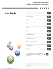
Ricoh Aficio MP 4002SP User Manual (228 pages)
User Guide
Brand:
Ricoh
| Category:
All in One Printer
| Size: 5.52 MB
Table of Contents
Table of Contents
3
How to Read the Manuals
8
Symbols Used in the Manuals
8
Model-Specific Information
9
Names of Major Features
10
1 What You Can Do with this Machine
11
I Want to Save Paper
11
I Want to Convert Documents to Electronic Formats Easily
12
I Want to Register Destinations
13
I Want to Operate the Machine more Effectively
14
You Can Customize the [Home] Screen as You Like
15
You Can Make Copies Using Various Functions
16
You Can Print Data Using Various Functions
17
You Can Utilize Stored Documents
18
You Can Send and Receive Faxes Without Paper
19
You Can Send and Receive Faxes Using the Internet
21
You Can Send and Receive Faxes by Using the Machine Without Fax Unit Installed
23
You Can Use the Facsimile and the Scanner in a Network Environment
24
You Can Prevent Information Leakage (Security Functions)
25
You Can Monitor and Set the Machine Using a Computer
26
You Can Prevent an Unauthorized Copy
27
2 Getting Started
29
Guide to Names and Functions of Components
29
Guide to Components (Mainly Europe and Asia)
29
Guide to Components (Mainly North America)
32
Guide to Functions of the Machine's Options
35
Guide to Functions of the Machine's External Options (Mainly Europe and Asia)
35
Guide to Functions of the Machine's External Options (Mainly North America)
37
Guide to the Names and Functions of the Machine's Control Panel
39
How to Use the [Home] Screen
42
Adding Icons to the [Home] Screen
43
Registering Functions in a Program
47
Example of Programs
49
Turning On/Off the Power
53
Turning on the Main Power
53
Turning off the Main Power
53
When the Authentication Screen Is Displayed
55
User Code Authentication Using the Control Panel
55
Logging in Using the Control Panel
55
Logging out Using the Control Panel
56
Placing Originals
57
Placing Originals on the Exposure Glass (Mainly Europe and Asia)
57
Placing Originals on the Exposure Glass (Mainly North America)
57
Placing Originals in the Auto Document Feeder
58
3 Copy
61
Basic Procedure
61
Auto Reduce / Enlarge
63
Duplex Copying
65
Combined Copying
67
One-Sided Combine
68
Two-Sided Combine
69
Copying Onto Custom Size Paper from the Bypass Tray
72
Copying Onto Envelopes
73
Copying Onto Envelopes from the Bypass Tray
73
Copying Onto Envelopes from the Paper Tray
74
Finishing
75
Staple
75
Punch
77
Storing Data in the Document Server
80
4 Fax
81
Basic Procedure for Transmissions (Memory Transmission)
81
Registering a Fax Destination
83
Deleting a Fax Destination
84
Transmitting While Checking Connection to Destination (Immediate Transmission)
86
Canceling a Transmission
88
Canceling a Transmission before the Original Is Scanned
88
Canceling a Transmission While the Original Is Being Scanned
88
Canceling a Transmission after the Original Is Scanned
89
Sending at a Specific Time (Send Later)
90
Storing a Document
91
Sending Stored Documents
92
Printing the Journal Manually
94
5 Print
95
Quick Install
95
Displaying the Printer Driver Properties
96
Standard Printing
97
When Using the PCL 6 Printer Driver
97
Locked Print
98
Sending a Locked Print File
98
Printing a Locked Print File Using the Control Panel
98
Hold Print
100
Sending a Hold Print File
100
Printing a Hold Print File Using the Control Panel
100
Stored Print
102
Sending a Stored Print File
102
Printing a Stored Print File Using the Control Panel
103
6 Scan
105
Basic Procedure When Using Scan to Folder
105
Creating a Shared Folder on a Computer Running Windows/Confirming a Computer's Information
106
Registering an SMB Folder
108
Deleting an SMB Registered Folder
111
Entering the Path to the Destination Manually
112
Basic Procedure for Sending Scan Files by E-Mail
113
Registering an E-Mail Destination
114
Deleting an E-Mail Destination
115
Entering an E-Mail Address Manually
116
Basic Procedure for Storing Scan Files
117
Checking a Stored File Selected from the List
118
Specifying the File Type
119
Specifying Scan Settings
120
7 Document Server
121
Storing Data
121
Printing Stored Documents
123
8 Web Image Monitor
125
Displaying Top Page
125
Viewing Received Fax Documents Using Web Image Monitor
127
9 Adding Paper and Toner
129
Loading Paper into Paper Trays
129
Loading Paper into the Bypass Tray
131
Settings to Use the Bypass Tray under the Printer Function
132
Loading Paper into Tray 3 (LCT)
136
Loading Paper into the Large Capacity Tray (LCT)
138
Recommended Paper Sizes and Types
140
Thick Paper
146
Envelopes
147
Adding Toner
151
Sending Faxes or Scanned Documents When Toner Has Run out
152
Disposing of Used Toner
153
10 Troubleshooting
155
Indicators
155
When an Indicator for the [Check Status] Key Is Lit
156
Panel Tone
158
When You Have Problems Operating the Machine
159
When Messages Are Displayed on the Control Panel
165
Messages Displayed When Using the Copy/Document Server Function
165
Messages Displayed When Using the Facsimile Function
169
Messages Displayed When Using the Printer Function
185
Messages Displayed When Using the Scanner Function
199
When Messages Are Displayed on Your Computer Screen
213
Messages Displayed When Using the Scanner Function
213
Ricoh Aficio MP 4002SP Manual (94 pages)
Aficio MP 4002/5002 series Security Target
Brand:
Ricoh
| Category:
All in One Printer
| Size: 0.57 MB
Table of Contents
Revision History
2
Table of Contents
3
1 ST Introduction
8
ST Reference
8
TOE Reference
8
Table 1 : Identification Information of TOE
8
TOE Overview
9
TOE Type
9
TOE Usage
9
Figure 1 : Example of TOE Environment
10
Major Security Features of TOE
12
TOE Description
12
Physical Boundary of TOE
12
Figure 2 : Hardware Configuration of the TOE
13
Guidance Documents
15
Table 2 : Guidance for English Version-1
15
Table 3 : Guidance for English Version-2
16
Table 4 : Guidance for English Version-3
17
Definition of Users
18
Direct User
18
Table 5 : Guidance for English Version-4
18
Indirect User
19
Table 6 : Definition of Users
19
Table 7 : List of Administrative Roles
19
Logical Boundary of TOE
21
Basic Functions
21
Figure 3 : Logical Scope of the TOE
21
Security Functions
24
Protected Assets
26
User Data
26
TSF Data
26
Functions
26
Table 8 : Definition of User Data
26
Table 9 : Definition of TSF Data
26
Glossary
27
Glossary for this ST
27
Table 10 : Specific Terms Related to this ST
27
2 Conformance Claim
31
CC Conformance Claim
31
PP Claims
31
Package Claims
31
Conformance Claim Rationale
32
Consistency Claim with TOE Type in PP
32
Consistency Claim with Security Problems and Security Objectives in PP
32
Consistency Claim with Security Requirements in PP
33
3 Security Problem Definitions
36
Threats
36
Organisational Security Policies
37
Assumptions
37
4 Security Objectives
39
Security Objectives for TOE
39
Security Objectives of Operational Environment
40
IT Environment
40
Non-IT Environment
41
Security Objectives Rationale
42
Correspondence Table of Security Objectives
42
Table 11 : Rationale for Security Objectives
42
Security Objectives Descriptions
43
5 Extended Components Definition
47
Restricted Forwarding of Data to External Interfaces (FPT_FDI_EXP)
47
6 Security Requirements
49
Security Functional Requirements
49
Class FAU: Security Audit
49
Table 12 : List of Auditable Events
50
Class FCS: Cryptographic Support
53
Table 13 : List of Cryptographic Key Generation
53
Table 14 : List of Cryptographic Operation
53
Class FDP: User Data Protection
54
Table 15 : List of Subjects, Objects, and Operations Among Subjects and Objects (A)
54
Table 16 : List of Subjects, Objects, and Operations Among Subjects and Objects (B)
54
Table 17 : Subjects, Objects and Security Attributes (A)
55
Table 18 : Rules to Control Operations on Document Data and User Jobs (A)
55
Table 19 : Additional Rules to Control Operations on Document Data and User Jobs (A)
56
Table 20 : Subjects, Objects and Security Attributes (B)
57
Table 21 : Rule to Control Operations on MFP Applications (B)
57
Class FIA: Identification and Authentication
58
Table 22 : List of Authentication Events of Basic Authentication
58
Table 23 : List of Actions for Authentication Failure
58
Table 24 : List of Security Attributes for each User that Shall be Maintained
59
Table 25 : Rules for Initial Association of Attributes
61
Class FMT: Security Management
62
Table 26 : User Roles for Security Attributes (A)
62
Table 27 : User Roles for Security Attributes (B)
63
Table 28 : Authorised Identified Roles Allowed to Override Default Values
64
Table 29 : List of TSF Data
65
Table 30 : List of Specification of Management Functions
66
Class FPT: Protection of the TSF
67
Class FTA: TOE Access
68
Class FTP: Trusted Path/Channels
68
Security Assurance Requirements
69
Security Requirements Rationale
69
Table 31 : TOE Security Assurance Requirements (EAL3+ALC_FLR.2)
69
Table 32 : Relationship between Security Objectives and Functional Requirements
70
Tracing
70
Justification of Traceability
71
Dependency Analysis
78
Table 33 : Results of Dependency Analysis of TOE Security Functional Requirements
78
Security Assurance Requirements Rationale
79
7 TOE Summary Specification
81
Audit Function
81
Table 34 : List of Audit Events
81
Table 35 : List of Audit Log Items
82
Identification and Authentication Function
83
Document Access Control Function
85
Table 36 : Unlocking Administrators for each User Role
85
Table 37 : Stored Documents Access Control Rules for Normal Users
86
Use-Of-Feature Restriction Function
88
Network Protection Function
88
Table 38 : Encrypted Communications Provided by the TOE
88
Residual Data Overwrite Function
89
Stored Data Protection Function
89
Table 39 : List of Cryptographic Operations for Stored Data Protection
89
Security Management Function
90
Table 40 : Management of TSF Data
90
Table 41 : List of Static Initialisation for Security Attributes of Document Access Control SFP
93
Software Verification Function
94
Fax Line Separation Function
94
Advertisement
Advertisement
Related Products
Ricoh Aficio MP 4000
Ricoh Aficio MP 4002
Ricoh MP 402SPF
Ricoh Aficio MP 4002G
Ricoh MP 4054 Series
Ricoh MP 4054SP
Ricoh Aficio MP 4001
Ricoh MP4000SP
Ricoh MP4000SPF
Ricoh Aficio MP 4590
Ricoh Categories
All in One Printer
Printer
Digital Camera
Copier
Printer Accessories
More Ricoh Manuals
Login
Sign In
OR
Sign in with Facebook
Sign in with Google
Upload manual
Upload from disk
Upload from URL