Panasonic SA-AK230GCP Manuals
Manuals and User Guides for Panasonic SA-AK230GCP. We have 2 Panasonic SA-AK230GCP manuals available for free PDF download: Service Manual
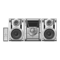
Panasonic SA-AK230GCP Service Manual (105 pages)
CD Stereo System
Brand: Panasonic
|
Category: Stereo System
|
Size: 17.54 MB
Table of Contents
Advertisement
Panasonic SA-AK230GCP Service Manual (105 pages)
CD Stereo system
Brand: Panasonic
|
Category: Stereo System
|
Size: 16.98 MB