Sign In
Upload
Manuals
Brands
Omron Manuals
Controller
SYSMAC SRM1-V2
Omron SYSMAC SRM1-V2 Manuals
Manuals and User Guides for Omron SYSMAC SRM1-V2. We have
2
Omron SYSMAC SRM1-V2 manuals available for free PDF download: Programming Manual, Operation Manual
OMRON SYSMAC SRM1-V2 Programming Manual (615 pages)
Brand:
OMRON
| Category:
Controller
| Size: 3.64 MB
Table of Contents
Table of Contents
6
Precautions
16
General Precautions
17
Intended Audience
17
Safety Precautions
17
Operating Environment Precautions
19
Application Precautions
20
Section 1 PC Setup
23
PC Setup
24
Changing the PC Setup
24
CPM1/CPM1A PC Setup Settings
25
CPM2A/CPM2C PC Setup Settings
29
SRM1(-V2) PC Setup Settings
35
Basic PC Operation and I/O Processes
38
Startup Mode
38
Hold Bit Status
39
Program Memory Write-Protection
39
RS-232C Port Servicing Time (CPM2A/CPM2C/SRM1(-V2) Only)
40
Peripheral Port Servicing Time
40
Cycle Monitor Time
40
Minimum Cycle Time
41
Input Time Constants
41
CPM2C Changes in SW2
43
Error Log Settings
43
Section 2 Special Features
46
Special Features
46
CPM2A/CPM2C Interrupt Functions
47
Processing the same Memory Locations with the Main Program
48
And Interrupt Subroutines
48
Interrupt Inputs
51
Interval Timer Interrupts
58
Precautions on Programming Interrupts
63
CPM2A/CPM2C High-Speed Counters
66
Using High-Speed Counters
68
Input Interrupts in Counter Mode
89
CPM1/CPM1A Interrupt Functions
98
Types of Interrupts
98
Input Interrupts
100
Masking All Interrupts
104
Interval Timer Interrupts
105
High-Speed Counter Interrupts
107
SRM1(-V2) Interrupt Functions
115
Types of Interrupts
115
CPM2A/CPM2C Pulse Output Functions
118
Interval Timer Interrupts
119
CPM2A/CPM2C Pulse Output Functions
119
Using Pulse Outputs with Variable Duty Ratio
132
Using Pulse Outputs with Trapezoidal Acceleration and Deceleration
138
CPM1A Pulse Output Functions
152
Programming Example in Continuous Mode
153
Programming Example in Independent Mode
153
Using Pulse Output Instructions
153
Changing the Frequency
154
Stopping Pulse Output
154
Synchronized Pulse Control (CPM2A/CPM2C Only)
155
Data Computation Standards
167
Pulse Outputs
167
Synchronized Pulse Control
167
Analog I/O Functions (CPM1/CPM1A/CPM2A/CPM2C Only)
168
Temperature Sensor Input Functions (CPM1A/CPM2A/CPM2C Only)
168
Compobus/S I/O Slave Functions (CPM1A/CPM2A/CPM2C Only)
168
Compobus/S I/O Master Functions (SRM1(-V2) and CPM2C-S Only)
169
Analog Controls (CPM1/CPM1A/CPM2A Only)
171
Quick-Response Inputs
174
CPM1/CPM1A Quick-Response Inputs
174
CPM2A/CPM2C Quick-Response Inputs
175
Macro Function
178
Calculating with Signed Binary Data
179
Differential Monitor
180
Definition of Signed Binary Data
180
Arithmetic Flags
180
Inputting Signed Binary Data Using Decimal Values
180
Expansion Instructions (CPM2A/CPM2C/SRM1(-V2) Only)
181
CPM2A/CPM2C/CPM2C-S Expansion Instructions
182
SRM1(-V2) Expansion Instructions
183
Using the CPM2A/CPM2C Clock Function
184
Data Area Words
184
Setting the Time
184
Section 3 Using Expansion Units
185
Section 3
185
Analog I/O Units
186
CPM1A-MAD01 Analog I/O Unit
186
CPM1A-MAD11 and CPM2C-MAD11 Analog I/O Units
197
Temperature Sensor Units
213
CPM1A/CPM2A Temperature Sensor Units
213
CPM2C Temperature Sensor Units
214
Using Temperature Sensor Units
215
Connecting Temperature Sensor Units
215
Ladder Programming
222
Two-Decimal-Place Mode
228
Compobus/S I/O Link Units
234
Devicenet I/O Link Unit
239
Using Expansion Units
185
Section 4 Communications Functions
245
Communications Functions
245
SECTION 4 Communications Functions
245
Introduction
246
Overview
246
Wiring Ports
246
CPM1/CPM1A Communications Functions
247
Host Link Communications
247
One-To-One NT Link Communications
248
One-To-One PC Link Communications
249
CPM2A/CPM2C Communications Functions
251
Host Link Communications
251
No-Protocol Communications
271
One-To-One NT Link Communications
280
One-To-One PC Link Communications
283
SRM1(-V2) Communications Functions
288
Host Link Communications
288
No-Protocol Communications
292
One-To-One NT Link Communications
297
One-To-N NT Link Communications
298
One-To-One PC Link Communications
299
Host Link Commands
301
Ir/Sr Area Read - Rr
301
Lr Area Read - Rl
302
Hr Area Read - Rh
302
Pv Read - Rc
302
Tc Status Read - Rg
303
DM Area Read - Rd
303
Ar Area Read - Rj
304
Ir/Sr Area Write - Wr
305
Lr Area Write - Wl
305
Hr Area Write - Wh
306
Pv Write - Wc
306
Tc Status Write - Wg
307
DM Area Write - Wd
308
Ar Area Write - Wj
308
Sv Read 1 - R
309
Sv Read 2 - R
310
Sv Change 1 - W
311
Sv Change 2 - W
312
Status Read - Ms
313
Status Write - Sc
314
Error Read - Mf
315
Forced Reset - Kr
317
Multiple Forced Set/Reset - Fk
318
Forced Set/Reset Cancel - Kc
319
Pc Model Read - MM
320
Test - Ts
320
Program Read - Rp
321
Program Write - Wp
321
Compound Command - Qq
322
Abort - Xz
324
Initialize
324
Txd Response - Ex
324
Undefined Command - IC
325
Section 5 Memory Areas
326
Memory Areas
326
Memory Area Functions
327
Memory Area Structure
327
SECTION 5 Memory Areas
328
Functions
330
I/O Allocation for CPM1/CPM1A/CPM2A Pcs
332
CPM1/CPM1A/SRM1(-V2) Flash Memory
332
CPU Units
332
Expansion I/O Units
336
Expansion Units
337
Examples of Expansion Unit and Expansion I/O Unit Allocation
338
I/O Allocation for CPM2C Pcs
342
CPU Units
342
Expansion I/O Units
344
Expansion Units
347
Examples of Expansion Unit and Expansion I/O Unit Allocation
348
Ladder-Diagram Programming
351
Basic Procedure
352
Instruction Terminology
352
Basic Ladder Diagrams
353
Controlling Bit Status
372
Work Bits (Internal Relays)
374
Programming Precautions
376
Program Execution
378
Instruction Set
379
SECTION 7 Instruction Set
379
Notation
382
Instruction Format
382
Data Areas, Definer Values, and Flags
382
Differentiated Instructions
384
Coding Right-Hand Instructions
385
Instruction Tables
388
Ladder Diagram Instructions
394
Bit Control Instructions
395
No Operation - Nop
399
End - End
399
INTERLOCK and INTERLOCK CLEAR - IL(02) and ILC(03)
399
JUMP and JUMP END - JMP(04) and JME
401
User Error Instructions: FAILURE ALARM and RESET - FAL(06) and SEVERE FAILURE ALARM - FALS
403
Step Instructions: STEP DEFINE and STEP START-STEP(08)/SNXT
403
STEP DEFINE and STEP START-STEP(08)/SNXT(09)
403
Timer and Counter Instructions
406
Shift Instructions
422
Data Movement Instructions
429
Data Control Instructions
439
Comparison Instructions
450
Conversion Instructions
457
BCD Calculation Instructions
475
Binary Calculation Instructions
485
Special Math Instructions
489
Logic Instructions
497
Increment/Decrement Instructions
501
Subroutine Instructions
502
Pulse Output Instructions
505
Special Instructions
515
Interrupt Control Instructions
519
Communications Instructions
523
Section 8
529
PC Operations and Processing Time
529
CPM1/CPM1A Cycle Time and I/O Response Time
530
The CPM1/CPM1A Cycle
530
CPM1/CPM1A Cycle Time
531
I/O Response Time
532
One-To-One PC Link I/O Response Time
533
Interrupt Processing Time
535
CPM1/CPM1A Instruction Execution Times
536
CPM2A/CPM2C Cycle Time and I/O Response Time
541
CPM2A/CPM2C Cycle Time
541
I/O Response Time
542
One-To-One PC Link I/O Response Time
543
Interrupt Processing Time
545
CPM2A/CPM2C Instruction Execution Times
546
SRM1(-V2) Cycle Time and I/O Response Time
555
The SRM1(-V2) Cycle
555
SRM1(-V2) Cycle Time
556
I/O Response Time
558
One-To-One PC Link I/O Response Time
559
Interrupt Processing Time
560
SRM1(-V2) Instruction Execution Times
561
Troubleshooting
567
Introduction
568
Programming Console Operation Errors
568
Programming Errors
569
User-Defined Errors
570
Operating Errors
571
Error Log
573
Host Link Errors
575
Troubleshooting Flowcharts
575
A Programming Instructions
576
B Error and Arithmetic Flag Operation
581
C Memory Areas
584
D I/O Assignment Sheet
601
E Program Coding Sheet
602
F List of FAL Numbers
605
G Extended ASCII
607
Index
608
Revision History
614
Advertisement
Omron SYSMAC SRM1-V2 Operation Manual (126 pages)
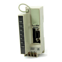
CompoBus/S controller
Brand:
Omron
| Category:
Control Unit
| Size: 0.83 MB
Table of Contents
Table of Contents
4
About this Manual
6
Precautions
7
Intended Audience
8
General Precautions
8
Safety Precautions
8
Operating Environment Precautions
9
Application Precautions
9
Introduction
12
SRM1 Features and Functions
13
System Configuration
14
Basic Configuration
14
Srm1 Models
15
Peripheral Connections
16
Procedures from System Design to Test Operation
18
I/O and Data Area Allocations
19
I/O Allocations
19
Data Area Allocation
20
Section 2 Specifications and Components
21
Specifications and Components
21
Specifications
22
General Specifications
22
Characteristics
23
Compobus/S Communications Specifications
24
Unit Components
25
Section 3 Installation and Wiring
27
Installation and Wiring
27
System Design
28
Power Supply Wiring
28
Interlock and Limit Circuits
28
Power Supply Sequence
28
Selecting an Installation Site
29
Installation Site Conditions
29
Panel/Cabinet Installation
29
Installing the SRM1
30
Surface Installation
30
DIN Track Installation
30
Wiring and Connections
31
General Precautions for Wiring
31
Power Supply Wiring
33
Compobus/S Transmission Line Wiring
33
RS-232C Port Wiring
34
Host Link Connections
36
One-To-One NT Link
40
One-To-N NT Link
40
One-To-One PC Link Connections
41
Basics
41
Restrictions
42
One-To-One PC Link Connections
42
Cable Connections
42
PC Setup Settings
42
Section 4 Using the Programming Console
43
Using the Programming Console
43
Basic Operations
44
Compatible Programming Consoles
44
Basic Operations
45
Connecting the Programming Console
45
Changing the Srm1'S Mode
45
Programming Console Operations
46
Overview
46
Clearing Memory
47
Programming Console Operations
47
Reading/Clearing Error Messages
48
SECTION 5 Test Runs and Error Processing
48
Buzzer Operation
49
Reading um Area Information
50
Setting Expansion Instructions
50
Setting and Reading a Program Memory Address and Monitoring I/O Bit Status
51
Instruction Search
51
Bit Operand Search
52
Inserting and Deleting Instructions
53
Entering or Editing Programs
54
Checking the Program
57
Bit, Digit, Word Monitor
57
Differentiation Monitor
59
Binary Monitor
60
Three-Word Monitor
60
Signed Decimal Monitor
61
Unsigned Decimal Monitor
61
Three-Word Data Modification
62
Changing Timer, Counter SV
62
Hexadecimal, BCD Data Modification
63
Binary Data Modification
64
Signed Decimal Data Modification
65
Unsigned Decimal Data Modification
66
Force Set, Reset
66
Clear Force Set/Reset
67
Hex-ASCII Display Change
67
Displaying the Cycle Time
68
Section 5 Test Runs and Error Processing
69
Test Runs and Error Processing
69
Startup Procedure
70
Flowchart for Configuring and Checking the System
70
SRM1 Test Run Procedure
70
Flash Memory Precautions
71
Entering the Program
72
Before Programming
72
Clearing Memory
72
Ladder Programming Example
74
Writing the Program
78
Test Run
81
Checking the Program
81
Error Processing
82
Non-Fatal Errors
82
Fatal Errors
82
Error Processing
83
Identifying Errors
83
User-Defined Errors
83
Reading/Clearing Error Messages
84
Programming Console Operation Errors
85
Programming Errors
85
Troubleshooting Flowcharts
87
Troubleshooting Flowcharts
88
Section 6 Expansion Memory Unit
93
Expansion Memory Unit
93
Overview
94
Memory Areas
94
Precautions
94
SECTION 6 Expansion Memory Unit
94
Specifications and Nomenclature
95
Specifications
95
Nomenclature
95
Handling
96
Mounting/Removing EEPROM
96
PC Connections
97
Uploading Programs
98
Downloading Programs
99
A Standard Models
102
B External Dimensions
106
Glossary
107
Index
123
Revision History
126
Advertisement
Related Products
Omron SRM-V2
Omron Smart Process Control CJ-Series
Omron SYSMAC CQM1
Omron SCON-CA
Omron SYSMAC CS Series
Omron SYSMAC One NSJ Series
Omron SYSMAC CV Series
Omron SGE-225 4
Omron SGE-245L
Omron SYSMAC NJ Series
Omron Categories
Blood Pressure Monitor
Controller
Accessories
Switch
Inverter
More Omron Manuals
Login
Sign In
OR
Sign in with Facebook
Sign in with Google
Upload manual
Upload from disk
Upload from URL