Sign In
Upload
Manuals
Brands
OMRON Manuals
Processor
Sysmac CP1H
OMRON Sysmac CP1H Manuals
Manuals and User Guides for OMRON Sysmac CP1H. We have
4
OMRON Sysmac CP1H manuals available for free PDF download: Operation Manual, Brochure, Datasheet, Application And Setup Manual
Omron Sysmac CP1H Operation Manual (810 pages)
CPU Unit SYSMAC CP Series
Brand:
Omron
| Category:
Processor
| Size: 13.9 MB
Table of Contents
Table of Contents
11
About this Manual
15
Related Manuals
17
Precautions
23
General Precautions
24
Intended Audience
24
Safety Precautions
24
Operating Environment Precautions
26
Application Precautions
27
Conformance to EC Directives
30
Applicable Directives
30
Concepts
30
Conformance to EC Directives
31
Relay Output Noise Reduction Methods
31
Conditions for Meeting EMC Directives When Using CP-Series Relay Expansion I/O Units
33
Section 1 Features and System Configuration
35
Features and System Configuration
35
Features and Main Functions
36
CP1H Overview
36
Features
40
System Configuration
49
Basic System
49
System Expansion
51
System Expansion with CJ-Series Units
55
Restrictions on System Configuration
57
Connecting Programming Devices
60
Connecting to a USB Port
60
Connecting to a Serial Port
69
Function Charts
71
Cpu Units
72
Function Blocks
74
Overview of Function Blocks
74
Advantages of Function Blocks
74
Section 2 Nomenclature and Specifications
77
Nomenclature and Specifications
77
Part Names and Functions
78
CP1H CPU Units
78
CP1W-CIF01 RS-232C Option Boards
82
CP1W-CIF11/CIF12 RS-422A/485 Option Boards
83
Specifications
84
CP1H CPU Units
84
I/O Memory Details
88
I/O Specifications for XA and X CPU Units
89
Built-In Analog I/O Specifications (XA CPU Units Only)
97
I/O Specifications for y CPU Units
99
CP-Series Expansion I/O Unit I/O Specifications
106
CP1H CPU Unit Operation
110
Overview of CPU Unit Configuration
110
Flash Memory Data Transfers
114
Memory Cassette Data Transfers
116
CPU Unit Operation
118
General Flow
118
I/O Refreshing and Peripheral Servicing
119
I/O Refresh Methods
120
Initialization at Startup
122
CPU Unit Operating Modes
123
Operating Modes
123
Status and Operations in each Operating Mode
123
Operating Mode Changes and I/O Memory
124
Startup Mode Setting
124
Power off Operation
125
Overview
125
Instruction Execution for Power Interruptions
126
Computing the Cycle Time
127
CPU Unit Operation Flowchart
127
Cycle Time Overview
128
Functions Related to the Cycle Time
130
Minimum Cycle Time
130
I/O Refresh Times for PLC Units
131
Cycle Time Calculation Example
133
Online Editing Cycle Time Extension
133
I/O Response Time
134
Interrupt Response Times
135
Serial PLC Link Response Performance
137
Pulse Output Start Time
137
Pulse Output Change Response Time
138
Section 3 Installation and Wiring
139
Installation and Wiring
139
Fail-Safe Circuits
140
Installation Precautions
141
Installation and Wiring Precautions
141
Mounting
143
Mounting in a Panel
143
Connecting CP-Series Expansion Units and Expansion I/O Units
147
Connecting CJ-Series Units
149
DIN Track Installation
150
Wiring CP1H CPU Units
152
Wiring Power Supply and Ground Lines
153
Wiring Built-In I/O
155
Wiring Safety and Noise Controls
159
Wiring Methods
160
Example I/O Wiring for X and XA CPU Units
160
Example I/O Wiring for y CPU Units
162
Pulse Input Connection Examples
163
Pulse Output Connection Examples
164
Wiring Built-In Analog I/O (XA CPU Units Only)
166
CP-Series Expansion I/O Unit Wiring
169
Section 4 I\/O Memory Allocation
177
I/O Memory Allocation
177
Overview of I/O Memory Area
178
I/O Memory Area
178
Overview of the Data Areas
180
Clearing and Holding I/O Memory
184
Hot Start/Hot Stop Functions
184
I/O Area and I/O Allocations
186
Overview
186
Allocations to Built-In General Purpose I/O on the CPU Unit
187
Allocations to CP1H y CPU Units (12 Inputs/8 Outputs)
188
Allocations to CP1W Expansion Units and Expansion I/O Units
188
I/O Allocation Examples
192
Built-In Analog I/O Area (XA CPU Units Only)
193
Data Link Area
194
CPU Bus Unit Area
195
Special I/O Unit Area
196
Serial PLC Link Area
197
Devicenet Area
197
Internal I/O Area
199
Holding Area (H)
199
Auxiliary Area (A)
200
TR (Temporary Relay) Area
200
Timers and Counters
201
Timer Area (T)
201
Counter Area (C)
203
Data Memory Area (D)
204
Changing the BCD or Binary Mode for Counters and Timers
204
Index Registers
206
Using Index Registers
209
Precautions for Using Index Registers
211
Data Registers
213
Task Flags
215
Condition Flags
215
Clock Pulses
217
Section 5 Basic Cp1H Functions
219
Basic CP1H Functions
219
Interrupt Functions
220
Overview of CP1H Interrupt Functions
220
Input Interrupts (Direct Mode)
224
Input Interrupts (Counter Mode)
229
Scheduled Interrupts
232
High-Speed Counter Interrupts
235
High-Speed Counters
244
External Interrupts
244
Overview
244
High-Speed Counter Specifications
245
Procedure
251
PLC Setup
252
High-Speed Counter Terminal Allocation
252
Pulse Input Connection Examples
255
Ladder Program Example
256
Additional Capabilities and Restrictions
259
Pulse Outputs
264
Overview
264
Pulse Output Specifications
266
Pulse Output Terminal Allocations
268
Pulse Output Patterns
274
Origin Search and Origin Return Functions
289
Origin Return
309
Pulse Output Procedures
311
Instructions Used for Pulse Outputs
313
Variable Duty Factor Pulse Outputs (PWM(891) Outputs)
324
Example Pulse Output Applications
325
Quick-Response Inputs
356
Analog I/O (XA CPU Units)
359
Advanced Functions
373
Serial Communications
374
Serial Plc Links
383
Host Link Communications
392
Analog Adjuster and External Analog Setting Input
396
External Analog Setting Input
397
7-Segment LED Display
398
Battery-Free Operation
400
Memory Cassette Functions
402
Mounting and Removing a Memory Cassette
403
Memory Cassette Data Transfer Function
406
Program Protection
410
Write Protection
413
Protecting Program Execution Using the Lot Number
415
Failure Diagnosis Functions
417
Simulating System Errors
419
Output off Bit
420
Clock
421
Using CP-Series Expansion Units and Expansion I/O Units
423
Connecting CP-Series Expansion Units and Expansion I/O Units
424
Analog Input Units
425
Analog Output Units
438
Analog I/O Units
448
Part Names
462
Temperature Sensor Units
478
Wiring Diagram
500
Compobus/S I/O Link Units
512
Operating Procedure
514
LCD Option Board
517
Features
518
Specifications
519
Part Names
520
Installation and Removing
521
Basic Operation
522
Screen Transitions
523
Operation Examples
525
LCD Option Board Function
527
Plc Mode
530
Message Screen
555
Data Backup
566
Language Selection
569
Plc Cycle Time
570
Plc Clock Setting
571
Plc System Information
572
Lcd Backlight Setting
573
Lcd Contrast Setting
574
Lcd Factory Setting
575
Trouble Shooting
576
Deleting Eeprom Error
577
Ethernet Option Board
579
Ethernet Option Board Function Guide
580
Receiving Data from Omron Plcs Using Ethernet
582
Features
583
System Configuration
584
Specifications
585
FINS Communications
586
Overview of Fins Communication Service
587
Part Names
588
Comparison with Previous Models
589
Installation and Initial Setup
591
Network Installation
594
Web Browser Setting Function
596
Memory Allocations
599
DM Area Allocation
601
Mode Setting
602
Subnet Mask
602
Web Browser Setup and Display
605
Unit Information
612
Unit Status
613
Fins Status
614
Error Log
615
Trouble Shooting
616
Error Status
619
Sample Application
620
Buffer Configuration (CP1W-CIF41)
624
Program Transfer, Trial Operation, and Debugging
625
Program Transfer
626
Trial Operation and Debugging
626
Differential Monitoring
627
Tracing Data
630
Troubleshooting
633
Error Classification and Confirmation
634
Troubleshooting
639
Error Processing Flowchart
640
No Operation When Power Is Supplied
640
Fatal Errors
641
Cpu Errors
646
Other Errors
650
Error Log
651
Troubleshooting Unit Errors
652
Inspection and Maintenance
655
Inspections
656
Unit Replacement Precautions
657
Replacing User-Serviceable Parts
658
Appendices
661
Standard Models
661
Dimensions Diagrams
669
Auxiliary Area Allocations by Function
677
Initial Settings
677
Cpu Unit Settings
677
Data Tracing
683
Comment Memory
684
Auxiliary Area Allocations by Address
697
Memory Map
745
Connections to Serial Communications Option Boards
747
Connection Methods
747
Connection Examples
765
PLC Setup
773
Background Execution Settings
774
Input Constant Settings
776
Pulse Output 0 Settings
787
Pulse Output 1 Settings
789
Specifications for External Power Supply Expansion
799
Index
801
Revision History
807
Advertisement
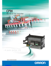
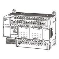
OMRON Sysmac CP1H Brochure (20 pages)
All-in-One Controller
Brand:
OMRON
| Category:
Controller
| Size: 3.3 MB
Table of Contents
Serial Communications
7
Expansion I/O Units
12
Maximum Configuration
15
Specifications
16
Ordering Information
18
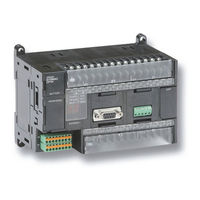
OMRON Sysmac CP1H Datasheet (18 pages)
Brand:
OMRON
| Category:
Controller
| Size: 15.7 MB
Table of Contents
Pulse Output Function
3
High-Speed Counter Function
3
Serial Communications
4
CPU Unit Specifications
10
Warranty
17
Advertisement
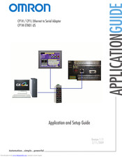
Omron Sysmac CP1H Application And Setup Manual (11 pages)
Ethernet to Serial Adapter
Brand:
Omron
| Category:
Adapter
| Size: 0.58 MB
Table of Contents
Section 1: Introduction
2
Section 2: Applications
3
Section 3: Ethernet to Serial Adapter Setup
4
Section 4: PLC Setup
5
Section 5: Using CX Programmer with the CP1W-ETN01-US
6
Section 6: Using an NS Series HMI with a CP1W-ETN01-US
8
Terms and Conditions of Sale
9
Advertisement
Related Products
OMRON CP1H CPU UNITS - PROGRAMMING 05-2007
Omron SYSMAC CP1H-X40D Series
Omron SYSMAC CP1H-XA40D Series
Omron SYSMAC CP1H-Y20DT-D
OMRON SYSMAC CP1E-N40DR-A
Omron CP1L-EL20DR-D
Omron CP1L-EL20DT-D
Omron CP1L-J14D Series
Omron CP1L-L14D Series
Omron CP1L-EM40DT1-D
OMRON Categories
Blood Pressure Monitor
Controller
Accessories
Switch
Inverter
More OMRON Manuals
Login
Sign In
OR
Sign in with Facebook
Sign in with Google
Upload manual
Upload from disk
Upload from URL