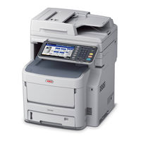
Sign In
Upload
Manuals
Brands
Oki Manuals
Printer
MC760
Oki MC760 Manuals
Manuals and User Guides for Oki MC760. We have
2
Oki MC760 manuals available for free PDF download: Maintenance Manual
Oki MC760 Maintenance Manual (217 pages)
Brand:
Oki
| Category:
Printer
| Size: 21.23 MB
Table of Contents
Set up
46
Maintenance Manual
1
Table of Contents
5
Configuration
7
System Configuration
8
The Configuration of Printer
9
Optional Parts
10
Specifications
11
Copy Function
15
Internet Fax
18
Specification of Interface
19
Connector and Cable of USB Interface
19
General of USB Interface
19
Specification of USB Interface
19
USB Interface Signal
19
Connector and Cable of Network Interface
20
General of Network Interface
20
Signal of Network Interface
20
Specification of Network Interface
20
Outline of Telephone Line Interface
21
Outline of USB Host Interface
21
Telephone Line Interface Connector and Cable
21
Telephone Line Interface Signal
21
Telephone Line Interface Specification
21
USB Host Interface
21
USB Host Interface Connector
21
USB Host Interface Signal
21
Specification of ACC Interface
22
Operating Instructions
23
Electrophotographic Processing Mechanism
24
Printing Process
28
Image Scanning Process
39
Cross-Section View
39
Electrical Configuration
39
Structure and Process of RADF
39
Fundamental Operations
40
Document Detection
43
Document Table Structure
44
Jam Detection
44
Overview
44
Carraige-Assy Drive Mechanism
45
Exposure Block
45
Set up
46
Notes and Precautions
47
Unpack Method
48
Setting Method
49
List of Equipments and Accessories
50
Assembling Method
51
Assemble the Main Body of the MFP
51
Cable Connect
58
Turn the Power off
59
Optional Part Installation and Confirmation
60
Setting Content Print (Configuration)
65
Connecting Method
66
User Used Paper Confirmation
70
Component Replacement
71
Precautions on Component Replacement
72
Maintenance Tool
73
Method of Component Replacement
74
Belt Unit
74
Fuser Unit
75
Right Side Cover
75
Left Side Cover
76
Scanner Unit
76
Faceup Tray
77
Rear Cover
77
CU/PU Pcb/Low Voltage Power Supply
78
LED Assy/ LED Assy Spring
78
Plate-Board-R Assy/Guide-Cable Power Low
80
Stay-R
80
Top Cover Assy
81
Frame Assy Top Front
82
Top Cover
82
Board MFH
83
Hopping Motor/ Fuse Motor
84
Guide Eject Assy/ Color Regist Assy/ Board-IBY
85
Fan(Fuser) / Belt Motor/ High-Voltage Board/ Cover Open Switch
86
Mpt Assy
86
Cover Assy Front/ Board-RSF/MPT Hopping Roller/ Frame Assy Separator Feeder Assy Regist
87
Plate-Driver/ Shaft-Liftup/ Hopping Cover
88
Feed Roller
89
Plate-Assy-Side R/ Plate-Assy-Side L
89
Eject Sensor/Micro-SW
90
Stapler (for Stapler Model Only)
92
Tray-Assy-Document/Cover-ADF-R
93
ADF-Unit
94
Sheet-Document / Paper-Weight-Assy / Spring-PW-ADF
95
Hinge-Assy-L / Hinge-Assy-R
96
Guide-Retard / Roller / Motor / Clutch / Solenoid
97
Guide-Assy-Retard
98
Frame-Assy-FB
99
Oiling Spots
100
Maintenance Menu
111
System Maintenance Menu (for Maintenance Engineer)
112
Maintenance Utility
112
Maintenance Menu Functions
113
Self-Diagnostic Mode
113
Operation Panel
113
Ordinary Self-Diagnostic Mode (Level)
115
Switch Scan Test
116
Motor Clutch Test
118
Test Print
120
Color Registration Correction Test
126
Density Correction Test
127
Consumable Item Counter Display
129
Number of Print Copies Counter Display
130
Switching between the Factory Mode and the Shipping Mode
130
Self-Diagnostic Function Setting
131
LED Head Serial Number Display
132
Functions of Keys at Power on
133
How to Enter the Scanner Maintenance Menu
134
Setups Upon Completion of Part Replacement
136
Precautions When Replacing the Pu Board
136
Density Control Manual Setting
138
Periodic Maintenance
139
Cleaning
140
How to Clean the LED Lens Array
141
How to Clean the Pickup Roller
143
How to Clean the Paper Feed Rollers for MP Tray
144
How to Clean the Rollers in the ADF
145
How to Clean the Document Glass
146
How to Clean Inside of MFP
147
Troubleshooting and Repair Procedure
149
Before Starting the Repair Work
150
Confirmation Items before Taking Corrective Action against Abnormalities
150
Precautions When Taking Corrective Action against Abnormality
150
Error Code List
151
Troubleshooting
151
Printer Error Troubleshooting
154
Scanner Error Troubleshooting
160
7.5.4 Preparation for Troubleshooting
162
Preparation for Troubleshooting
162
LCD Display Error
163
LCD Does Not Display Anything
163
Error Messages Related to Operator Panel Are Displayed
163
Abnormal Operations of Printer after the Power Is Turned on
164
Any Operation Does Not Start at All
164
Abnormal Sound Is Heard
164
Bad Odors Are Generated
165
Rise-Up Time Is Slow
165
Document Jam
172
Paper Feed Jam (Error Code E130: 1St Tray)
173
Jam Occurs Immediately after the Power Is Turned On. (1St Tray)
173
Jam Occurs Immediately after the Paper Feed Is Started. (1St Tray)
173
Feed Jam (Error Code E202)
175
Jam Occurs Immediately after the Power Is Turned on
175
Jam Occurs Immediately after the Paper Feed Is Started
175
Paper Feed Jam (Error Code E120: Multipurpose Tray)
176
Jam Occurs Immediately after the Power Is Turned on
176
(Multipurpose Tray)
176
Jam Occurs Immediately after Paper Feed Is Started
177
(Multipurpose Tray)
177
Paper Running Jam (Error Code E010)
178
Jam Occurs Immediately after the Power Is Turned on
178
Jam Occurs Immediately after a Paper Is Taken into Printer
178
Jam Occurs in the Middle of Paper Running Path
179
Jam Occurs Immediately after Paper Has Reached the Fuser
180
Paper Unloading Jam (Error Code E020)
180
Paper Unloading Jam Occurs Immediately after the Power Is Turned on
180
Paper Unloading Jam Occurs after a Paper Is Taken into Printer
181
Paper Unloading Jam Occurs in the Middle of Paper Running Path
182
Two-Sided Printing Jam (Error Code: E580, E520, E110, E510, E570)
182
Two-Sided Printing Jam Occurs Immediately after the Power Is Turned on
182
Two-Sided Printing Jam Occurs During Taking in the Paper into Duplex Unit
183
Two-Sided Printing Jam Occurs in the Process of Reversing Paper
183
Two-Sided Printing Jam Occurs During Transporting Paper Inside the Duplex Unit
184
Paper Is Not Supplied from the Duplex Unit to the Regist Roller
184
Paper Size Error (Error Code E061, E062, E063, E064, E065)
184
Jam Occurs When Paper End Is Located Near the IN1 Sensor
184
ID Unit Up/Down Error (Service Call CE7A)
185
Error Occurs During the up Movement of the ID Unit
185
Error Occurs During the down Movement of the ID Unit
185
Fuser Unit Error (Error C41A,C41B,C449,C446,C41C,C41D,C468,C466)
186
Error Occurs Immediately after the Power Is Turned on
186
Error Occurs Approx. 1 Minute after the Power Is Turned on
186
Motor Fan Error (Error Code C0A2, C0A1, C0A5, C0A6)
187
The Low Voltage Power Supply Fan Does Not Rotate Immediately after the Power Is Turned on
187
Duplex Fan Does Not Rotate During the Duplex Printing
187
All Fans of the Printer Do Not Rotate
187
Option Unit Cannot be Recognized
188
Duplex Unit Cannot be Recognized
188
Option Try Unit Cannot be Recognized
188
Print Speed Is Slow. (Performance Is Low.)
188
Print Speed Decreases
188
LED Head Cannot be Recognized. (Error Code CE82, CE83, CE84, CE85)
189
Service Call CE82 to CE85 (LED HEAD Missing)
189
Toner Cartridge Cannot be Recognized. (Error Code C3B3,C3A3,C393,C383)
190
Error Caused by the Consumable Items
190
Error Caused by the Toner Sensor
190
Error Caused by the Defective Mechanism
191
Fuse Cut Error (Error Codes C3EA,C3EB,C3EC,C3ED,,C3E2,C4C0)
191
Fuse Cut Error
191
Humidity Sensor Error (Error Code CE51)
192
Humidity Sensor Error
192
Wiring Diagram
193
7.5.5 Troubleshooting the Abnormal Images
194
Troubleshooting the Abnormal Images
194
Color Are Faded-Out and Blurred
195
Color Has Faded-Out and Blurred Entirely. (Refer to Figure 7-2A.)
195
Stain on White Print (Overall Stain)
196
Stain on White Print (Partial Stain)
196
Stain on White Print (Refer to Figure 7-2B.)
196
White Print (Refer to Figure 7-2C.)
197
White Print over Entire Page
197
Black Banding/Black Streaking in Vertical Direction
198
Cyclic Abnormality (Refer to Figure 7-2E.)
198
Cyclic Abnormality Occurs in Vertical Direction
198
Thin Vertical Line (with Color) (Refer to Figure 7-2D.)
198
Thin Vertical Line (Without Color) (Refer to Figure 7-2F.)
198
Entirely Black Print
199
All Black Print over Entire Page
199
Fuse Check
201
Paper Cassette Switches Versus Paper Size Correspondence Table
202
Connection Diagrams
203
Resistance Value Check
204
Parts Location
208
Heavy Color Registration Error
199
Display of the Message "Color Adjustment Is in Progress" Appears Only Short Time
199
Though REG ADJUST TEST of Engine Maintenance Function Is Ok, Color Blur Occurs
199
Advertisement
Oki MC760 Maintenance Manual (223 pages)
Brand:
Oki
| Category:
All in One Printer
| Size: 28.03 MB
Table of Contents
Periodic Maintenance
138
Table of Contents
4
Configuration
6
System Configuration
7
The Configuration of Printer
8
Optional Parts
9
Specifications
10
Specification of Interface
18
Specification of USB Interface
18
General of USB Interface
18
Connector and Cable of USB Interface
18
USB Interface Signal
18
Specification of Network Interface
19
General of Network Interface
19
Connector and Cable of Network Interface
19
Signal of Network Interface
19
USB Host Interface
20
USB Host Interface Signal
20
Outline of USB Host Interface
20
USB Host Interface Connector
20
Telephone Line Interface Signal
20
Telephone Line Interface Connector and Cable
20
Outline of Telephone Line Interface
20
Telephone Line Interface Specification
20
Specification of ACC Interface
21
Operating Instructions
22
Electrophotographic Processing Mechanism
23
Printing Process
27
Electrical Configuration
38
Cross-Section View
38
Structure and Process of RADF
38
Image Scanning Process
38
Fundamental Operations
39
Document Detection
42
Overview
43
Jam Detection
43
Document Table Structure
43
Exposure Block
44
Carraige-Assy Drive Mechanism
44
Set up
45
Notes and Precautions
46
Unpack Method
47
Setting Method
48
List of Equipments and Accessories
49
Assembling Method
50
Assemble the Main Body of the MFP
50
Cable Connect
57
Optional Part Installation and Confirmation
59
Setting Content Print (Configuration)
64
Connecting Method
65
User Used Paper Confirmation
69
Component Replacement
70
Precautions on Component Replacement
71
Method of Component Replacement
73
Belt Unit
73
Fuser Unit
74
Right Side Cover
74
Left Side Cover
75
Scanner Unit
75
Faceup Tray
76
Rear Cover
76
CU/PU Pcb/Low Voltage Power Supply
77
LED Assy/ LED Assy Spring
77
Stay-R
79
Plate-Board-R Assy/Guide-Cable Power Low
79
Top Cover Assy
80
Top Cover
81
Frame Assy Top Front
81
Board MFH
82
Hopping Motor/ Fuse Motor
83
Cleaning
139
How to Clean the LED Lens Array
140
How to Clean the Pickup Roller
142
How to Clean the Paper Feed Rollers for MP Tray
143
How to Clean the Rollers in the ADF
144
How to Clean the Document Rollers in the ADF
145
How to Clean the Document Glass
146
How to Clean Inside of MFP
147
Preparation for Troubleshooting
162
Error Messages Related to Operator Panel Are Displayed
163
LCD Display Error
163
LCD Does Not Display Anything
163
Abnormal Operations of Printer after the Power Is Turned on
164
Abnormal Sound Is Heard
164
Any Operation Does Not Start at All
164
Bad Odors Are Generated
165
Rise-Up Time Is Slow
165
Jam Occurs Immediately after the Paper Feed Is Started. (1St Tray)
176
Jam Occurs Immediately after the Power Is Turned On. (1St Tray)
176
Paper Feed Jam (Error Code E130: 1St Tray)
176
Feed Jam (Error Code E202)
178
Jam Occurs Immediately after the Paper Feed Is Started
178
Jam Occurs Immediately after the Power Is Turned on
178
Jam Occurs Immediately after the Power Is Turned on
179
Multipurpose Tray
179
Paper Feed Jam (Error Code E120: Multipurpose Tray)
179
Jam Occurs Immediately after Paper Feed Is Started
180
Multipurpose Tray
180
Jam Occurs Immediately after a Paper Is Taken into Printer
181
Jam Occurs Immediately after the Power Is Turned on
181
Paper Running Jam (Error Code E010)
181
Paper Unloading Jam Occurs Immediately after the Power Is Turned on
181
Jam Occurs in the Middle of Paper Running Path
182
Jam Occurs Immediately after Paper Has Reached the Fuser
183
Paper Unloading Jam (Error Code E020)
183
Paper Unloading Jam Occurs after a Paper Is Taken into Printer
184
Paper Unloading Jam Occurs in the Middle of Paper Running Path
185
Two-Sided Printing Jam (Error Code: E580, E520, E110, E510, E570)
185
Two-Sided Printing Jam Occurs Immediately after the Power Is Turned on
185
Two-Sided Printing Jam Occurs During Taking in the Paper into Duplex Unit
186
Two-Sided Printing Jam Occurs in the Process of Reversing Paper
186
Jam Occurs When Paper End Is Located Near the IN1 Sensor
187
Paper Is Not Supplied from the Duplex Unit to the Regist Roller
187
Paper Size Error (Error Code E061, E062, E063, E064, E065)
187
Two-Sided Printing Jam Occurs During Transporting Paper Inside the Duplex Unit
187
Error Occurs During the down Movement of the ID Unit
188
Error Occurs During the up Movement of the ID Unit
188
ID Unit Up/Down Error (Service Call CE7A)
188
Error Occurs Approx. 1 Minute after the Power Is Turned on
189
Error Occurs Immediately after the Power Is Turned on
189
Fuser Unit Error (Error C41A,C41B,C449,C446,C41C,C41D,C468,C466)
189
All Fans of the Printer Do Not Rotate
190
Duplex Fan Does Not Rotate During the Duplex Printing
190
Motor Fan Error (Error Code C0A2, C0A1, C0A5, C0A6)
190
The Low Voltage Power Supply Fan Does Not Rotate Immediately after the Power Is Turned on
190
Duplex Unit Cannot be Recognized
191
Option Try Unit Cannot be Recognized
191
Option Unit Cannot be Recognized
191
Print Speed Decreases
191
Print Speed Is Slow. (Performance Is Low.)
191
LCF Unit Cannot be Recognized
192
LED Head Cannot be Recognized. (Error Code CE82, CE83, CE84, CE85)
193
Service Call CE82 to CE85 (LED HEAD Missing)
193
Error Caused by the Consumable Items
194
Error Caused by the Toner Sensor
194
Toner Cartridge Cannot be Recognized. (Error Code C3B3,C3A3,C393,C383)
194
Error Caused by the Defective Mechanism
195
Fuse Cut Error
195
Fuse Cut Error (Error Codes C3EA,C3EB,C3EC,C3ED,,C3E2,C4C0)
195
Humidity Sensor Error
196
Humidity Sensor Error (Error Code CE51)
196
Jam Occurs Immediately after the Power Is Turned on
196
LCF Paper Feed Jam (Error Code E190)
196
Jam Occurs Immediately after the Paper Feed Is Started
197
Wiring Diagram
198
Troubleshooting the Abnormal Images
199
Color Are Faded-Out and Blurred
200
Color Has Faded-Out and Blurred Entirely. (Refer to Figure 7-2A.)
200
Stain on White Print (Overall Stain)
201
Stain on White Print (Partial Stain)
201
Stain on White Print (Refer to Figure 7-2B.)
201
White Print (Refer to Figure 7-2C.)
202
White Print over Entire Page
202
Black Banding/Black Streaking in Vertical Direction
203
Cyclic Abnormality (Refer to Figure 7-2E.)
203
Cyclic Abnormality Occurs in Vertical Direction
203
Thin Vertical Line (with Color) (Refer to Figure 7-2D.)
203
Thin Vertical Line (Without Color) (Refer to Figure 7-2F.)
203
Display of the Message "Color Adjustment Is in Progress" Appears Only Short Time
204
Heavy Color Registration Error
204
Though REG ADJUST TEST of Engine Maintenance Function Is Ok, Color Blur Occurs
204
Though REG ADJUST Testof Engine Maintenance Function Is NG
204
All Black Print over Entire Page
205
Entirely Black Print
205
Advertisement
Related Products
Oki ML420n
Oki ML320 Turbo
Oki ML395
Oki ML590
Oki ML 520/1
Oki MPS610c
Oki MPS730b
Oki MPS930b
Oki MPS9650c
Oki ML320T/n
Oki Categories
Printer
All in One Printer
Printer Accessories
Fax Machine
Label Maker
More Oki Manuals
Login
Sign In
OR
Sign in with Facebook
Sign in with Google
Upload manual
Upload from disk
Upload from URL