Sign In
Upload
Manuals
Brands
Mercury Manuals
Engine
D4.2L D-Tronic
Mercury D4.2L D-Tronic Manuals
Manuals and User Guides for Mercury D4.2L D-Tronic. We have
2
Mercury D4.2L D-Tronic manuals available for free PDF download: Service Manual, Manual
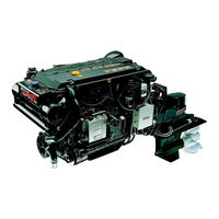
Mercury D4.2L D-Tronic Service Manual (878 pages)
Marine engines in-line Diesel
Brand:
Mercury
| Category:
Engine
| Size: 12.99 MB
Table of Contents
Fuel System
15
Marine Engines
1
Replacement Parts
5
Section 5A - Description
13
Fuel System
14
Section 5E - Edi Diagnosis
15
Section 6A - Seawater Cooling System
16
Section 6B - Closed Cooling System
16
Important Information 1
21
Table of Contents
21
Section 1A - General Information
21
How to Use this Manual
23
Introduction
23
Page Numbering
23
Engine Serial Number / Decal Locations
24
Operation / Duty Cycle
25
Engine Break-In
26
Initial Break-In Procedure
26
Mercury/Quicksilver Lubricants, Sealants and Adhesives
27
Important Information 1
31
Lubricants / Sealants / Adhesives
33
Special Tools
33
Tools
33
Torque Specifications
33
Engine Specifications
34
Sterndrive (MCM) Engines
34
Inboard (MIE) Engines
35
Capacities
36
Engines
36
Drives
36
Transmissions
36
Maintenance Schedules
37
Maintenance Intervals
37
Sterndrive (MCM) Engines
38
Inboard (MIE) Engines
41
Engine External Views
43
Starboard Side View
43
Front View
44
Port Side View
45
Rear View
46
Engine Oil
47
Oil Level
47
Changing Engine Oil and Oil Filter
49
Fuel
51
Precautions
51
General Information
52
Diesel Fuel in Cold Weather
52
Fuel Filter
53
Closed Cooling System
58
Coolant Requirement
58
Checking Level
59
Draining
60
Filling
62
Sacrificial Anodes
63
Removal
63
Inspection
63
Disassembly
64
Reassembly
64
Installation
64
Flushing Seawater System
65
Sterndrive (MCM) Models
65
Inboard (MIE) Models
66
Inspect Water Pickups
68
Sterndrive Gear Housing
68
Inboard Though the Hull Pickup
68
Lubrication
69
Throttle Cable
69
Shift Cable
69
Engine Coupler / U-Joint Shaft Splines 1B-40
70
U-Joints
71
Drive Shaft Extension Models
72
Sterndrive Unit and Transom Assembly
72
Continuity Circuit
73
Continuity Circuit (Continued)
74
Electrical System
75
Engine Mounts
75
Mercathode
75
Power Steering
76
Checking Fluid Level
76
Filling and Bleeding
78
Transmission
79
Checking Fluid Level
79
Power Trim
80
Checking Fluid Level
80
Filling
81
Gear Lube Monitor
82
Checking Fluid Level
82
Filling
82
Seawater Strainer
83
Air Filter
84
Removal
84
Inspection
84
Cleaning
85
Installation
85
Drive Belts
86
General Information
86
Inspection
87
Engine Water Circulating Pump Belt
87
Alternator Belt
88
Power Steering Pump Belt
90
Vacuum Pump Belt
92
Battery
94
Charging System
94
Corrosion and Corrosion Protection
94
Saltwater Operation
94
Freezing Temperature and Cold Weather Operation
95
Cold Weather or Extended Storage
96
Power Package Layup
96
Draining
97
Recommissioning
103
Important Information 1
107
Precautions
109
Poor Boat Performance And/Or Poor Maneuverability
111
Improper Full Throttle Engine RPM
112
RPM too High
112
RPM too Low
112
Engine Cranks over but will Not Start or Starts Hard
113
Electrical
113
Fuel System
113
Miscellaneous
115
Engine will Not Crank over or Starter Inoperative
115
Glow Plugs Inoperative
116
Charging System Inoperative
117
Noisy Alternator
117
Engine Operates Poorly at Idle
118
Engine Operates Poorly at High Rpm
119
Poor Fuel Economy
120
Engine Smoking
121
Black Smoke
121
Blue Smoke
122
White Smoke
122
Exhaust Gas Temperature
123
High
123
Low
123
Turbocharger
124
Engine Noise
125
Valve Cover Area
126
Cylinder Area
126
Camshaft Area
127
Crankshaft Area
128
Miscellaneous
129
Oil Pressure
129
Low Oil Pressure
131
High Oil Pressure
131
Excessive Oil Consumption
132
Water / Coolant in Engine
133
Important Information
133
Water / Coolant in Crankcase Oil
133
Water / Coolant on Top Pistons
134
Engine Overheats
135
Cooling System
135
Mechanical
136
Power Steering
137
Poor, Erratic or no Assist
137
Noisy Pump
138
Fluid Leaks
138
Insufficient Water Flow from Belt Driven Seawater Pump
139
ZF / Hurth Hydraulic Transmission
140
Removal and Installation 2
147
Special Tools
149
Torque Specifications
149
Lubricants / Sealants / Adhesives
150
Removal
150
Installation
153
Engine Installation / Alignment
153
Engine Connections
161
Throttle Cable Installation and Adjustment
167
Shift Cable Installation and Adjustment
169
Troubleshooting Shift Problems
174
Battery Cables
176
Removal and Installation 2
179
Torque Specifications
181
Removal
182
Engine Removal
182
Installation
185
Engine Installation and Initial Alignment
185
Engine Final Alignment
189
Engine Connections
196
Battery Cables
199
Shift Cable Installation and Adjustment
199
Throttle Cable Installation and Adjustment
199
Engine
201
Identification
203
Torque Specifications
204
Tools
206
Special Tools
206
Special Tools (Continued)
207
Snap-On Tools
208
Lubricants/Sealants/Adhesives
209
Engine Specifications
210
Piston Rings
210
Cylinder Liner Diameter
210
Cylinder Liner Protrusion
211
Head Gaskets
211
Cylinder Head
211
Oil Pump
212
Camshaft
212
Valve Lifter
212
Rocker Arm
213
Valve Adjustment
213
Valve
213
Valve Seat
213
Valve Guide
214
Valve Spring
214
Crankshaft
215
Crankshaft (Continued)
216
Connecting Rods
217
Connecting Rod Crank Pin Bore
217
Connecting Rod Bushings
217
Pistons
217
Flywheel
217
Precautions
218
General Information
219
Engine Rotation
219
Engine Firing Order
219
Late Model Cylinder Head Gasket
220
Early Model Cylinder Head Gasket
225
Lubrication System - All Models
228
Examples of Bearing Failures
229
Compression Testing Procedure
230
Engine Cover
231
Removal
231
Cleaning
231
Inspection
231
Installation
231
Valve Covers
232
Removal
232
Cleaning
233
Inspection
233
Installation
234
Water Manifold
237
Exploded Views
237
Removal
238
Cleaning
238
Inspection
238
Installation
239
Cylinder Heads
240
Exploded Views
240
Removal
242
Disassembly
244
Cleaning
244
Inspection
245
Repair
250
Expansion Plugs
250
Assembly
252
Installation - Using Early Model Gaskets
255
Installation - Using Late Model Gaskets
262
Rocker Arm
271
Removal
271
Cleaning
271
Inspection
271
Assembly
272
Installation
273
Timing Gear Cover
277
Exploded View
277
Removal
278
Cleaning
278
Inspection
278
Installation
279
Oil Pump
281
Removal
281
Cleaning
281
Inspection
282
Reassembly
283
Installation
283
Oil Pressure Relief Valve
284
Removal
284
Disassembly
285
Cleaning
285
Inspection
286
Assembly
286
Installation
287
Oil Pan and Oil Pick-Up Tube Assembly
288
Removal
288
Cleaning
289
Inspection
289
Installation
289
Adapter / Oil Thermostat
291
Removal
291
Disassembly
292
Cleaning and Inspection
292
Testing
292
Installation
293
Camshaft
295
Exploded View
295
Testing - Measuring Lobe Lift
296
Removal
296
Inspection
298
Installation
299
Camshaft Bearings
300
Inspection
300
Removal
300
Installation
301
Valve Lifters
302
Removal
302
Cleaning
303
Inspection
303
Installation
304
Valve Push Rods
305
Removal
305
Cleaning
305
Inspection
305
Installation
305
Connecting Rod / Piston Assembly
306
Measuring Rod Bearing Clearance
306
Removal
307
Disassembly
308
Cleaning
309
Inspection
309
Assembly
313
Installation
314
Rear Oil Seal
316
Removal
316
Installation
317
Crankshaft and Main Bearings
318
Removal
318
Cleaning
323
Inspection
324
Installation
327
Cylinder Liners
336
Removal
336
Identification
337
Cleaning and Inspection
338
Installation
339
Flywheel Housing, Coupler / Drive Plate and Flywheel
344
Exploded View
344
Flywheel Housing
348
Sterndrive (MCM) Coupler / Inboard (MIE) Drive Plate
350
Flywheel
351
Engine Mounts
352
Front Mounts
352
MIE (Inboard) Transmission Mounts
353
After Break-In Period
354
Engine 20-Hour Break-In Period
354
Electrical System
357
Identification
359
Lubricants / Sealants / Adhesives
359
Specifications
359
Torque Specifications
359
Replacement Parts
360
Starting System Components
360
Inspection
362
Periodic Inspection
362
Testing Voltage
362
Removal
363
Starter Motor
363
Installation
365
Solenoid Switch
365
Starter Motor
366
Electrical Systems
369
Identification
371
Replacement Parts Warning
371
Specifications
372
Lubricants/Sealers/Adhesives
373
Special Tools
373
Wire Color Code Abbreviations
373
Precautions
374
General
374
Electronic Diesel Injection (EDI) Electrical System Precautions
374
Battery Precautions - Multiple EDI Engines
375
Charging System Components
376
Inspection
377
Circuitry Test
378
Output Circuit
379
Excitation Circuit
380
Sensing Circuit
381
Current Output Test
382
Exploded View
384
Troubleshooting Tests (Alternator on Engine)
378
Removal
385
Alternator
385
Alternator Bracket
385
Installation
386
Alternator Bracket
386
Alternator
386
Battery Isolators
387
Dual Battery Charging Systems
387
Battery Isolator Diagram
388
Electrical Systems
391
Identification
393
Specifications
393
Description
394
Lubricants / Sealants / Adhesives
394
Precautions
394
Special Tools
394
Torque Specifications
394
Glow Plug Testing (Prior to Removal)
395
Removal
396
Cleaning
397
Inspection
397
Installation
398
Glow Plug Actuator Relay and Auxiliary Relay
399
Testing
399
Removal
400
Cleaning
400
Inspection
400
Installation
400
Glow Plug Circuit Diagram
401
Electrical Systems
403
Identification
405
Gauges
405
Panels
405
Lubricants / Sealants / Adhesives
406
Special Tools
406
Tools
406
Wire Color Abbreviations
406
Precautions
407
General Information
408
Special Information
408
Tachometer
408
QSI Series Gauge Lighting Options
409
Gauges
410
Removal
410
Testing
410
Installation
413
Senders
413
Oil Pressure
413
Water Temperature - Primary Station
415
Primary Station Switches
417
Ignition Key Switch
417
Audio Warning Test and Panel Light Switch
419
Audio Warning System
421
Alarm
421
Oil Pressure Switch
422
Water Temperature Switch / Sender
423
Transmission Fluid Temperature Switch
426
Second Station Extension Harness
428
Remote Control / Neutral Start Safety Circuit
431
Primary Station
431
Secondary Station
432
Electrical Systems
435
General Information
437
Lubricants / Sealants / Adhesives
437
Tools
437
Wire Color Abbreviations
437
Sterndrive (MCM) Models
438
Engine Wiring - Starting and Charging System - Page 1 of 4
438
ECM and Fuel System Wiring - Page 1 of 2
442
Wiring Diagrams
442
Quicksilver Instrumentation Wiring - Page 1 of 4
444
Power Trim System Wiring Diagram
448
Mercathode System Wiring Diagram
449
Engine Wiring - Starting and Charging System - Page 1 of 4
450
Inboard (MIE) Models
450
ECM and Fuel System Wiring - Page 1 of 2
454
Quicksilver Primary Instrumentation Wiring - Page 1 of 4
456
Connector
459
Fuel System
467
Introduction
469
Precautions
470
Testing Procedure
471
General Information
472
Basic Knowledge and Tools Required
472
Visual/Physical Inspection
472
Electrostatic Discharge Damage
472
Diagnostic Information
473
Terminology
473
Electronic Control Module (ECM) and Sensors
475
General Description
475
Computers and Voltage Signals
475
Analog Signals
475
Analog Value Conditioning
477
Digital Signals
479
Engine Control Module (ECM)
481
Speed Density System
483
ECM Input and Sensor Descriptions
484
Fuel Management
492
Control
492
Modes of Operation
493
Diagnosis and Testing
496
ECM Reactions During Operation
496
ECM Self-Diagnostics
496
Fuel Systems
501
Identification
503
Lubricants / Sealants / Adhesives
503
Specifications
503
Tools
503
Torque
503
Precautions
504
Exploded View
506
Fuel Delivery Pump, Fuel Filter and Related Components
506
Testing
508
Removal
510
Installation
511
Water Separating Fuel Filter
513
Removal
513
Installation
513
Water Drain Valve Operation
515
Purging Air from the Fuel System
516
Fuel System
519
Identification
521
Specifications
521
Torque
521
Precautions
523
Description
524
Fuel Injector (Cutaway View)
525
Exploded View
526
Injector Test (Engine Misfiring)
527
Removal
528
Inspection
530
Testing
530
Installation
531
Purging Air from Fuel Injectors (Bleeding)
534
Fuel System
537
Identification
538
Pump Code and Identification Number Location
538
Specifications
538
Injection Pump
538
Timing
539
Special Tools
539
Torque Specifications
539
Precautions
541
Description
542
Diesel Fuel in Cold Weather
543
Fuel Ratings
543
Repair and Service
544
General Information
544
Service Information
544
Testing Information
545
Exploded View
546
Fuel Injection Pump Removal
547
Fuel Injection Pump Installation
552
Installation with Engine Assembled
552
Installation During Engine Reassembly
555
Fuel Injection Pump Timing
559
Checking
559
Setting
559
Starting Engine - after Fuel Injection Pump Installation and Timing
564
Fuel Systems
569
General Information
570
Introduction
570
Basic Knowledge and Tools Required
570
Visual/Physical Inspection
571
Electrostatic Discharge Damage
571
Special Tools
572
Special EDI Tools
572
Kent-Moore Tools
572
Service Precautions
573
Diagnostic Information
575
Abbreviations
575
ECM Self-Diagnosis
576
Malfunction Indicator Lamp
577
Intermittent Problems and Malfunction Indicator Lamp
578
Reading Codes
578
Clearing Codes
581
Diagnosis of Driveability Concerns
582
ECM Input and Sensor Diagram
583
ECM Connector Pin Layout
584
Connector Chart
585
Map (Manifold Air Pressure) Sensor
588
ECT (Engine Coolant Temperature) Sensor
590
Fuel Temperature Sensor
592
RPM (Engine Speed) Sensor
594
BARO (Atmospheric Pressure) Sensor
596
Iat (Intake Air Temperature) Sensor
598
Fuel Quantity Actuator (Pump Actuator)
602
Fuel Quantity Sensor (Control Sleeve Position Sensor)
604
Timing Fault
606
TP (Throttle Position) Sensor / Low Idle Switch
608
Battery Voltage
610
Battery (Switched K15)
611
Microcontroller Fault
612
ECM Reference Voltage (U_Ref - 2.5V)
613
Main Relay
614
Timing Actuator (Timing Solenoid Valve)
616
Glow Plug Main Relay (Glow Plug Relay Actuator), if Equipped
618
MIL [Malfunction Indicator Lamp (Diagnostic Lamp)]
626
Fuel Shut off Valve [EAB (Electrical Shut Off)]
630
EEPROM Fault (EEPROM and Configuration)
632
RPM Signal from Injector
636
Troubleshooting for EDI Systems
636
Trouble Codes
636
Display Terminology
637
Troubleshooting Charts
642
Repair Procedures
661
Service Precautions
661
Replacement Parts Warning
662
Lubricants / Sealants / Adhesives
663
Torque Specifications
663
System Components
664
Fuel Injection Pump Repair
666
Wiring Harness Service
667
Relay, Module and Sensor Servicing (On-Board Service)
670
Main Relay
670
ECM (Electronic Control Module)
672
ECT (Engine Coolant Temperature) Sensor
674
Throttle Position (TP) Sensor
678
Engine RPM Speed Sensor
680
Instrumented Injector
680
Idle Speed Setting Circuit
681
Cooling System
683
Lubricants / Sealants / Adhesives
685
Torque Specifications
685
Seawater (Raw Water) System Specifications
686
Seawater Pump Delivery Rates
686
Seawater Pickup Connections
686
Seawater Pickup Connection
687
Seawater Strainer
688
Exploded View - Seawater Pumps
689
D2.8L D-Tronic
689
D4.2L D-Tronic
690
Seawater Flow Diagram
692
Seawater Pump
694
Exploded View
709
General Information
713
Oil / Power Steering / Transmission Fluid Coolers
713
Exploded View
714
Location of Coolers
715
Cleaning Without Removal
716
Inspection before Removal
716
Engine Oil Cooler
717
Power Steering
722
Transmission Fluid Cooler
724
Cooling Systems
729
Specifications
732
Pressure Cap
732
Diagrams and Exploded Views
734
Coolant Flow Diagram
734
Heat Exchanger / Coolant Tank and Related Components
736
Engine Water Circulating Pump
738
Checking Coolant Level
739
Testing Closed Cooling System
740
Testing Coolant for Alkalinity
740
Pressure Testing System
740
Testing for Cylinder Head Gasket Leak
742
Testing Pressure Cap
743
Coolant Change Interval
745
Coolant Requirement
745
Draining Closed Cooling System
745
Cleaning Closed Cooling System
747
Using a Cleaner
747
Flushing the Closed Cooling System
748
Filling the Closed Cooling System
749
Heat Exchanger
754
Cleaning and Inspection
756
Cleaning and Inspection
759
Water Circulating Pump
759
Auxiliary Hot Water Heater Connections
761
Coolant Manifold
761
Corrosion Protection
761
Exploded Views
766
Intake and Exhaust System
785
Exploded Views
788
Typical Intake / Exhaust Manifold
788
Inboard (MIE) Exhaust Systems
790
Representative View of Complete Inboard Exhaust System
791
Locating and Installing the Sterndrive (MCM) Exhaust System
792
Locating and Installing the Inboard (MIE) Exhaust System
793
Exhaust Pipe - Sterndrive (MCM)
795
Intake / Exhaust Manifold
797
Cleaning and Inspection
798
Turbocharger Specifications
805
Turbocharger
805
Exploded Views
808
Turbocharger and Related
809
Turbocharger
809
Testing Turbocharger Boost Pressure 7C-9
811
Checking Turbine Bearings (Assembled)
812
Inspection
830
Exhaust Pipe
830
Drives
839
Specifications
842
Operating Specifications
842
Ratios and Part Numbers
842
Fluid Specifications
842
Lubricants / Sealants / Adhesives
843
Important Information
844
Transmission / Propeller Rotation
845
Transmission Removal
850
Transmission Installation
851
Shift Control and Cables
853
Transmission Shift Lever and Shift Cable Bracket
853
Shift Cable Installation and Adjustment
854
Pressure and Temperature Tests
859
Transmission Repair
859
Torque Specifications
870
Lubricants / Sealants / Adhesives
870
Exploded Views
871
Power Steering Pump
871
Related Components
872
Power Steering Pump
873
Checking Fluid Level
876
Filling and Bleeding
876
Advertisement
Mercury D4.2L D-Tronic Manual (128 pages)
Brand:
Mercury
| Category:
Engine
| Size: 1.6 MB
Table of Contents
Page Warranty Message
1
Welcome
2
Identification Record
3
Table of Contents
4
Warranty Information
6
Owner Warranty Registration
6
International Owner Registration
7
Mercruiser Diesel Limited Warranty
8
Warranty Coverage and Exclusion
10
Transferable Warranty
11
Read this Manual Thoroughly
13
General Information
14
Lanyard Stop Switch
14
Exhaust Emissions
17
Wave and Wake Jumping
18
Impact with Underwater Hazards
19
Safe Boating Suggestions
20
Protecting People in the Water
21
High-Speed and High-Performance Boat Operation
21
Conditions Affecting Operation
22
Weight Distribution
22
Bottom of Boat
22
Cavitation
22
Ventilation
22
Propeller Selection
23
How Elevation and Climate Affect Performance
24
Important Information
25
Operation and Maintenance
25
Freezing Temperature and Cold Weather Operation
27
Drain Plug and Bilge Pump
27
Drive Unit Impact Protection
27
Launching and Boat Operation Care
28
Attention Required after Submersion
28
Trailering Boat
28
Stolen Power Package
28
Replacement Service Parts
28
Do-It-Yourself Maintenance Suggestions
29
Diagnosing EDI Problems (if so Equipped)
30
Multiple EDI Engine Battery Precautions
30
Engine Break-In
31
Sterndrive Unit 10-Hour Break-In Period
32
After Break-In Period
32
End of First Season Checkup
32
100 Hour Checkup
32
Operation
35
Quicksilver Instruments and Instrumentation
35
Electrical System Overload Protection
37
Mercathode System
37
Remote Controls
39
Power Trim
43
Starting, Shifting and Stopping - D3.6L, D4.2L and D4.2L LD
49
Operation Chart - D3.6L, D4.2L and D4.2L LD
52
Starting, Shifting and Stopping - D2.8L D-Tronic and D4.2L D-Tronic
53
Operation Chart - D2.8L D-Tronic and D4.2L D-Tronic
56
Specifications
57
Seacock
57
Seawater Strainer
57
Anti-Freeze/Coolant
57
Fuel Requirements
58
Diesel Fuel in Cold Weather
59
Crankcase Oil
59
Engine Specifications
60
Fluid Capacities
63
Maintenance
64
General Information
64
Maintenance Aids
64
Maintenance Schedules
65
Routine Maintenance
65
Scheduled Maintenance
66
Checking Fluid Levels
69
Changing Fluids
73
Air Filter Cleaning/Replacement
79
Drive Belts - All Engines, Except D3.6L Engines
79
Drive Belts - D3.6L Engines
81
Lubrication
83
Shift Cable
83
Cleaning Quicksilver Seawater Strainer
85
Flushing Seawater Cooling System
85
Fuel System
87
Seawater Pump Impeller
93
Propellers (Bravo One and Two)
93
Corrosion and Corrosion Protection
99
Battery
105
Bottom of Boat
105
Cold Weather or Extended Storage
107
Battery Winter Storage
107
Power Package Layup
107
Draining Instructions
109
Power Package Recommissioning
113
Troubleshooting
114
Poor Performance
115
Excessive Engine Temperature
116
Insufficient Engine Temperature
116
Battery will Not Come up on Charge
117
Low Engine Oil Pressure
117
Steering Wheel Turns Hard or Jerky
118
Owner Service Assistance
120
Local Repair Service
120
Service Away from Home
120
Parts and Accessories Inquiries
120
Resolving a Problem
120
Mercury Marine Service Offices
121
Customer Service Literature
122
Ordering Literature
124
Owner's Logbook
125
Advertisement
Related Products
Mercury MerCruiser D7.3L D-Tronic LD
Mercury D2.8L D-Tronic
Mercury D1.7L DTI Alpha
Mercury D3.6L
Mercury D4.2L LD
Mercury Heavy Duty 530
Mercury Air Deck 270
Mercury Air Deck 310
Mercury Air Deck 340
Mercury Air Deck 240
Mercury Categories
Outboard Motor
Automobile
Engine
Marine Equipment
Motherboard
More Mercury Manuals
Login
Sign In
OR
Sign in with Facebook
Sign in with Google
Upload manual
Upload from disk
Upload from URL