Sign In
Upload
Manuals
Brands
Lincoln Electric Manuals
Welding System
POWER WAVE 455
Lincoln Electric POWER WAVE 455 Manuals
Manuals and User Guides for Lincoln Electric POWER WAVE 455. We have
4
Lincoln Electric POWER WAVE 455 manuals available for free PDF download: Service Manual, Operator's Manual, Brochure
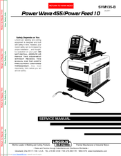
Lincoln Electric POWER WAVE 455 Service Manual (182 pages)
Lincoln Electric Welder User Manual
Brand:
Lincoln Electric
| Category:
Welding System
| Size: 3.36 MB
Table of Contents
Master for All Sections
6
Service Manual
1
Safety
2
Electric Shock Can Kill
3
Table of Contents
6
Installation
8
Technical Specifications - Power Feed 10 Wire Drive and Control Box
8
Technical Specifications - Power Wave 455
9
Safety Precautions
10
Location and Mounting
10
Stacking
10
Environment
10
Lifting
10
Feeder and Control Box Mounting
10
Electrical Connections
12
Grounding
12
High Frequency Interference Protection
12
Input Fuse and Supply Wire Considerations
12
Input Voltage Reconnect Procedure
12
Cable Connections
13
Control Cable Connections
13
Flexible Connection Possibilities
13
Cable Connections
14
Electrode and Work Leads - Electrode Positive Applications
14
Wire Feeder Setup
15
Electrode and Work Leads - Electrode Negative Applications
15
Voltage Sensing at the Workpiece
15
Wire Drive Gear Ratio (High or Low Speed
15
DIP Switch Setup
17
Gun and Cable Assemblies
21
GMAW Shielding Gas
21
Standard Panel Installation
22
-Operation Section-
23
Controls and Settings
23
Electrode Routing
23
Weld Mode Descriptions
23
Operation
24
Operating Instructions
24
Safety Instructions
24
System Description
24
Recommended Equipment
24
Controls and Settings
25
Duty Cycle and Welding Capabilities
25
Limitations
25
Power Wave Controls and Status Lights
25
Power Feed Controls
26
Display Control Panel
27
Weld Mode Descriptions
28
Electrode Routing
28
Arc Gouging
28
Board Level Adjustments
28
Constant Voltage (CV/MIG
28
Wire Reel Loading - Readi-Reels, Spools or Coils
29
Wire Spindle Placement
29
To Mount a 30 Lb (14 Kg) Readi-Reel Package (Using the Molded Plastic K363-P Readi-Reel Adapter) (Figure
29
Or 14 Lb (6 Kg) Innershield Coils (Figure
30
To Mount a 50 to 60 Lb (22.7 to 27.2 Kg) Coil (Using K1504-1 Coil Reel) (Figure
30
Feeding Electrode and Brake Adjustment
31
Drive Roll Kit Installation (KP1505
31
Drive Roll Pressure Setting
31
Procedure for Setting Angle of Feedplate
31
Wire Feed Overload Protection
32
-Accessories Section-
33
Power Wave Options and Accessories
33
Wire Feeder Options and Accessories
33
Accessories
34
General
34
Power Wave Options and Accessories
35
Wire Feeder Options and Accessories
35
Drive Roll and Guide Tube Kits
35
Factory Installed
35
Field Installed
35
Cable Receptacles
36
Input Cable Assemblies
36
Guns and Gun Adapters
38
Reel Adapters
38
Conduit Adapters
39
Chassis Options
40
Dual Procedure Switch Options
40
Gas and Water Kits
40
Description and Installation of Optional Control Box Panels
41
Periodic Maintenance
49
Routine Maintenance
49
Maintenance
50
Safety Precautions
50
Routine Maintenance
50
Periodic Maintenance
50
Theory of Operation
51
Modular Inverter Based Welding System
52
System Diagram a
52
Theory of Operation
52
Theory of Operation Section
52
System Diagram B
53
Theory of Operation
54
System Diagram C
54
Power Source General Description
55
Input Voltage and Precharge
55
Switch Boards and Main Transformer
56
Control Board
57
Output Rectifier and Choke
58
Thermal Protection
59
Protective Circuits
59
Over Current Protection
59
Under/Over Voltage Protection
59
Insulated Gate Bipolar Transistor (IGBT) Operation
60
Pulse Width Modulation
61
Maximum Output
61
Minimum Output
61
Control Box (User Interface
62
Power Feed 10 Feed Head
63
-Troubleshooting and Repair Section-
65
Component Replacement Procedures
65
PC Board Troubleshooting Procedures
65
Test Procedures
65
Troubleshooting Guide
65
How to Use Troubleshooting Guide
66
Troubleshooting and Repair
66
PC Board Troubleshooting Procedures
67
Troubleshooting Guide
69
Power Wave
69
Power Feed
77
Test Procedures
87
Input Filter Capacitor Discharge Procedure
87
Switch Board Test
89
Output Rectifier Test
93
Input Rectifier Test
95
Input Contactor Test
97
Auxiliary Transformer No. 2 Test
101
Auxiliary Transformer No. 1 Test
103
Power Board Test
107
Troubleshooting and Repair
109
Current Transducer Test
111
Drive Motor Test
115
Tach Feedback Test
117
Voltage Sense PC Board Test
119
Dual Encoder PC Board Test
121
Control Cable Continuity Test
123
Component Replacement Procedures
125
Gas Solenoid Removal and Replacement
125
Wire Feeder Control Board Removal and Replacement
127
Tach (Hall Effect) Assembly Removal and Replacement
129
Gear Box and Drive Motor Removal and Replacement
131
Switch Board and Filter Capacitor Removal and Replacement
135
Meter Accuracy Check
138
Control or Power Board Removal and Replacement
139
Auxiliary Transformer No. 1 Removal and Replacement Procedure
143
Main Input Contactor Removal and Replacement
147
Input Rectifier Removal and Replacement
151
Output Rectifier and Module Removal and Replacement
153
Power Source Error Interpretation Guide
157
Performance Troubleshooting Guide
158
Functional Troubleshooting Guide
159
-Electrical Diagrams Section-
160
Electrical Diagrams
162
Power Wave 455 Wiring Diagram - Code 10372
162
Power Wave 455 Wiring Diagram - Code 10555
163
Power Wave 455 Wiring Diagram - Code 10553
164
Power Feed 10 Control Box Wiring Diagram
165
Power Feed 10 Wire Drive Wiring Diagram
166
Power Feed 10 Machine Schematic
167
Power Wave 455 Machine Schematic - Code 10372
168
Power Wave 455 Machine Schematic - Code 10555
169
Power Wave 455 Machine Schematic - Code 10553
170
Power Wave 455 Control Pc Board Schematic (1
171
Power Wave 455 Control Pc Board Schematic (2
172
Power Wave 455 Power Pc Board Schematic
174
Power Wave 455 Input Pc Board Schematic
175
Power Wave 455 Switch Pc Board Schematic - Code 10372 & 10555
176
Power Wave 455 Switch Pc Board Schematic - Code 10553
177
Power Feed 10 Mother Control Pc Board Schematic
178
Power Feed 10 Control Pc Board Schematic
179
Power Feed 10 Display Pc Board Schematic
180
Power Feed 10 Encoder Pc Board Schematic
181
Power Feed 10 Voltage Sense Pc Board Schematic
182
Advertisement
Lincoln Electric POWER WAVE 455 Operator's Manual (33 pages)
Lincoln Electric Welder User Manual
Brand:
Lincoln Electric
| Category:
Welding System
| Size: 0.64 MB
Table of Contents
California Proposition 65 Warnings
2
Electric Shock Can Kill
3
Table of Contents
7
Installation
8
Technical Specifications - Power Wave 455
8
High Frequency Protection
9
Input Connection
9
Machine Grounding
9
Safety Precautions
9
Select Suitable Location
9
Stacking
9
Environmental Protection
9
Lifting
9
Input Fuse and Supply Wire Considerations
10
Output Connections
10
Power Wave / Power Feed Wire Feeder Interconnections
11
Electrode and Work Leads - Electrode Positive Applications
11
Electrode and Work Leads - Electrode Negative Applications
11
Control Cable Connections
11
Power Feed Control Box Mounting
12
Voltage Sensing at the Workpiece
11
Operating Instructions
13
Safety Instructions
13
Graphic Symbols that Appear on this Machine or in this Manual
14
Design Features and Advantages
15
General Description
15
Recommended Processes and Equipment
15
Compatible Lincoln Equipment
16
Limitations
16
Power Source Operation
16
Duty Cycle and Time Period
16
Case Front Controls
16
Welding Adjustments
17
Detailed Weld Mode Descriptions
17
Welding Capability
16
Operation
13
Accessories
19
Options / Accessories
19
Field Installed
19
Maintenance
20
Safety Precautions
20
Routine Maintenance
20
Troubleshooting
21
How to Use Troubleshooting Guide
22
Troubleshooting Guide
23
Lincoln Electric POWER WAVE 455 Operator's Manual (32 pages)
Lincoln Electric Home Safety Product User Manual
Brand:
Lincoln Electric
| Category:
Welding System
| Size: 0.56 MB
Table of Contents
Table of Contents
7
Installation
8
Technical Specifications - Power Wave 455
8
High Frequency Protection
9
Input Connection
9
Machine Grounding
9
Safety Precautions
9
Select Suitable Location
9
Stacking
9
Environmental Protection
9
Lifting
9
Input Fuse and Supply Wire Considerations
10
Input Voltage Reconnect Procedure
10
Output Connections
10
Power Wave / Power Feed Wire Feeder Interconnections
11
Electrode and Work Leads - Electrode Positive Applications
11
Electrode and Work Leads - Electrode Negative Applications
11
Control Cable Connections
11
Power Feed Control Box Mounting
12
Voltage Sensing at the Workpiece
11
Operating Instructions
13
Safety Instructions
13
Graphic Symbols that Appear on this Machine or in this Manual
14
Design Features and Advantages
15
General Description
15
Recommended Processes and Equipment
15
Compatible Lincoln Equipment
16
Limitations
16
Power Source Operation
16
Duty Cycle and Time Period
16
Case Front Controls
16
Welding Adjustments
17
Detailed Weld Mode Descriptions
17
Welding Capability
16
Operation
13
Accessories
19
Options / Accessories
19
Factory Installed
19
Field Installed
19
Maintenance
20
Safety Precautions
20
Routine Maintenance
20
Troubleshooting
21
How to Use Troubleshooting Guide
22
Troubleshooting Guide
23
Advertisement
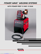
Lincoln Electric POWER WAVE 455 Brochure (12 pages)
Lincoln Electric Owner's Manual POWER WAVE WELDING SYSTEMS
Brand:
Lincoln Electric
| Category:
Welding System
| Size: 0.86 MB
Table of Contents
Technical Specifications
3
Power Source
3
A Closer Look
4
System Selection
4
Control Cables
10
Recommended Options
10
Advertisement
Related Products
Lincoln Electric POWER WAVE 11124
Lincoln Electric POWER WAVE 11226
Lincoln Electric POWER WAVE POWER WAVE WELDING SYSTEMS
Lincoln Electric POWER WAVE455M
Lincoln Electric POWER WAVE 355
Lincoln Electric POWER WAVE 345
Lincoln Electric INVERTEC POWER WAVE 450 ROBOTIC
Lincoln Electric POWER WAVE 405
Lincoln Electric POWER WAVE 455 STT
Lincoln Electric POWER-MIG 140C
Lincoln Electric Categories
Welding System
Welding Accessories
Flashlight
Wire Feeders
Portable Generator
More Lincoln Electric Manuals
Login
Sign In
OR
Sign in with Facebook
Sign in with Google
Upload manual
Upload from disk
Upload from URL