Intel S5500HCV Manuals
Manuals and User Guides for Intel S5500HCV. We have 6 Intel S5500HCV manuals available for free PDF download: Technical Product Specification, Service Manual, Configuration Manual, Spares Parts List & Configuration Manual
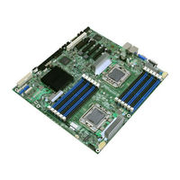
Intel S5500HCV Technical Product Specification (190 pages)
Product Specification
Brand: Intel
|
Category: Server Board
|
Size: 3.99 MB
Table of Contents
Advertisement
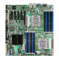
Intel S5500HCV Service Manual (66 pages)
Service Guide
Brand: Intel
|
Category: Server Board
|
Size: 2.1 MB
Table of Contents
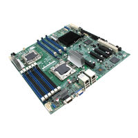
Intel S5500HCV Service Manual (66 pages)
Service Guide
Brand: Intel
|
Category: Server Board
|
Size: 2.09 MB
Table of Contents
Advertisement
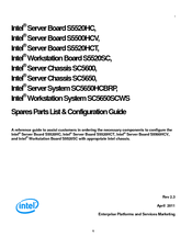
Intel S5500HCV Configuration Manual (31 pages)
Server / Workstation Board Server Chassis Server / Workstation System Spares Parts List & Configuration Guide
Brand: Intel
|
Category: Motherboard
|
Size: 1.1 MB
Table of Contents

Intel S5500HCV Spares Parts List & Configuration Manual (30 pages)
Brand: Intel
|
Category: Network Hardware
|
Size: 0.46 MB
Table of Contents

Intel S5500HCV Spares Parts List & Configuration Manual (24 pages)
Server Board, Workstation Board and Server Chassis
Brand: Intel
|
Category: Server Board
|
Size: 0.55 MB
Table of Contents
Advertisement