Sign In
Upload
Manuals
Brands
Garmin Manuals
GPS
GTN 6 series
Garmin GTN 6 series Manuals
Manuals and User Guides for Garmin GTN 6 series. We have
7
Garmin GTN 6 series manuals available for free PDF download: Maintenance Manual, System Maintenance Manual, Instructions Manual
Garmin GTN 6 series Maintenance Manual (163 pages)
Brand:
Garmin
| Category:
GPS
| Size: 7.24 MB
Table of Contents
Table of Contents
5
Content, Scope, and Purpose
10
Organization
10
Definitions and Abbreviations
11
Distribution
12
Publications
12
Table 1-1 Recommended Documents
12
2 System Description
13
Equipment Descriptions
14
GTN XI Navigators and GMA 35
14
NAV Antenna Cable Splitter
15
NAV Antenna Cable Diplexer
15
Backplate Connectors
16
Figure 2-1 GMA 35 Connector Layout Detail - Rear View
16
Figure 2-2 GMA 35C Bluetooth Connector Layout Detail - Front View
16
Figure 2-3 GTN 6XX XI Connector Layout Detail - Rear View
17
Figure 2-4 GTN 7XX XI Connector Layout Detail - Rear View
17
GTN XI Optional Interfaces
18
Figure 2-5 GTN System Interface Diagram
19
GTN Block Diagram
19
3 Control and Operation
20
Figure 3-1 GTN 650Xi Normal Mode Screen
21
Figure 3-2 GTN 750Xi Normal Mode Screen
21
GTN XI Normal Mode Overview
21
Figure 3-3 GTN 6XX XI and GTN 7XX XI Configuration Mode Pages
22
Updates
23
Figure 3-4 Software Update Installer
24
Figure 3-5 System and Software Version
24
Figure 3-6 Software Loader Card License Agreement
25
Figure 3-7 Software Loader Card Drive
25
Figure 3-8 Software Loader Card Progress Window
26
Figure 3-9 Software Loader Card Completion
26
Figure 3-10 System Information Page
30
System Information
30
Figure 3-11 GTN Setup Page
31
GTN Setup
31
Figure 3-12 GTN Options Pages
33
GTN Options
33
Figure 3-13 Terrain Configuration Page
34
Figure 3-14 Chart Configuration Page
35
Figure 3-15 COM Transmit Power Configuration Page
35
Figure 3-16 Weather Radar Page
36
Figure 3-17 Search and Rescue Configuration Page
37
Figure 3-18 GTN 6XX XI and GTN 7XX XI GTN Diagnostics Pages
38
GTN Diagnostics
38
GTN XI Configuration Mode Overview
22
Database Updates
40
Table 3-1 GTN XI Database Summary
40
4 Instructions for Continued Airworthiness
41
Maintenance Intervals
43
Table 4-1 Periodic Maintenance
43
Visual Inspection
45
Electrical Bonding Test
46
GTN XI Bonding Check (Metallic or Tube-And-Fabric Aircraft)
46
GTN XI Bonding Check (Composite Aircraft)
46
GMA 35 Bonding Check (Metallic or Tube-And-Fabric Aircraft)
47
GMA 35 Bonding Check (Composite Aircraft)
47
Flight Stream 210 Bonding Check (Metallic or Tube-And-Fabric Aircraft)
48
Flight Stream 210 Bonding Check (Composite Aircraft)
48
Transient Voltage Suppressor (TVS) (if Installed)
49
GTN XI TVS1 Check (GTN XI #1 Only)
49
Figure 4-1 TVS Assembly Check
50
GTN XI TVS2 Assembly Check (GTN XI #1 Only)
50
5 Troubleshooting
51
GTN XI General Troubleshooting
52
Table 5-1 GTN XI Troubleshooting Guide
52
Figure 5-1 Failure Example
56
GTN XI Failure Annunciations
56
GTN XI System Messages
57
Table 5-2 Alert Text Troubleshooting Guide
57
GTN XI System Related Alerts
57
Table 5-3 COM Alert Troubleshooting Guide
61
Table 5-4 GPS/SBAS Alert Troubleshooting Guide
63
Table 5-5 VLOC/GS Alert Troubleshooting Guide
64
Table 5-6 Remote Transponder Alert Troubleshooting Guide
65
Table 5-7 GAD 42 Alert Troubleshooting Guide
66
Table 5-8 Traffic Alert Troubleshooting Guide
66
Table 5-9 Weather Radar Alert Troubleshooting Guide
67
Table 5-10 Datalink Alert Troubleshooting Guide
68
Table 5-11 TAWS Alert Troubleshooting Guide
70
Table 5-12 Third-Party Sensor Alert Troubleshooting Guide
71
Flight Stream Troubleshooting
72
Table 5-13 Flight Stream Troubleshooting
72
GMA 35 Troubleshooting
74
Table 5-14 GMA 35 Troubleshooting
74
Figure 5-2 GMA 35 Failure Annunciation
75
GMA 35 Failure Annunciations
75
GMA 35 System Messages
75
Table 5-15 Remote Audio Panel Alert Troubleshooting Guide
75
6 Equipment Removal and Re-Installation
76
GTN XI
76
GTN XI
77
Figure 6-1 GTN 6XX Mounting Rack Assembly
78
Figure 6-2 GTN 7XX Mounting Rack Assembly
79
Table 6-1 Self-Test Values
80
Display of Self-Test Data
80
Gma 35
81
Figure 6-3 GMA 35 Mounting Rack Assembly Overview
82
Gma 35
82
Figure 6-4 GMA 35C Mounting Rack Assembly Overview
83
Data Card/Flight Stream 510
84
Figure 6-5 Flight Stream 210 Assembly Overview
85
Flight Stream 210
85
NAV Antenna Cable Diplexer
86
NAV Antenna Cable Splitter
86
Configuration Module (P1001 Only)
87
Table 6-2 Configuration Module Wire Color Reference Chart
87
Figure 6-6 Backshell Assembly (Potted Configuration Module)
88
Table 6-3 Configuration Module Kit P/N 011-00979-03 (P1001)
88
Figure 6-7 Backshell Assembly (Configuration Module with Spacer)
89
Table 6-4 Configuration Module Kit P/N 011-00979-00 (P1001)
89
Figure 6-8 Fan/Backplate Orientation (GTN 7XX XI)
90
GTN XI Fan
90
Table 6-5 Fan Kit
91
Table 6-6 Fan Cable Wire Color Reference Chart
91
Figure 6-9 Fan Wiring Replacement
92
TVS and Fuse (Nonmetallic Aircraft Only)
93
Fuse
93
Tvs
93
Figure 6-10 Tvs/Fuse Replacement (TVS1/F1)
94
Figure 6-11 Detail of TVS Pin Assembly
95
Figure 6-12 TVS2 Assembly
96
Figure 6-13 Instrument Panel Bonding
97
Instrument Panel Bonding Strap
97
Table 6-7 Instrument Panel Bonding Hardware
97
Flight Stream 210 Bonding Strap
98
Figure 6-14 Flight Stream Bonding
99
Table 6-8 Flight Stream Bonding Hardware
99
Interfaced Equipment Bonding Strap
100
Figure 6-15 Interfaced Equipment Bonding Strap (Metal Connectors)
101
Figure 6-16 Interfaced Equipment Bonding Strap (Non-Metal Connectors)
101
7 Equipment Configuration and Testing
102
GTN XI
102
Table 7-1 Configuration and Checkout Procedures
103
GTN XI
105
GTN XI Configuration Steps
105
GTN XI Ground Checks
105
Table 7-2 Summary of COM RX Squelch Settings and Auto Squelch Levels
106
Table 7-3 COM Carrier Squelch Selections
107
Table 7-4 COM Carrier Squelch Selections
107
Gma 35
108
GMA 35 Audio Panel Checkout (GTN 7XX XI Only)
108
GMA 35 Audio Panel Configuration (GTN 7XX XI Only)
108
Interfaced Equipment
112
Navigation Indicator
112
Displays
114
Serial Tuned DME
114
Transponder
118
Traffic or Weather System
119
Weather Radar
121
Fan Interface Check
122
Flight Stream 210/510 Interface Checks
122
Gdl 88
122
Configuration Module
124
Enabled Features
124
Terrain Configuration and Checks (for Units with Terrain Alerting/Taws Only)
124
8 Return to Service Procedure
125
Maintenance Records
125
Appendix A Aircraft-Specific Information
126
Advertisement
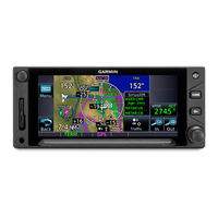
Garmin GTN 6 series Maintenance Manual (130 pages)
Part 27 AML STC
Brand:
Garmin
| Category:
Avionics Display
| Size: 7.23 MB
Table of Contents
Table of Contents
5
Organization
10
Scope
10
Unit Return
10
Abbreviations
11
Distribution
12
Publications
12
Table 1-1 GTN Related Publications
12
2 System Description
13
Equipment Descriptions
14
Gtn 6Xx
14
Gtn 7Xx
14
GMA 35/35C Audio Panel
14
Flight Stream 510
14
NAV Antenna Cable Splitter
15
NAV Antenna Cable Diplexer
15
HTAWS Annunciator
15
Cyclic Control Grip
15
GTN System Interfaces
16
GTN Optional Interfaces
16
Figure 2-1 GTN System Interface Diagram
17
GTN 6XX/7XX Interfaces
17
Figure 2-2 GTN 6XX/7XX Connector Layout Detail
18
Figure 2-3 GMA 35 System Interface Diagram
19
Figure 2-4 GMA 35 Rear Connectors
19
3 Gtn Control and Operation
20
Figure 3-1 GTN 6XX Control Features (GTN 650 Shown)
21
Figure 3-2 GTN 7XX Control Features (GTN 750 Shown)
21
GTN Controls
21
Figure 3-3 GTN Software Updater
22
GTN Software Loader Card Creation
22
Figure 3-4 System and Software Version
23
Figure 3-5 GTN Software Loader Card Formatting
23
Figure 3-6 Update Progress Window
23
Figure 3-7 Update Completion
24
GMA 35 Software Loading
24
GMA 35 Boot Block Loading
25
Software Loading
22
Figure 3-8 GTN 6XX and GTN 7XX Configuration Mode Pages
26
GTN Configuration Mode Overview
26
Figure 3-9 GTN 7XX Updates Page
27
GTN Software Updates
27
Figure 3-10 System Information Page
28
System Information
28
Figure 3-11 GTN 7XX GTN Setup Page
29
GTN Setup Page
29
Figure 3-12 GTN 7XX Options Page
31
GTN Options Page
31
Figure 3-13 GTN 7XX Terrain Configuration Page
32
Figure 3-14 Chart Configuration Page
33
Figure 3-15 COM Transmit Power Configuration Page
34
Figure 3-16 Search and Rescue Configuration Page
35
Figure 3-17 GTN 6XX and 7XX Diagnostics Pages
36
GTN Diagnostics Page
36
Database Updates
38
Table 3-1 GTN Database Summary
38
4 Troubleshooting
39
GTN General Troubleshooting
40
Table 4-1 GTN Troubleshooting Guide
40
Figure 4-1 Failure Screen
43
GTN Failure Annunciations
43
GTN System Messages
44
Table 4-2 Alert Text Troubleshooting Guide
44
GTN System Related Alerts
44
Table 4-3 COM Alert Troubleshooting Guide
46
Table 4-4 GPS/SBAS Alert Troubleshooting Guide
48
Table 4-5 VLOC/GS Alert Troubleshooting Guide
49
Table 4-6 Remote Transponder Alert Troubleshooting Guide
50
Table 4-7 Traffic Alert Troubleshooting Guide
51
Table 4-8 Data Link Alert Troubleshooting Guide
51
Table 4-9 HTAWS Alert Troubleshooting Guide
52
Table 4-10 Third-Party Sensor Alert Troubleshooting Guide
53
Flight Stream 510 Troubleshooting
54
Table 4-11 Flight Stream 510 Troubleshooting
54
Figure 4-2 GMA 35 Failure Annunciation
55
GMA 35 Failure Annunciations
55
Table 4-12 GMA 35 Troubleshooting Guide
56
GMA 35 Troubleshooting Guide
56
Table 4-13 Remote Audio Panel Alert Troubleshooting Guide
57
GMA 35 System Messages
57
GMA 35 Troubleshooting
55
5 Equipment Removal and Replacement
58
Gtn
59
Figure 5-1 GTN 7XX Mounting Rack Assembly
60
Figure 5-2 GTN 6XX Mounting Rack Assembly
62
Display of Self-Test Data
64
Table 5-1 Self-Test Values
64
Gma 35
65
Figure 5-3 GMA 35 Mounting Rack Assembly
66
Figure 5-4 GMA 35C Mounting Rack Assembly Overview
67
Data Card/Flight Stream 510
68
GPS/WAAS Antenna
68
NAV Antenna Cable Diplexer
69
NAV Antenna Cable Splitter
69
Configuration Module (P1001 Only)
70
Figure 5-5 Backshell Assembly
70
Table 5-2 Configuration Module Wire Color Reference Chart
70
Table 5-3 Configuration Module Kit P/N 011-00979-03 (P1001)
70
Figure 5-6 Fan Location on GTN Backplate (GTN 7XX Shown)
71
GTN Cooling Fan
71
Figure 5-7 Fan Wiring Installation
72
Table 5-4 Fan Kit
72
Table 5-5 Fan Cable Wire Color Reference Chart
72
6 Return to Service
73
Maintenance Records
75
Return to Service Procedures
76
Gtn 6Xx/7Xx
76
GTN Configuration Module
76
GTN Fan
76
Altitude Encoder/Air Data Computer/Fuel-Air Data Computer
77
GMA 35 (GTN 725/750 Only)
77
Navigation Indicator
77
Radar Altimeter
77
Traffic/Weather System
77
Transponder
77
Flight Stream 510
78
GTN Configuration and Testing
79
COM Configuration Page (GTN 635/650/750 Only)
79
Connector Engagement Check
79
Receiver/Transmitter Operation (GTN 635/650/750 Only)
80
Signal Acquisition Check
80
COM RX Squelch Check (GTN 635/650/750 Only)
81
Table 6-1 Summary of COM RX Squelch Settings and Auto Squelch Levels
81
Table 6-1 COM Carrier Squelch Selections
82
Table 6-2 COM Carrier Squelch Selections
82
Figure 6-1 Audio Panel Configuration Page
83
GMA 35 Audio Panel Configuration (GTN 7XX Only)
83
GMA 35 Configuration and Testing
83
GMA 35 Interface Check (GTN 7XX Only)
84
COM Transceiver Operational Check
85
Failsafe Operation Check
85
Alert Audio Check
86
ICS Check
86
NAV Audio Check
86
Music System Check (if Installed)
87
Telligence™ Voice Command Check (if Installed)
87
Interfaced Equipment Configuration and Checkout
88
Figure 6-2 Main Indicator (Analog) Configuration Page
89
Main Indicator (Analog) Configuration Page
89
Figure 6-3 VOR/LOC/GS Configuration Page
90
Navigation Indicator Configuration and Checkout
89
VOR/LOC/GS Configuration Page (GTN 650/750 Only)
90
Main Indicator Check (Analog Only)
91
VOR/LOC/GS Indicator
91
Display
92
Figure 6-4 XPDR1 Configuration Page
93
Remote Transponder Configuration
93
Transponder
93
Transponder Interface Check
94
Traffic or Weather System
95
Ryan TCAD Traffic System Interface Check
95
ARINC 429 Traffic System Interface Check
95
TIS (Garmin GTX 33/330) Interface Check
95
Fan Interface Check
96
Flight Stream 510 Interface Checks
96
Bluetooth Setup
96
Flight Stream to GTN Interface Check
96
Radar Altimeter Interface Check
96
Enabled Features
97
Figure 6-5 Audio Configuration Page
98
Figure 6-6 Terrain Configuration Page
98
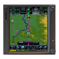
Garmin GTN 6 series Maintenance Manual (160 pages)
Part 23 AML STC
Brand:
Garmin
| Category:
Car Navigation system
| Size: 9.85 MB
Table of Contents
Table of Contents
6
Content, Scope and Purpose
11
Organization
11
Definitions and Abbreviations
12
Publications
13
Distribution
14
2 System Description
15
Equipment Descriptions
15
Backplate Connectors
16
Figure 2-1. GMA 35 Connector Layout Detail - Rear View
16
Figure 2-2. GTN 650 Connector Layout Detail - Rear View
16
Figure 2-3. GTN 750 Connector Layout Detail - Rear View
17
GTN Optional Interfaces
18
GTN Block Diagram
19
Figure 2-4. GTN System Interface Diagram
19
3 Gtn Control and Operation
21
GTN Controls
21
GTN Normal Mode Overview
21
Figure 3-1. GTN 6XX Normal Mode Screen
21
Figure 3-2. GTN 7XX Normal Mode Screen
21
Software Loading
22
Figure 3-3. GTN Software Updater
22
Through
22
Figure 3-4. System and Software Version
23
Figure 3-5. GTN Software Loader Card Formatting
23
Figure 3-6. Update Progress Window
24
Figure 3-7. Update Completion
24
GTN Configuration Mode Overview
26
Figure 3-8. GTN 6XX and GTN 7XX Configuration Mode Pages
26
Figure 3-9. GTN 7XX Updates Page
27
Figure 3-10. System Information Page
28
Figure 3-11. GTN 7XX Setup Pages
29
Figure 3-12. GTN 7XX Options Pages
31
Figure 3-13. GTN 7XX TAWS Configuration Page
32
Figure 3-14. Chart Configuration Page
33
Figure 3-15. COM Transmit Power Configuration Page
34
Figure 3-16. Weather Radar Page
35
Figure 3-17. GTN 6XX and 7XX Diagnostics Pages
37
Database Updates
39
Table 3-1. GTN Database Summary
39
4 Instructions for Continued Airworthiness
41
Airworthiness Limitations
41
Servicing Information
41
Maintenance Intervals
42
Table 4-1. Periodic Maintenance
42
Visual Inspection
43
Electrical Bonding Test
44
Transient Voltage Suppressor (TVS) (if Installed)
46
Figure 4-1. TVS Assembly Check
47
GPS/SBAS Antenna Cable Overbraid Inspection (if Installed)
48
WXR HSDB Cable Overbraid Inspection (if Installed)
48
5 Troubleshooting
49
GTN General Troubleshooting
49
Table 5-1. GTN Troubleshooting Guide
49
GTN Failure Annunciations
53
Figure 5-1. Failure Screen
53
GTN System Messages
54
Table 5-2. Alert Text Troubleshooting Guide
54
Table 5-3. COM Alert Troubleshooting Guide
57
Table 5-4. GPS/SBAS Alert Troubleshooting Guide
59
Table 5-5. VLOC/GS Alert Troubleshooting Guide
60
Table 5-6. Remote Transponder Alert Troubleshooting Guide
61
Table 5-7. GAD 42 Alert Troubleshooting Guide
62
Table 5-8. Traffic Alert Troubleshooting Guide
62
Table 5-9. Database Alert Troubleshooting Guide
63
Table 5-10. Weather Radar Alert Troubleshooting Guide
64
Table 5-11. TAWS Alert Troubleshooting Guide
65
Table 5-12. Third-Party Sensor Alert Troubleshooting Guide
66
GMA 35 Troubleshooting
67
Table 5-13. GMA 35 Troubleshooting
67
GMA 35 Failure Annunciations
68
GMA 35 System Messages
68
Figure 5-2. GMA 35 Failure Annunciation
68
Table 5-14. Remote Audio Panel Alert Troubleshooting Guide
68
6 Equipment Removal and Reinstallation
69
Gtn
69
Figure 6-1. GTN 7XX Mounting Rack Assembly
70
Figure 6-2. GTN 6XX Mounting Rack Assembly
71
Table 6-1. Self Test Values
72
Gma 35
73
Figure 6-3. GMA 35 Mounting Rack Assembly Overview
74
SD Card
75
NAV Antenna Cable Diplexer
76
NAV Antenna Cable Splitter
77
Configuration Module (P1001 Only)
78
Table 6-2. Configuration Module Wire Color Reference Chart
78
Figure 6-4. Backshell Assembly (Potted Configuration Module)
79
Table 6-3. Configuration Module Kit 011-00979-03 (P1001)
79
Figure 6-5. Backshell Assembly (Configuration Module with Spacer)
80
Table 6-4. Configuration Module Kit 011-00979-00 (P1001)
80
GTN Fan
81
Figure 6-6. Fan/Backplate Orientation (GTN 7XX)
81
Table 6-5. Fan Kit
82
Table 6-6. Fan Cable Wire Color Reference Chart
82
Figure 6-7. Fan Wiring Replacement
83
TVS and Fuse (Nonmetallic Aircraft Only)
84
Figure 6-8. Tvs/Fuse Replacement (TVS1/F1)
85
Figure 6-9. Detail of TVS Pin Assembly
86
Figure 6-10. TVS2 Assembly
87
GPS/SBAS Antenna Cable Overbraid
88
Figure 6-11. GPS/SBAS Antenna Cable Overbraid
89
WXR HSDB Cable Overbraid
91
Figure 6-12. WXR HSDB Cable Overbraid Details
95
7 Equipment Configuration and Testing
97
Gtn 6Xx/7Xx
97
Table 7-1. Configuration and Checkout Procedures
98
Gma 35
102
Figure 7-1. Audio Panel Page
102
Configuration Module
106
Interfaced Equipment
106
Figure 7-2. Main Indicator (Analog) Configuration Page
106
Figure 7-3. VOR/LOC/GS Configuration Page
107
Figure 7-4. XPDR1 Configuration Page
114
Enabled Features
119
Figure 7-5. Audio Configuration Page
119
Figure 7-6. TAWS Configuration Page
119
System Return to Service Procedure
121
Appendix A Aircraft Specific Information
123
Advertisement
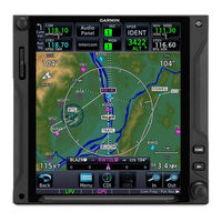
Garmin GTN 6 series System Maintenance Manual (142 pages)
Part 23 AML STC
Brand:
Garmin
| Category:
Avionics Display
| Size: 11.12 MB
Table of Contents
Table of Contents
6
1 Introduction
11
Content, Scope and Purpose
11
Organization
11
Definitions and Abbreviations
12
Publications
13
Distribution
14
2 System Description
15
Equipment Descriptions
15
Backplate Connectors
16
Figure 2-1. GMA 35 Connector Layout Detail - Rear View
16
Figure 2-2. GTN 650 Connector Layout Detail - Rear View
16
Figure 2-3. GTN 750 Connector Layout Detail - Rear View
17
GTN Optional Interfaces
18
GTN Block Diagram
19
Figure 2-4. GTN System Interface Diagram
19
3 Gtn Control and Operation
21
GTN Controls
21
GTN Normal Mode Overview
21
Figure 3-1. GTN 6XX Normal Mode Screen
21
Figure 3-2. GTN 7XX Normal Mode Screen
21
Through
22
Software Loading
22
Figure 3-3. GTN Software Updater
22
Figure 3-4. System and Software Version
23
Figure 3-5. GTN Software Loader Card Formatting
23
Figure 3-6. Update Progress Window
24
Figure 3-7. Update Completion
24
GTN Configuration Mode Overview
26
Figure 3-8. GTN 6XX and GTN 7XX Configuration Mode Pages
26
Figure 3-9. GTN 7XX Updates Page
27
Figure 3-10. System Information Page
28
Figure 3-11. GTN 7XX Setup Pages
29
Figure 3-12. GTN 7XX Options Pages
31
Figure 3-13. GTN 7XX TAWS Configuration Page
32
Figure 3-14. Chart Configuration Page
33
Figure 3-15. COM Transmit Power Configuration Page
34
Figure 3-16. Weather Radar Page
35
Figure 3-17. GTN 6XX and 7XX Diagnostics Pages
37
Database Updates
39
Table 3-1. GTN Database Summary
39
4 Instructions for Continued Airworthiness
41
Airworthiness Limitations
41
Servicing Information
41
Maintenance Intervals
42
Table 4-1. Periodic Maintenance
42
Visual Inspection
43
Electrical Bonding Test
44
Transient Voltage Suppressor (TVS) (if Installed)
46
Figure 4-1. TVS Assembly Check
47
GPS/WAAS Antenna Cable Overbraid Inspection (if Installed)
48
WXR HSDB Cable Overbraid Inspection (if Installed)
48
5 Troubleshooting
49
GTN General Troubleshooting
49
Table 5-1. GTN Troubleshooting Guide
49
GTN Failure Annunciations
53
Figure 5-1. Failure Screen
53
GTN System Messages
54
Table 5-2. Alert Text Troubleshooting Guide
54
Table 5-3. COM Alert Troubleshooting Guide
57
Table 5-4. GPS/SBAS Alert Troubleshooting Guide
59
Table 5-5. VLOC/GS Alert Troubleshooting Guide
60
Table 5-6. Remote Transponder Alert Troubleshooting Guide
61
Table 5-7. GAD 42 Alert Troubleshooting Guide
62
Table 5-8. Traffic Alert Troubleshooting Guide
62
Table 5-9. Database Alert Troubleshooting Guide
63
Table 5-10. Weather Radar Alert Troubleshooting Guide
64
Table 5-11. TAWS Alert Troubleshooting Guide
65
Table 5-12. Third-Party Sensor Alert Troubleshooting Guide
66
GMA 35 Troubleshooting
67
Table 5-13. GMA 35 Troubleshooting
67
GMA 35 Failure Annunciations
68
GMA 35 System Messages
68
Figure 5-2. GMA 35 Failure Annunciation
68
Table 5-14. Remote Audio Panel Alert Troubleshooting Guide
68
6 Equipment Removal and Reinstallation
69
Gtn
69
Figure 6-1. GTN 7XX Mounting Rack Assembly
70
Figure 6-2. GTN 6XX Mounting Rack Assembly
71
Table 6-1. Self Test Values
72
Gma 35
73
Figure 6-3. GMA 35 Mounting Rack Assembly Overview
74
SD Card
75
NAV Antenna Cable Diplexer
76
NAV Antenna Cable Splitter
77
Configuration Module (P1001 Only)
78
Table 6-2. Configuration Module Wire Color Reference Chart
78
Figure 6-4. Backshell Assembly (Potted Configuration Module)
79
Table 6-3. Configuration Module Kit 011-00979-03 (P1001)
79
Figure 6-5. Backshell Assembly (Configuration Module with Spacer)
80
Table 6-4. Configuration Module Kit 011-00979-00 (P1001)
80
GTN Fan
81
Figure 6-6. Fan/Backplate Orientation (GTN 7XX)
81
Table 6-5. Fan Kit
82
Table 6-6. Fan Cable Wire Color Reference Chart
82
Figure 6-7. Fan Wiring Replacement
83
TVS and Fuse (Nonmetallic Aircraft Only)
84
Figure 6-8. Tvs/Fuse Replacement (TVS1/F1)
85
Figure 6-9. Detail of TVS Pin Assembly
86
Figure 6-10. TVS2 Assembly
87
GPS/SBAS Antenna Cable Overbraid
88
Figure 6-11. GPS/SBAS Antenna Cable Overbraid
89
WXR HSDB Cable Overbraid
91
Figure 6-12. WXR HSDB Cable Overbraid Details
95
7 Equipment Configuration and Testing
97
Gtn 6Xx/7Xx
97
Table 7-1. Configuration and Checkout Procedures
98
Connector Engagement Check
100
Enabled Features
100
Gma 35
102
Figure 7-1. Audio Panel Page
102
Configuration Module
106
Interfaced Equipment
106
Figure 7-2. Main Indicator (Analog) Configuration Page
106
Figure 7-3. VOR/LOC/GS Configuration Page
107
Figure 7-4. XPDR1 Configuration Page
114
Enabled Features
119
Figure 7-5. Audio Configuration Page
119
Figure 7-6. TAWS Configuration Page
119
8 System Return to Service Procedure
121
Maintenance Records
121
Appendix A Aircraft Specific Information
123
General Information
123
Table A-1. General Information about Installation
123
Configuration Log
124
Wire Routing
131
Aircraft Wiring Diagrams
133
Equipment Location
133
Table A-2. Equipment Locations
133
Equipment Interfaced to the GTN 6XX/7XX
134
Table A-3. GTN #1 Interfaced Equipment
135
Table A-4. GTN #2 Interfaced Equipment
137
A.7 Equipment Interfaced to the GMA 35
139
Table A-5. Equipment Interfaced to the GMA 35 Audio Panel
139
Garmin GTN 6 series Maintenance Manual (106 pages)
Part 27 AML STC
Brand:
Garmin
| Category:
GPS
| Size: 8.04 MB
Table of Contents
Table of Contents
5
1 Introduction
9
Scope
9
Unit Return
9
Organization
9
Abbreviations
10
Publications
10
Table 1-1. GTN Related Publications
10
Distribution
11
2 System Description
13
Equipment Descriptions
13
Gtn 6Xx
13
Gtn 7Xx
13
GMA 35 Audio Panel
13
NAV Antenna Cable Splitter
13
NAV Antenna Cable Diplexer
13
HTAWS Annunciator
14
Cyclic Control Grip
14
GTN System Interfaces
14
GTN Optional Interfaces
14
GTN 6XX/7XX Interfaces
15
Figure 2-1. GTN System Interface Diagram
15
Figure 2-2. GTN 6XX/7XX Connector Layout Detail (GTN 650 and 750 Shown)
16
GMA 35 Equipment Interfaces
17
Figure 2-3. GMA 35 System Interface Diagram
17
Figure 2-4. GMA 35 Rear Connectors
17
3 Gtn Control and Operation
19
GTN Controls
19
Figure 3-1. GTN 6XX Control Features (GTN 650 Shown)
19
Figure 3-2. GTN 7XX Control Features (GTN 750 Shown)
19
Software Loading
20
GTN Software Loader Card Creation
20
Figure 3-3. GTN Software Updater
20
Figure 3-4. System and Software Version
20
Figure 3-5. GTN Software Loader Card Formatting
21
Figure 3-6. Update Progress Window
21
Figure 3-7. Update Completion
21
GMA 35 Software Loading
22
GTN Configuration Mode Overview
23
Figure 3-8. GTN 6XX and GTN 7XX Configuration Mode Pages
23
Figure 3-9. GTN 7XX Updates Page
24
GTN Software Updates
24
Figure 3-10. System Information Page
25
Figure 3-11. GTN 7XX Setup Page
25
GTN Setup Page
25
System Information
25
Figure 3-12. GTN 7XX Options Page
27
Figure 3-13. GTN 7XX Terrain Configuration Page
27
GTN Options Page
27
Figure 3-14. Chart Configuration Page
28
Figure 3-15. COM Transmit Power Configuration Page
29
Figure 3-16. GTN 6XX and 7XX Diagnostics Pages
30
GTN Diagnostics Page
30
Database Updates
32
Table 3-1. GTN Database Summary
32
4 Troubleshooting
33
GTN General Troubleshooting
33
Table 4-1. GTN Troubleshooting Guide
33
GTN Failure Annunciations
36
Figure 4-1. Failure Screen
36
GTN System Messages
37
GTN System Related Alerts
37
Table 4-2. Alert Text Troubleshooting Guide
37
Table 4-3. COM Alert Troubleshooting Guide
39
Table 4-4. GPS/SBAS Alert Troubleshooting Guide
41
Table 4-5. VLOC/GS Alert Troubleshooting Guide
42
Table 4-6. Remote Transponder Alert Troubleshooting Guide
43
Table 4-7. Traffic Alert Troubleshooting Guide
44
Table 4-8. Database Alert Troubleshooting Guide
44
Table 4-9. HTAWS Alert Troubleshooting Guide
45
Table 4-10. Third-Party Sensor Alert Troubleshooting Guide
46
GMA 35 Troubleshooting
47
GMA 35 Failure Annunciations
47
Figure 4-2. GMA 35 Failure Annunciation
47
GMA 35 Troubleshooting Guide
48
GMA 35 System Messages
48
Table 4-11. GMA 35 Troubleshooting Guide
48
Table 4-12. Remote Audio Panel Alert Troubleshooting Guide
48
5 Equipment Removal and Reinstallation
49
Gtn
49
Figure 5-1. GTN 7XX Mounting Rack Assembly
51
Figure 5-2. GTN 6XX Mounting Rack Assembly
53
Display of Self-Test Data
55
Table 5-1. Self Test Values
55
Gma 35
56
Figure 5-3. GMA 35 Mounting Rack Assembly Overview
57
SD Card
58
GPS/WAAS Antenna
58
NAV Antenna Cable Diplexer
58
NAV Antenna Cable Splitter
59
Configuration Module (P1001 Only)
59
Table 5-2. Configuration Module Wire Color Reference Chart
59
Table 5-3. Configuration Module Kit 011-00979-03 (P1001)
59
Figure 5-4. Backshell Assembly (Potted Configuration Module)
60
GTN Fan
61
Figure 5-5. Fan/Backplate Orientation (GTN 7XX Backplate Shown)
62
Table 5-4. Fan Kit
62
Table 5-5. Fan Cable Wire Color Reference Chart
62
Figure 5-6. Fan Wiring Installation
63
6 Return to Service
65
Maintenance Records
65
Return-To-Service Procedures
65
Gtn 6Xx/7Xx
65
GTN Configuration Module
66
GTN Fan
66
GMA 35 (GTN 725/750 Only)
66
Navigation Indicator
66
Transponder
66
Altitude Encoder/Air Data Computer/Fuel-Air Data Computer
66
Traffic/Weather System
66
Radar Altimeter
67
Configuration and Testing Procedures
67
GTN 6XX/7XX Configuration and Testing
67
GTN Ground Checks
67
GMA 35 Configuration and Testing
69
Figure 6-1. Audio Panel Configuration Page
69
Interfaced Equipment Configuration and Checkout
72
Navigation Indicator Configuration and Checkout
72
Figure 6-2. Main Indicator (Analog) Configuration Page
73
Figure 6-3. VOR/LOC/GS Configuration Page
73
Transponder
74
Figure 6-4. XPDR1 Configuration Page
75
Traffic or Weather System
76
Fan Interface Check
77
Radar Altimeter Interface Check
77
Enabled Features
77
HTAWS Configuration and Checks (for Units with HTAWS Only)
77
Figure 6-5. Audio Configuration Page
77
Figure 6-6. Terrain Configuration Page
77
Appendix Aaircraft Specific Information
79
Audio Panel
98
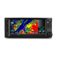
Garmin GTN 6 series Instructions Manual (22 pages)
Instructions for Continued Airworthiness For MD 369E; MD 369F; MD 369FF
Brand:
Garmin
| Category:
Avionics Display
| Size: 1.48 MB
Table of Contents
Table of Contents
3
1 Introduction
4
Purpose
4
Scope
4
Document Control
4
Permission to Use Certain Documents
4
Definitions
4
Terminology
4
2 Instructions for Continued Airworthiness
5
Introduction
5
Description of Alteration
5
Control, Operation, and Testing Information
6
Servicing Information
6
Periodic Maintenance
6
Table 1 Maintenance Intervals for Gtns GMA 35, and Flight Stream 510
6
Table 2 Maintenance Intervals for Antennas Installed under this STC
9
Troubleshooting Information
10
Removal and Replacement Information
10
Equipment Location and Access
11
GTN STC Installation Equipment Layout
11
GTN Navigator Installation
12
Table 3 Bill of Materials for GTN Navigators and Optional GMA Audio Panel
12
Circuit Breaker and HTAWS Annunciator Installation
14
Table 4 GTN Circuit Breaker Labels
14
Table 5 Bill of Materials for Circuit Breaker in MD369 Series
15
Table 6 Bill of Materials for HTAWS Annunciators in MD369 Series
16
Wire Routing
17
Weight and Balance
18
Table 7 Typical Weight and Balance of GTN and GMA 35 Installed in MD369 Series
18
Diagrams
19
Special Inspection Requirements
19
Application of Protective Treatments
19
Data Relative to Structural Fasteners
19
Special Tools
19
Additional Instructions
19
Overhaul Period
19
ICA Revision and Distribution
20
Assistance
20
Implementation and Record Keeping
20
3 Airworthiness Limitations Section
21
Appendix Aequipment Locations and Wire Routing
22
Garmin GTN 6 series Instructions Manual (24 pages)
Eurocopter EC130 Series
Brand:
Garmin
| Category:
GPS
| Size: 2.2 MB
Table of Contents
Table of Contents
3
1 Introduction
4
Purpose
4
Scope
4
Document Control
4
Permission to Use Certain Documents
4
Definitions
4
Terminology
5
2 Instructions for Continued Airworthiness
6
Introduction
6
Description of Alteration
6
Control, Operating, and Testing Information
7
Servicing Information
7
Periodic Maintenance
7
Table 1. Maintenance Intervals for Gtns and GMA 35
7
Table 2. Maintenance Intervals for Antennas Replaced under this STC
10
Troubleshooting Information
11
Removal and Replacement Information
11
Table 3. Bill of Materials
13
Table 4. Circuit Breaker Labels
18
Diagrams
21
Special Inspection Requirements
21
Application of Protective Treatments
21
Data Relative to Structural Fasteners
22
Special Tools
22
Additional Instructions
22
Overhaul Period
22
ICA Revision and Distribution
22
Assistance
22
Implementation and Record Keeping
22
3 Airworthiness Limitations Section
23
Appendix Aequipment Locations and Wire Routing
24
Advertisement
Related Products
Garmin GTN 625
Garmin GTN 635
Garmin GTN 650
Garmin GTN 625Xi
Garmin GTN 635Xi
Garmin GTN 650Xi
Garmin GTN 750
Garmin GTN 725
Garmin GTN 725Xi
Garmin GTN 750Xi
Garmin Categories
GPS
Watch
Car Navigation system
Avionics Display
Marine GPS System
More Garmin Manuals
Login
Sign In
OR
Sign in with Facebook
Sign in with Google
Upload manual
Upload from disk
Upload from URL