Sign In
Upload
Manuals
Brands
Daikin Manuals
Heat Pump
RKS50G2V1B
Daikin RKS50G2V1B Manuals
Manuals and User Guides for Daikin RKS50G2V1B. We have
7
Daikin RKS50G2V1B manuals available for free PDF download: Service Manual, Service Manual Field, Installation Manual
Daikin RKS50G2V1B Service Manual (316 pages)
G-Series
Brand:
Daikin
| Category:
Heat Pump
| Size: 10.53 MB
Table of Contents
Table of Contents
4
Introduction
8
Safety Cautions
8
Used Icons
12
Part 1 List of Functions
13
Functions
14
Cooling Only
14
Heat Pump
15
Part 2 Specifications
17
Specifications
18
Cooling Only
18
Specifications
19
Heat Pump
21
Part 3 Printed Circuit Board Connector Wiring Diagram
29
Printed Circuit Board Connector Wiring Diagram
30
Indoor Unit
30
Outdoor Unit
33
Part 4 Function and Control
41
Main Functions
42
Frequency Principle
42
Airflow Direction Control
44
Fan Speed Control for Indoor Units
45
Program Dry Operation
46
Automatic Operation
47
Thermostat Control
48
NIGHT SET Mode
49
ECONO Operation
50
2-Area INTELLIGENT EYE Operation
51
INTELLIGENT EYE Operation
53
Inverter POWERFUL Operation
54
Other Functions
55
Function of Thermistor
56
Control Specification
57
Mode Hierarchy
57
Frequency Control
58
Controls at Mode Changing / Start-Up
60
Discharge Pipe Temperature Control
62
Input Current Control
63
Freeze-Up Protection Control
65
Heating Peak-Cut Control
65
Outdoor Fan Control
66
Liquid Compression Protection Function
66
Defrost Control
67
Electronic Expansion Valve Control
68
Malfunctions
71
Forced Operation Mode
72
Standby Electricity Saving
72
Part 5 Operation Manual
73
System Configuration
74
Ftxs20/25/35/42/50G2V1B
75
Remote Control
75
Auto Dry Cool Heat Fan Operation
76
AUTO · DRY · COOL · HEAT · FAN Operation
76
Adjusting the Airflow Direction
78
COMFORT AIRFLOW and INTELLIGENT EYE Operation
80
POWERFUL Operation
83
OUTDOOR UNIT QUIET Operation
84
ECONO Operation
85
TIMER Operation
86
WEEKLY TIMER Operation
88
Atxs20/25/35/42/50G2V1B
93
Remote Control
93
Auto Dry Cool Heat Fan Operation
94
AUTO · DRY · COOL · HEAT · FAN Operation
94
Adjusting the Airflow Direction
96
COMFORT AIRFLOW Operation
98
INTELLIGENT EYE Operation
99
POWERFUL Operation
101
OUTDOOR UNIT QUIET Operation
102
ECONO Operation
103
TIMER Operation
104
Part 6 Service Diagnosis
106
Caution for Diagnosis
107
Troubleshooting with LED
107
Problem Symptoms and Measures
108
Service Check Function
109
ARC452 Series
109
ARC433 Series
112
Troubleshooting
115
Error Codes and Description
115
Indoor Unit PCB Abnormality
116
Freeze-Up Protection Control or Heating Peak-Cut Control
117
Fan Motor (DC Motor) or Related Abnormality
119
Thermistor or Related Abnormality (Indoor Unit)
121
Signal Transmission Error (between Indoor Unit and Outdoor Unit)
122
Unspecified Voltage (between Indoor Unit and Outdoor Unit)
123
Outdoor Unit PCB Abnormality
124
OL Activation (Compressor Overload)
126
Compressor Lock
127
DC Fan Lock
128
Input Overcurrent Detection
129
Four Way Valve Abnormality
130
Discharge Pipe Temperature Control
132
High Pressure Control in Cooling
134
Compressor System Sensor Abnormality
136
Position Sensor Abnormality
138
DC Voltage / Current Sensor Abnormality (20/25/35/42 Class)
141
CT or Related Abnormality (50 Class)
142
Thermistor or Related Abnormality (Outdoor Unit)
144
Electrical Box Temperature Rise
146
Radiation Fin Temperature Rise
148
Output Overcurrent Detection
150
Refrigerant Shortage
152
Low-Voltage Detection or Over-Voltage Detection
155
Signal Transmission Error on Outdoor Unit PCB
157
(50 Class Only)145
157
Signal Transmission Error on Outdoor Unit PCB (50 Class Only)
157
Check
158
How to Check
158
Four Way Valve Performance Check
159
Thermistor Resistance Check
160
Installation Condition Check
161
Discharge Pressure Check
161
Outdoor Fan System Check
162
Power Supply Waveforms Check
162
Capacitor Voltage Check
163
Power Module Check
163
Rotation Pulse Check on the Outdoor Unit Pcb
164
Main Circuit Short Check
165
Indoor Unit
167
Removal of Air Filter
167
Removal of Front Panel
169
Removal of Front Grille
171
Removal of Horizontal Blades / Vertical Blades
174
Removal of Electrical Box
177
Removal of PCB
180
Removal of Indoor Heat Exchanger
185
Removal of Swing Motors
188
Removal of Fan Motor
192
Outdoor Unit - RK(X)S20-35G2V1B, ARXS20-35G2V1B
195
Removal of Outer Panels / Fan Motor
195
Removal of Electrical Box
204
Removal of Thermistors
208
Removal of PCB
210
Removal of Reactor / Partition Plate
213
Removal of Sound Blanket
215
Removal of Four Way Valve
216
Removal of Compressor
219
Outdoor Unit - RK(X)S20-35G2V1B9
221
Removal of Outer Panels / Fan Motor
221
Outdoor Unit - RK(X)S20-35G2V1B9, ARXS20-35G3V1B
221
Removal of Electrical Box
230
Removal of PCB
233
Removal of Reactor / Partition Plate
241
Removal of Sound Blanket
243
Removal of Four Way Valve
245
Removal of Compressor
248
Outdoor Unit - RK(X)S42G2V1B, ARXS42G2V1B
250
Removal of Outer Panels
250
Removal of Electrical Box
252
Removal of PCB
257
Removal of Sound Blanket
262
Removal of Outdoor Fan / Fan Motor
264
Removal of Thermistors
267
Removal of Four Way Valve / Electronic Expansion Valve
268
Removal of Compressor
271
Outdoor Unit - RK(X)S50G2V1B, ARXS50G2V1B
274
Removal of Outer Panels
274
Removal of Outdoor Fan / Fan Motor
278
Removal of Electrical Box
282
Removal of PCB
287
Removal of Sound Blanket / Thermistors
290
Removal of Four Way Valve
292
Removal of Electronic Expansion Valve
293
Removal of Compressor
294
Trial Operation
298
Part 8 Trial Operation and Field Settings
298
Trial Operation
299
Field Settings
300
Field Settings
301
Model Type Setting
301
When 2 Units Are Installed in 1 Room
301
Standby Electricity Saving
302
Facility Setting Jumper and Switch (Cooling at Low Outdoor Temperature)
303
Jumper and Switch Settings
303
Jumper and Switch Settings
304
Application of Silicon Grease to a Power Transistor and a Diode Bridge
305
Part 9 Appendix
306
Piping Diagrams
307
Indoor Unit
307
Outdoor Unit
308
Outdoor Unit
311
Wiring Diagrams
312
Indoor Unit
312
Advertisement
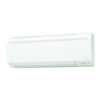
Daikin RKS50G2V1B Service Manual (283 pages)
Inverter Pair
Brand:
Daikin
| Category:
Air Conditioner
| Size: 11.85 MB
Table of Contents
Table of Contents
3
Introduction
7
Safety Cautions
7
Used Icons
11
Part 1 List of Functions
12
Functions
13
Cooling Only
13
Heat Pump
16
Part 2 Specifications
19
Specifications
20
Cooling Only
20
Heat Pump
25
Part 3 Printed Circuit Board Connector Wiring Diagram
30
Printed Circuit Board Connector Wiring Diagram
31
Indoor Unit
31
Outdoor Unit
33
Part 4 Function and Control
41
Main Functions
42
Temperature Control
42
Frequency Principle
42
Airflow Direction Control
44
Fan Speed Control for Indoor Units
45
Program Dry Operation
46
Automatic Operation
47
Thermostat Control
48
NIGHT SET Mode
49
ECONO Operation
50
Inverter POWERFUL Operation
51
Other Functions
52
Function of Thermistor
53
Control Specification
54
Mode Hierarchy
54
Frequency Control
55
Controls at Mode Changing / Start-Up
57
Discharge Pipe Temperature Control
59
Input Current Control
60
Freeze-Up Protection Control
61
Heating Peak-Cut Control
61
Outdoor Fan Control
62
Liquid Compression Protection Function
62
Defrost Control
63
Electronic Expansion Valve Control
64
Malfunctions
67
Forced Operation Mode
68
Standby Electricity Saving
68
Part 5 Operation Manual
69
System Configuration
70
Operation Manual
71
Names of Parts
71
AUTO · DRY · COOL · HEAT · FAN Operation
74
Adjusting the Airflow Direction
76
POWERFUL Operation
78
OUTDOOR UNIT QUIET Operation
79
ECONO Operation
80
TIMER Operation
81
WEEKLY TIMER Operation
83
Part 6 Service Diagnosis
88
Caution for Diagnosis
89
Troubleshooting with LED
89
Problem Symptoms and Measures
90
Service Check Function
91
ARC452 Series
91
Troubleshooting
94
Error Codes and Description
94
Indoor Unit PCB Abnormality
95
Freeze-Up Protection Control or Heating Peak-Cut Control
96
Fan Motor (DC Motor) or Related Abnormality
98
Thermistor or Related Abnormality (Indoor Unit)
100
Signal Transmission Error (between Indoor Unit and Outdoor Unit)
101
Unspecified Voltage (between Indoor Unit and Outdoor Unit)
102
Outdoor Unit PCB Abnormality
103
OL Activation (Compressor Overload)
105
Compressor Lock
106
DC Fan Lock
107
Input Overcurrent Detection
108
Four Way Valve Abnormality
109
Discharge Pipe Temperature Control
111
High Pressure Control in Cooling
112
Compressor System Sensor Abnormality
114
Position Sensor Abnormality
116
DC Voltage / Current Sensor Abnormality (25/35 Class)
119
CT or Related Abnormality (50 Class)
120
Thermistor or Related Abnormality (Outdoor Unit)
122
Electrical Box Temperature Rise
124
Radiation Fin Temperature Rise
127
Output Overcurrent Detection
130
Refrigerant Shortage
132
Low-Voltage Detection or Over-Voltage Detection
135
Signal Transmission Error on Outdoor Unit PCB (50 Class Only)
137
Check
138
How to Check
138
Part 7 Removal Procedure
147
Indoor Unit
148
Removal of Air Filter / Front Panel / Front Grille
148
Removal of Horizontal Blade
152
Removal of Electrical Box
153
Removal of PCB
155
Removal of Vertical Blades
159
Removal of Heat Exchanger
162
Removal of Fan Rotor / Fan Motor
163
Outdoor Unit - RK(X)S25/35F2V1B
165
Removal of Outer Panels / Fan Motor
165
Removal of Electrical Box
174
Removal of PCB
178
Removal of Reactor / Partition Plate
180
Removal of Sound Blanket
182
Removal of Four Way Valve
183
Removal of Compressor
186
Outdoor Unit - RK(X)S25/35G2V1B
188
Removal of Outer Panels / Fan Motor
188
Removal of Electrical Box
197
Removal of Thermistors
201
Removal of PCB
203
Removal of Reactor / Partition Plate
206
Removal of Sound Blanket
208
Removal of Four Way Valve
209
Removal of Compressor
212
Outdoor Unit - RK(X)S25/35G2V1B9
214
Removal of Outer Panels / Fan Motor
214
Removal of Electrical Box
223
Removal of PCB
226
Removal of Reactor / Partition Plate
234
Removal of Sound Blanket
236
Removal of Four Way Valve
238
Removal of Compressor
241
Outdoor Unit - RK(X)S50F2V1B, RK(X)S50G2V1B
243
Removal of Outer Panels
243
Removal of Outdoor Fan / Fan Motor
247
Removal of Electrical Box
251
Removal of PCB
256
Removal of Sound Blanket / Thermistors
259
Removal of Four Way Valve
261
Removal of Electronic Expansion Valve
262
Removal of Compressor
263
Part 8 Trial Operation and Field Settings
266
Trial Operation
267
Field Settings
268
Model Type Setting
268
When 2 Units Are Installed in 1 Room
269
Standby Electricity Saving
270
Facility Setting Jumper and Switch (Cooling at Low Outdoor Temperature)
271
Jumper and Switch Settings
272
Application of Silicon Grease to a Power Transistor and a Diode Bridge
273
Part 9 Appendix
274
Piping Diagrams
275
Indoor Unit
275
Outdoor Unit
276
Wiring Diagrams
279
Indoor Unit
279
Outdoor Unit
280
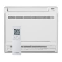
Daikin RKS50G2V1B Service Manual Field (150 pages)
C-Series Inverter Pair Duct Connected Type
Brand:
Daikin
| Category:
Air Conditioner
| Size: 3.68 MB
Table of Contents
Table of Contents
3
Part 1 List of Functions
3
Part 3 Printed Circuit Board Connector Wiring Diagram
3
Part 5 Operation Manual
3
Introduction
6
Safety Cautions
6
Used Icons
10
Part 1 List of Functions
11
Functions
12
Part 2 Specifications
15
Specifications
16
Cooling Only
16
Heat Pump
19
Part 3 Printed Circuit Board Connector Wiring Diagram
22
Printed Circuit Board Connector Wiring Diagram
23
Indoor Unit
23
Outdoor Unit
25
Part 4 Function and Control
27
Main Functions
28
Temperature Control
28
Frequency Principle
28
Fan Speed Control for Indoor Units
30
Program Dry Operation
31
Automatic Operation
32
Thermostat Control
33
NIGHT SET Mode
34
HOME LEAVE Operation
35
Inverter POWERFUL Operation
36
Other Functions
37
Function of Thermistor
38
Control Specification
39
Mode Hierarchy
39
Frequency Control
40
Controls at Mode Changing / Start-Up
42
Discharge Pipe Temperature Control
43
Input Current Control
44
Freeze-Up Protection Control
45
Heating Peak-Cut Control
45
Outdoor Fan Control
46
Liquid Compression Protection Function
46
Defrost Control
47
Electronic Expansion Valve Control
48
Malfunctions
51
Part 5 Operation Manual
52
System Configuration
53
Operation Manual
54
Remote Controller
54
AUTO · DRY · COOL · HEAT · FAN Operation
55
To Change the Air Flow Rate Setting
56
POWERFUL Operation
57
OUTDOOR UNIT QUIET Operation
58
HOME LEAVE Operation
59
TIMER Operation
61
To Use on Timer Operation
62
To Combine on Timer and off Timer
62
Part 6 Service Diagnosis
63
Caution for Diagnosis
64
Troubleshooting with LED
64
Problem Symptoms and Measures
65
Service Check Function
66
Troubleshooting
69
Error Codes and Description
69
Indoor Unit PCB Abnormality
70
Freeze-Up Protection Control or Heating Peak-Cut Control
71
Fan Motor (AC Motor) or Related Abnormality
73
Thermistor or Related Abnormality (Indoor Unit)
74
Signal Transmission Error (between Indoor Unit and Outdoor Unit)
75
Unspecified Voltage (between Indoor Unit and Outdoor Unit)
76
Outdoor Unit PCB Abnormality
77
OL Activation (Compressor Overload)
78
Compressor Lock
79
DC Fan Lock
80
Input Overcurrent Detection
81
Four Way Valve Abnormality
82
Discharge Pipe Temperature Control
84
High Pressure Control in Cooling
85
Compressor System Sensor Abnormality
86
Position Sensor Abnormality
87
CT or Related Abnormality
89
Thermistor or Related Abnormality (Outdoor Unit)
91
Electrical Box Temperature Rise
93
Radiation Fin Temperature Rise
95
Output Overcurrent Detection
97
Refrigerant Shortage
99
Low-Voltage Detection or Over-Voltage Detection
101
Signal Transmission Error (on Outdoor Unit PCB)
102
Check
103
How to Check
103
Four Way Valve Performance Check
104
Thermistor Resistance Check
105
Installation Condition Check
106
Discharge Pressure Check
106
Outdoor Fan System Check
107
Power Supply Waveforms Check
107
Capacitor Voltage Check
108
Power Module Check
108
Hall IC Check
111
Part 7 Removal Procedure
112
Outdoor Unit
113
Removal of Outer Panels
113
Removal of Outdoor Fan / Fan Motor
117
Removal of Electrical Box
121
Removal of PCB
126
Removal of Sound Blanket / Thermistors
129
Removal of Four Way Valve
131
Removal of Electronic Expansion Valve
132
Removal of Compressor
133
Part 8 Trial Operation and Field Settings
136
Pump down Operation
137
Forced Cooling Operation Mode
138
Trial Operation
139
Field Settings
140
When 2 Units Are Installed in 1 Room
140
Facility Setting Switch (Cooling at Low Outdoor Temperature)
141
Jumper and Switch Settings
141
Application of Silicon Grease to a Power Transistor and a Diode Bridge
142
Part 9 Appendix
143
Piping Diagrams
144
Indoor Unit
144
Outdoor Unit
145
Wiring Diagrams
146
Indoor Unit
146
Outdoor Unit
147
Advertisement
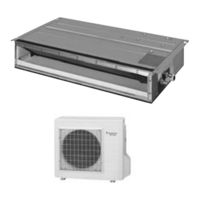
Daikin RKS50G2V1B Service Manual (149 pages)
C-Series Inverter Pair Duct Connected Type
Brand:
Daikin
| Category:
Air Conditioner
| Size: 1.86 MB
Table of Contents
Table of Contents
4
Introduction
7
Safety Cautions
7
Used Icons
11
Part 1 List of Functions
13
Functions
14
Part 2 Specifications
17
Specifications
18
Cooling Only
18
Heat Pump
21
Part 3 Printed Circuit Board Connector Wiring Diagram
24
Printed Circuit Board Connector Wiring Diagram
25
Indoor Unit
25
Outdoor Unit
27
Part 4 Function and Control
29
Main Functions
30
Temperature Control
30
Frequency Principle
30
Fan Speed Control for Indoor Units
32
Program Dry Operation
33
Automatic Operation
34
Thermostat Control
35
NIGHT SET Mode
36
HOME LEAVE Operation
37
Inverter POWERFUL Operation
38
Other Functions
39
Function of Thermistor
40
Control Specification
41
Mode Hierarchy
41
Frequency Control
42
Controls at Mode Changing / Start-Up
44
Discharge Pipe Temperature Control
45
Input Current Control
46
Freeze-Up Protection Control
47
Heating Peak-Cut Control
47
Outdoor Fan Control
48
Liquid Compression Protection Function
48
Defrost Control
49
Electronic Expansion Valve Control
50
Malfunctions
53
Forced Operation Mode
54
Part 5 Operation Manual
55
System Configuration
56
Operation Manual
57
Remote Control
57
Auto Dry Cool Heat Fan Operation
58
AUTO · DRY · COOL · HEAT · FAN Operation
58
To Change the Air Flow Rate Setting
59
POWERFUL Operation
60
OUTDOOR UNIT QUIET Operation
61
HOME LEAVE Operation
62
TIMER Operation
64
To Use on Timer Operation
65
To Combine on Timer and off Timer
65
Part 6 Service Diagnosis
66
Caution for Diagnosis
67
Troubleshooting with LED
67
Problem Symptoms and Measures
68
Service Check Function
69
Troubleshooting
72
Error Codes and Description
72
Indoor Unit PCB Abnormality
73
Freeze-Up Protection Control or Heating Peak-Cut Control
74
Fan Motor (AC Motor) or Related Abnormality
76
Thermistor or Related Abnormality (Indoor Unit)
77
Signal Transmission Error (between Indoor Unit and Outdoor Unit)
78
Unspecified Voltage (between Indoor Unit and Outdoor Unit)
79
Outdoor Unit PCB Abnormality
80
OL Activation (Compressor Overload)
81
Compressor Lock
82
DC Fan Lock
83
Input Overcurrent Detection
84
Four Way Valve Abnormality
85
Discharge Pipe Temperature Control
87
High Pressure Control in Cooling
88
Compressor System Sensor Abnormality
89
Position Sensor Abnormality
90
CT or Related Abnormality
92
Thermistor or Related Abnormality (Outdoor Unit)
94
Electrical Box Temperature Rise
96
Radiation Fin Temperature Rise
98
Output Overcurrent Detection
100
Refrigerant Shortage
102
Low-Voltage Detection or Over-Voltage Detection
104
Signal Transmission Error (on Outdoor Unit PCB)
105
Check
106
How to Check
106
Four Way Valve Performance Check
107
Thermistor Resistance Check
108
Installation Condition Check
109
Discharge Pressure Check
109
Outdoor Fan System Check
110
Power Supply Waveforms Check
110
Capacitor Voltage Check
111
Power Module Check
111
Hall IC Check
112
Part 7 Removal Procedure
113
Outdoor Unit
114
Removal of Outer Panels
114
Removal of Outdoor Fan / Fan Motor
118
Removal of Electrical Box
122
Removal of PCB
127
Removal of Sound Blanket / Thermistors
130
Removal of Four Way Valve
132
Removal of Electronic Expansion Valve
133
Removal of Compressor
134
Part 8 Trial Operation and Field Settings
137
Trial Operation
138
Field Settings
139
When 2 Units Are Installed in 1 Room
139
Facility Setting Switch (Cooling at Low Outdoor Temperature)
140
Jumper and Switch Settings
140
Application of Silicon Grease to a Power Transistor and a Diode Bridge
141
Part 9 Appendix
142
Piping Diagrams
143
Indoor Unit
143
Outdoor Unit
144
Wiring Diagrams
145
Indoor Unit
145
Outdoor Unit
146
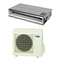
Daikin RKS50G2V1B Service Manual (147 pages)
Inverter Pair Duct Connected Type C-Series
Brand:
Daikin
| Category:
Air Conditioner
| Size: 3.76 MB
Table of Contents
Table of Contents
3
Part 1 List of Functions
3
Part 3 Printed Circuit Board Connector Wiring Diagram
3
Introduction
6
Safety Cautions
6
Used Icons
10
Part 1 List of Functions
11
Functions
12
Part 2 Specifications
15
Specifications
16
Cooling Only
16
Heat Pump
19
Part 3 Printed Circuit Board Connector Wiring Diagram
22
Printed Circuit Board Connector Wiring Diagram
23
Indoor Unit
23
Outdoor Unit
25
Part 4 Function and Control
27
Main Functions
28
Temperature Control
28
Frequency Principle
28
Fan Speed Control for Indoor Units
30
Program Dry Operation
31
Automatic Operation
32
Thermostat Control
33
NIGHT SET Mode
34
HOME LEAVE Operation
35
Inverter POWERFUL Operation
36
Other Functions
37
Function of Thermistor
38
Control Specification
39
Mode Hierarchy
39
Frequency Control
40
Controls at Mode Changing / Start-Up
42
Discharge Pipe Temperature Control
43
Input Current Control
44
Freeze-Up Protection Control
45
Heating Peak-Cut Control
45
Outdoor Fan Control
46
Liquid Compression Protection Function
46
Defrost Control
47
Electronic Expansion Valve Control
48
Malfunctions
51
Forced Operation Mode
52
Part 5 Operation Manual
53
System Configuration
54
Operation Manual
55
Remote Controller
55
AUTO · DRY · COOL · HEAT · FAN Operation
56
To Change the Air Flow Rate Setting
57
POWERFUL Operation
58
OUTDOOR UNIT QUIET Operation
59
HOME LEAVE Operation
60
TIMER Operation
62
To Use on Timer Operation
63
To Combine on Timer and off Timer
63
Part 6 Service Diagnosis
64
Caution for Diagnosis
65
Troubleshooting with LED
65
Problem Symptoms and Measures
66
Service Check Function
67
Troubleshooting
70
Error Codes and Description
70
Indoor Unit PCB Abnormality
71
Freeze-Up Protection Control or Heating Peak-Cut Control
72
Fan Motor (AC Motor) or Related Abnormality
74
Thermistor or Related Abnormality (Indoor Unit)
75
Signal Transmission Error (between Indoor Unit and Outdoor Unit)
76
Unspecified Voltage (between Indoor Unit and Outdoor Unit)
77
Outdoor Unit PCB Abnormality
78
OL Activation (Compressor Overload)
79
Compressor Lock
80
DC Fan Lock
81
Input Overcurrent Detection
82
Four Way Valve Abnormality
83
Discharge Pipe Temperature Control
85
High Pressure Control in Cooling
86
Compressor System Sensor Abnormality
87
Position Sensor Abnormality
88
CT or Related Abnormality
90
Thermistor or Related Abnormality (Outdoor Unit)
92
Electrical Box Temperature Rise
94
Radiation Fin Temperature Rise
96
Output Overcurrent Detection
98
Refrigerant Shortage
100
Low-Voltage Detection or Over-Voltage Detection
102
Signal Transmission Error (on Outdoor Unit PCB)
103
Check
104
How to Check
104
Four Way Valve Performance Check
105
Thermistor Resistance Check
106
Installation Condition Check
107
Discharge Pressure Check
107
Outdoor Fan System Check
108
Power Supply Waveforms Check
108
Capacitor Voltage Check
109
Power Module Check
109
Hall IC Check
110
Part 7 Removal Procedure
111
Outdoor Unit
112
Removal of Outer Panels
112
Removal of Outdoor Fan / Fan Motor
116
Removal of Electrical Box
120
Removal of PCB
125
Removal of Sound Blanket / Thermistors
128
Removal of Four Way Valve
130
Removal of Electronic Expansion Valve
131
Removal of Compressor
132
Part 8 Trial Operation and Field Settings
135
Trial Operation
136
Field Settings
137
When 2 Units Are Installed in 1 Room
137
Facility Setting Switch (Cooling at Low Outdoor Temperature)
138
Jumper and Switch Settings
138
Application of Silicon Grease to a Power Transistor and a Diode Bridge
139
Part 9 Appendix
140
Piping Diagrams
141
Indoor Unit
141
Outdoor Unit
142
Wiring Diagrams
143
Indoor Unit
143
Outdoor Unit
144
Daikin RKS50G2V1B Service Manual (25 pages)
4.2/5.0/6.0/7.1 kW Class
Brand:
Daikin
| Category:
Air Conditioner
| Size: 2.79 MB
Table of Contents
Table of Contents
3
Removal of Outer Panels
4
Removal of Outdoor Fan / Fan Motor
7
Removal of Electrical Box
10
Removal of Pcbs
14
Removal of Sound Blankets / Thermistors
17
Removal of Four Way Valve
19
Removal of Electronic Expansion Valve
20
Removal of Compressor
21
Daikin RKS50G2V1B Installation Manual (15 pages)
Brand:
Daikin
| Category:
Air Conditioner
| Size: 1.67 MB
Table of Contents
Installation Manual
1
Safety Precautions
4
Precautions for Selecting the Location
5
Outdoor Unit Installation Drawings
6
Precautions on Installation
7
Outdoor Unit Installation
7
Installation Guidelines
7
Installing Outdoor Unit
7
Flaring the Pipe End
8
Refrigerant Piping
8
Purging Air and Checking Gas Leakage
9
Refrigerant Piping Work
10
Pump down Operation
11
Trial Operation and Testing
13
Test Items
13
Advertisement
Related Products
Daikin RKS20G2V1B
Daikin RKS20G2V1B9
Daikin RKS25G2V1B
Daikin RKS25G2V1B9
Daikin RKS35G2V1B
Daikin RKS35G2V1B9
Daikin RKS42G2V1B
Daikin RKM18PVMK
Daikin RKM24PVMK
Daikin RKM35PVMA
Daikin Categories
Air Conditioner
Heat Pump
Remote Control
Chiller
Fan
More Daikin Manuals
Login
Sign In
OR
Sign in with Facebook
Sign in with Google
Upload manual
Upload from disk
Upload from URL