Sign In
Upload
Manuals
Brands
Comtech EF Data Manuals
Media Converter
UT-4505E
Comtech EF Data UT-4505E Manuals
Manuals and User Guides for Comtech EF Data UT-4505E. We have
2
Comtech EF Data UT-4505E manuals available for free PDF download: Installation And Operation Manual
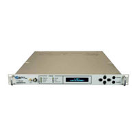
Comtech EF Data UT-4505E Installation And Operation Manual (208 pages)
C- and Ku-Band Up Converters
Brand:
Comtech EF Data
| Category:
Media Converter
| Size: 3.09 MB
Table of Contents
Table of Contents
5
Tables
16
Figures
17
About this Manual
19
Disclaimer
19
Preface
19
Conventions and References
20
Examples of Multi-Hazard Notices
20
Patents and Trademarks
20
Warnings, Cautions, Notes, and References
20
Electrical Installation
21
Electrical Safety and Compliance
21
Operating Environment
21
Recommended Standard Designations
21
Safety and Compliance
21
European Union Electromagnetic Compatibility (EMC) Directive (2004/108/EC)
22
European Union Radio Equipment and Telecommunications Terminal
22
European Union Low Voltage Directive (LVD) (2006/95/EC)
23
European Union Rohs Directive (2002/95/EC)
23
European Union Telecommunications Terminal Equipment Directive (91/263/EEC)
23
CE Mark
24
Comtech EF Data Headquarters
24
Product Support
24
Warranty Policy
24
Limitations of Warranty
25
Exclusive Remedies
26
Chapter 1. Introduction
27
Overview
27
Figure 1-1. UT-4500 Series up Converters (UT-4505 Shown)
27
Functional Description
28
Figure 1-2. UT-4500 Series up Converter Physical Configuration
28
Applications
29
RF Signal Conversion
30
Figure 1-3. Typical Functional Block Diagram (UT-4512 Shown)
30
Monitor & Control
31
Up Converter Features
32
Physical Description
32
Dimensional Envelope
33
Figure 1-4. UT-4500 Series up Converter Dimensional Envelope
33
Front Panel
34
Figure 1-5. Front Panel View (UT-4505 Shown)
34
Rear Panel
36
Figure 1-6. Rear Panel (with IOM) - Current Production Unit
36
Figure 1-7. Rear Panel (with TSM) - Initially Released Chassis (OBSOLETE)
36
Chapter 2. Specifications
39
Physical and Environmental Specifications
39
Regulatory Compliance
39
Physical Specifications
39
Mean Time between Failures (MTBF)
40
Temperature Range
40
Humidity (Non-Condensing)
40
Altitude
40
Front Panel Features
40
Sample Point Connectors
40
LED Monitoring
40
Keypad
41
Vacuum Fluorescent Display (VFD)
41
Rear Panel Features
41
Chassis Power, Fusing, and Grounding
41
Power Supply Input
41
Power Consumption
41
Fusing
41
Grounding
42
External Reference Connectors
42
Ethernet Connector
42
Serial Connectors
42
Removable "Personality" Modules
42
IOM (Input/Output Module) Assemblies
42
PSM (Polarity Switch Module) Assemblies
43
TSM (Transmit Switch Module) Assemblies
43
EQM (Equalizer Module) Assemblies
43
RSM (Receive Switch Module) Assemblies
44
Operational Specifications
44
Available Models / Operating Frequency Ranges
44
C-Band Units
44
Ku-Band Units
45
Conversion
45
Frequency Selection Step Size
45
Preset Channels
45
Stability over Time
45
Stability over Temperature
45
IF Input
46
Noise Figure
46
Level
46
Range
46
Impedance
46
Return Loss
46
RF Output
46
Output Level
46
Intermodulation
46
Carrier Mute
47
Non-Carrier Spurious
47
Carrier Spurious
47
AM to PM
47
Return Loss
47
Impedance
47
Transfer
47
Gain
47
Attenuation Adjustment
47
Gain Stability
48
Ripple
48
Slope
48
IF Bandwidth
48
Group Delay
48
Linear
48
Parabolic
48
Phase Noise
49
Ut-4505
49
Ut-4505/E, Ut-4505/F, Ut-4505/G, Ut-4505/H, Ut-4505/I, Ut-4505/J, Ut-4505/K, Ut-4505/M, Ut-4505/N
49
Ut-4514
49
Ut-4514/F, Ut-4518, Ut-4518/E
49
Chapter 3. Installation and Startup
51
Unpack and Inspect the Shipment
51
Figure 3-1. Unpack and Inspect the Shipment
51
Install the Unit into a Rack Enclosure
53
Figure 3-2. Install the Unit into a Rack Enclosure
54
Install the Optional Rear Support Brackets Kit
55
Figure 3-3. Install the Optional Rear-Mounting Support Brackets Kit
55
Install the Optional Rack Slide Set
57
Figure 3-4. Install the Optional Rack Slide Set
57
Connect Prime Power Connection
58
Connect External Cables
58
Overview - Cabling Connection Types
59
Coaxial Cable Connections
60
Figure 4-1. Coaxial Connector Examples
60
Type 'BNC
61
Type 'TNC
61
Type 'N
61
Type 'F
61
Type 'SMA
62
D-Subminiature Cable Connections
62
Figure 4-2. D-Subminiature Connector Examples
62
Cable Connections
63
Figure 4-3. RJ-45/RJ-48 Connector Example
63
USB Cable Connections
64
Figure 4-4. USB Connector Examples
64
Unit Connectors
65
Figure 4-5. UT-4500 Series Rear and Front Panels
65
Figure 4-6. UT-4500 Series Rear Panel - Initially Released Chassis (OBSOLETE)
65
Power Connections
66
Power Interface Module - Standard AC Unit
66
AC Operation - Replace the Fuses
66
Figure 4-7. Standard AC Power Module
66
Figure 4-8. Replace the AC Fuses
66
AC Operation - Apply AC Power
67
Figure 4-9. Apply AC Power to the Unit
67
Power Interface Module - Optional -48VDC Unit
68
DC Operation - Replace the Fuses
68
Figure 4-10. Optional DC Power Module
68
DC Operation - Apply Power
69
Unit Ground Connection
69
Figure 4-11. Apply DC Power to the Unit
69
Figure 4-12. Unit Ground Connection
69
Operational Connections
70
Figure 4-13. Rear Panel Operational Connections (with IOM)
70
Table 4-1. 'Ethernet' M&C Interface Connector Pinout
71
Table 4-4. 'J1 | COM1' EIA-232C Pinout
71
Table 4-5. 'P1 | RELAY' Pinout
72
Figure 4-14. Front Panel Sample Test Point Connections
72
UT-4500 Series Cable Connections
73
Figure 4-15. UT-4500 Series Cabling Example (with TSM)
73
Removable "Personality" Modules
74
Figure 4-16. "Personality" Module Examples
74
Removable Module Connectors
75
Table 4-6. 'J3 | HSB' Data Interface Pinout
75
Removable Module Operation in Non-Redundant (Standalone) Applications
76
Figure 4-17. UT-4500 Standalone Cabling Example to IOM
76
Figure 4-18. UT-4500 Standalone Cabling Example to TSM
76
Removable Module Operation in Redundant Applications
77
Figure 4-19. TSM Switching Schematic
77
Chapter 5. Firmware Update
79
Firmware Overview
79
UT-4500 Firmware Update Procedure Summary
79
About Firmware Numbers, File Versions, and Formats
80
Prepare for the Firmware Download
81
Required User-Supplied Items
81
Configure the Terminal Emulator Program
81
Get the UT-4500 Management IP Address and Firmware Information
81
Use the UT-4500 Front Panel to Get the Management IP Address and Firmware Information
82
Use the HTTP Interface to Find the Firmware Information
83
Use the Serial Interface to Find the Firmware Information
83
Make a Temporary Folder (Subdirectory) on the User PC
84
Use Windows Desktop to Make a Folder
84
Use Windows Explorer to Make a Folder
85
Use the Run and Browse Windows to Make a Folder
85
Use Windows Command-Line or Command Prompt to Make a Folder
86
Download and Extract the Firmware Update Files
87
Use Windows Desktop to View Folder Contents
89
Use Windows Command-Line to View Folder Contents
89
Upload the Firmware Files and Update the UT-4500 Unit
89
Important Considerations
89
Steps to "Creflash" Upload the Firmware Files
90
Steps to FTP Upload the Firmware Files
91
Steps to Complete the Firmware Update Procedure
91
Select the Boot Image
92
Use the Front Panel to Select the Boot Image
92
Use the HTTP Interface to Select the Boot Image
92
Reboot the Unit
92
Hard-Reboot the Unit from the Rear Panel
92
Soft-Reboot the Unit from the HTTP Interface
93
Chapter 6. Front Panel Operation
95
Front Panel Overview
95
Figure 6-1. Front Panel View (UT-4505 Shown)
95
Power up the Unit
96
Figure 6-2. Rear Panel - Standard and Optional Power Interfaces
96
LED Indicators
97
Vacuum Fluorescent Display (VFD)
98
Keypad
99
Front Panel Operation - Menu Matrix
100
Opening Screen
101
Main Menu
101
SELECT:) CONFIG (Configuration) Menu Branch
102
CONFIG:) OUTPUT Submenu
102
CONFIG:) OUTPUT Submenu (OPTIONAL DUAL if RACK MOUNT CONVERTERS)
103
CONFIG:) REMOTE (Remote Control) Submenu
104
REMOTE:) Local
104
Remote:) Serial
104
Remote:) Ethernet
105
Remote:) EthernetAddress
105
Remote:) EthernetGateway
105
Remote:) EthernetSnmp
106
CONFIG:) REDUNDANCY Submenu
108
Redundancy:) Mode
108
REDUNDANCY:) Auto/Manual
109
Redundancy:) Force
109
Redundancy:) Hsb
110
CONFIG:) COLDSTART Submenu
111
SELECT:) MONITOR Menu Branch
111
SELECT:) FAULTS Menu Branch
112
Faults:) Current
112
Faults:) Stored
113
Faults:) Stored View
113
Faults:) Mask
114
SELECT:) PRE-SELECTS Menu Branch
114
Pre-Selects:) Load
115
Pre-Selects:) Program
115
Pre-Selects:) Clear
116
SELECT:) UTILITY Menu Branch
116
UTILITY:) TIME (Real-Time Clock) Submenu
117
UTILITY:) DISP (VFD Display) Submenu
117
UTILITY:) FIRMWARE Submenu
117
Firmware:) Info
118
Firmware Info: BOOTROM
118
Firmware:) InfoImage#1/#2
118
Firmware:) Select
119
UTILITY:) AID (Application Identification String) Submenu
119
UTILITY:) SLOPE Submenu
121
UTILITY:) LAMP-TEST Submenu
121
Chapter 7. Ethernet Interface Operation
123
Overview
123
Prerequisites
124
SNMP Interface
124
Management Information Base (MIB) Files
124
DT-45Xx Common MIB File
125
DT-45Xx Traps MIB File
125
SNMP Community Strings
125
SNMP Traps
126
Telnet Interface
126
Figure 7-1. Telnet Interface Example - Windows Command-Line
126
Using Hyperterminal for Telnet Remote Control Operation
127
Figure 7-2. Telnet Interface Example - Hyperterminal
127
Configure Hyperterminal for Telnet Remote Control Operation
128
Figure 7-3. Configure Hyperterminal
128
HTTP (Web Server) Interface
129
HTTP Interface User Login
129
HTTP Interface Features
131
Menu Tree
131
Page Navigation
131
Page Sections
131
Action Buttons
132
Page Refresh
132
Drop-Down Lists
132
Text or Data Entry
132
HTTP Interface Page Examples and Descriptions
133
Home
133
Home | Home
133
Home | Contact
134
Home | Support
135
Admin (Administration)
136
Admin | Access
136
Admin | SNMP
138
Config (Configuration)
139
Config | Converter
139
Config | Ref
141
Config | Pre-Selects
142
Config | Utility
143
Config | Redundancy
145
Status
146
Status | Summary
146
Status | Faults
147
Overview
149
Communication Interfaces
149
Tia/Eia-485 (Rs-485)
149
Tia/Eia-232C (Rs-232C)
150
Ethernet (100BASE-TX)
150
Access Methods
151
Direct (Physical) Access
151
Indirect (Virtual) Access
151
Addresses
152
Physical Address
152
Virtual Address
152
IP Address
153
Basic Protocol
153
Transmission Mode
153
Baud Rate
154
Asynchronous Character Format
154
Character Set
154
Response Timeout
154
Bus Inactivity Requirement
154
Message Structure
155
Start Character
155
Device Address
155
Commands/Queries
155
Confirmation Response
156
Error Response
156
End of Message
156
Command Ending
156
Response Ending
156
Remote Operation - Commands/Queries
157
Command/Query Quick References
157
Utility Commands/Queries Quick Reference
157
Configuration Commands/Queries Quick Reference
158
Redundancy Commands/Queries Quick Reference
158
Status Commands/Queries Quick Reference
158
Stored Alarm Queries Quick Reference
159
Utility Commands/Queries
159
TIM (Time)
159
DAT (Date)
159
TPE (Time Protocol Enable)
160
TPS (Time Protocol Server)
160
LRS (Local / Remote Status)
160
MAC (Media Access Control Address)
161
IPA (IP Address)
161
IPG (IP Gateway)
161
SPA (Set Physical Address)
162
SBR (Set Baud Rate)
162
CON (Set LCD Contrast)
162
LCD (Set LCD Brightness)
163
SSM (Screen Saver Mode)
163
SST (Screen Saver Timeout)
163
VFD (VFD Brightness)
164
SRO (Set Reference Oscillator Tuning)
164
SSA (Converter Slope Adjustment)
164
RET (Equipment Type)
165
PNM (Part Number)
165
FRW (Legacy Firmware Information)
165
FRM (Firmware Information)
166
IMG (Firmware Image)
166
AID (Application Identification)
167
FRB (Force Reboot)
167
Configuration Commands / Queries
168
FRE (Frequency)
168
IFF (if Frequency)
168
ATT (Attenuation)
169
CLD (Cold Start)
169
MUT (RF Mute)
169
CMM (Configure Mute Mode)
170
CRM (Redundancy Mute Mode)
170
AFR (Auto Fault Recovery)
170
PGM (Program Pre-Select)
171
DPS (Display All Pre-Selects)
171
CLR (Clear Pre-Select Configuration)
172
SEL (Select Pre-Select Configuration)
172
Operating Modes
172
RED (Redundant Mode)
172
ICT (Initialize Chain Command)
173
SAM (Switching Automatic/Manual Mode)
173
FBU (Force Backup)
174
Status Queries
175
RCS (Configuration Status)
175
RMS (Maintenance Status)
175
RUS (Utility Status)
176
RAS (Alarm Status)
176
SAS (Summary Alarm Status)
176
TSC (Terminal Status Change)
177
PACRCS (Packed Configuration Status)
177
PACRMS (Packed Maintenance Status)
178
PACRAS (Packed Alarm Status)
178
PACRUS (Packed Utility Status)
179
Stored Alarms
180
TSA (Total Stored Alarms)
180
CAS (Clear All Stored Alarms)
180
LAA (List All Alarms)
180
Error Processing
181
General Errors
181
Configuration Errors
181
Mode Errors
181
Time-Outs
181
Appendix A. Redundant System Operation
183
Redundancy Overview
183
Backup Converter (BU
184
High Speed Bus (HSB
184
Removable "Personality" Modules
184
Converter Switching
184
Redundant Configurations
185
1:1 Redundant Systems
185
1:N Redundant Systems
188
Redundant System Configuration
191
Redundant System Configuration Using the Front Panel
191
Initial Configuration
191
Automatic Configuration Verification
192
Manual Configuration and Verification
194
Redundant System Configuration Using the UT-4500 HTTP Interface
196
Offset Adjustment
198
Redundancy Systems - Converter Management
198
Appendix B. Maintenance and Troubleshooting
199
Overview
199
Maintenance Testing
200
Sample Test Points
200
Troubleshooting
201
Converter Faults
201
Prime Power
201
DC Power Supply Module
201
RF Converter Module
202
Synthesizer Sum Loop Module
202
Synthesizer Fine Step Module
202
Reference Oscillator Module
202
Temperature Fault
203
Removable "Personality" Modules
203
Spares
204
Redundancy Systems - Converter Management
204
Remove a Faulted Converter
204
Install a Replacement Converter
205
Advertisement
Comtech EF Data UT-4505E Installation And Operation Manual (112 pages)
UT-4500 Series
Brand:
Comtech EF Data
| Category:
Media Converter
| Size: 1.3 MB
Table of Contents
Installation and Operation Manual
1
Customer Support
8
Table of Contents
9
Figures
13
About this Manual
15
Conventions and References
15
Metric Conversion
15
Recommended Standard Designations
15
Trademarks
15
EMC Compliance
16
Federal Communications Commission (FCC)
16
En 60950
17
Safety Compliance
17
Warranty Policy
18
Chapter 1. Introduction
19
Overview
19
Functional Description
20
Preface Revision
20
Figure 1. Front Panel (Model UT-4505 Shown)
20
Figure 2. Rear Panel (Shown with TSM Module)
20
Figure 3. Typical Functional Block Diagram (Model UT-4514 Shown)
21
Specifications
22
Table 1. UT-4505 C-Band up Converter Specifications
22
Table 2. UT-4505/E/F/G/H/J/X up Converter Specifications
24
Table 3. UT-4505I/M up Converter Specifications
26
Table 4. UT-4514 and UT-4514/C/D/E/F up Converter Specifications
28
Table 5. UT-4518 and UT-4518/E up Converter Specifications
30
Figure 4. UT-4514 Dimensional Envelope
32
Physical Configuration
33
Figure 5. Physical Configuration - up Converter
33
Front Panel Display
34
Front Panel Test Point Samples
34
Prime Power Switch
34
New in this Manual
34
Chapter 2. Installation
37
Unpacking and Inspection
37
Rack Mount Installation
37
Prime Power Connection
37
Cable Connections
38
Rear Panel Connections
38
Table 6. Rear Panel Connectors
38
EIA-485/EIA-232 Interface (COM 1), Connector J1
39
Table 7. J1, 2 Wire EIA-485 Interface Pin-Out
39
Table 8. J1, 4 Wire EIA-485 Interface Pin-Out
39
Table 9. J1, EIA-232 Interface Pin-Out
39
High Speed Bus (HSB), Connector J3
40
Summary Fault Output (RELAY), Connector P1
40
Table 10. J3, High Speed Bus Connector Pin-Out
40
Table 11. P1, Summary Fault Connector Pin-Out
40
Cable Connections for Non-Redundant System Operation
41
Cable Connections for Redundant System Operation
41
Figure 6. Cable Interconnect Diagram
41
Figure 7. Non-Redundant Converter Configuration
42
Figure 8. Non-Redundant Converter Configuration
42
Chapter 3. System Operation
43
Overview
43
Figure 9. Front Panel (Model UT-4505 Shown)
43
Figure 10. Rear Panel (with TSM Module and Optional REF Output)
43
Table 12. Operating Functions - Front Panel
44
Switching Power on
45
Operation
45
Figure 11. Keypad
45
Figure 12. Converter Operating Command Functions
46
Figure 13. Configuration Menu Commands - Redundancy off
47
Figure 14. Configuration Menu Commands - Redundancy ON, Backup Unit Not Selected
48
Figure 15. Configuration Menu Commands - Redundancy on and Backup Unit Selected
49
Figure 16. Pre-Select Menu Commands
50
Figure 17. Monitor Status Menu Commands
50
Figure 18. Current Faults Menu Commands
51
Figure 19. Stored Faults Menu Commands
51
Figure 20. Utility Function Menu Commands
52
Converter Commands
53
Configuration Functions Menu
54
Pre-Select Function Menu
54
Current Faults Function Menu
55
Monitor Status Function Menu
55
Stored Faults
56
Utility Function Menu
57
Chapter 4. Redundant System Operation
59
Overview
59
Backup Converter
60
High Speed Bus (HSB)
60
Detachable Modules
60
Redundant Configurations
61
Table 13. 4500 Series up Converter Configurations
61
Figure 21. 1:1 Redundant Configuration - Single Source if Input
62
Figure 22. 1:1 Redundant Configuration Diagram - Single Source
62
Figure 23. 1:1 Redundant Configuration Diagram - Single Source RF Input
63
Figure 24. TSEQM Block Diagram
63
Figure 25. 1:1 Redundant Configuration - Dual Source if Input
64
Figure 26 1:1 Redundant Configuration Diagram Dual Source if Input
64
Figure 27. 1:N Redundant Configuration with IOM-XX and TSM-XX Installed
65
Figure 28. 1:N Redundant Configuration Diagram with IOM-XX and TSM-XX Installed
66
Redundant System Configuration
67
Initial Configuration
67
Figure 29. 1:3 Front Panel Displays
67
Automatic Configuration Verification
68
Figure 30. 1:3 System in AUTO Redundant Mode
68
Figure 31. Converter #1 Being Backed up
69
Manual Configuration/Verification
70
Figure 32. Converter #1 in MANUAL, Others in AUTO
70
Figure 33. Forced BU of Converter #1
71
Offset Adjustment
72
Redundancy Systems - Converter Removal
72
Chapter 5. Remote Control
75
General
75
Protocol
75
Transmission Mode
75
Baud Rate
76
Format
76
Character Set
76
Response Timeout
76
Bus Inactivity Requirement
76
Access Methods
77
Direct Access
77
Indirect Access
77
Addresses
78
Physical Address
78
Virtual Address
78
Message Structure
79
Start Character
79
Device Address
79
Command
79
Confirmation Response
79
Error Response
80
End of Message
80
Command / Response Pairs
81
Utility Commands
81
Configuration Commands
84
Modes
87
Status Commands
89
Stored Alarm
93
Error Processing
95
General Errors
95
Configuration Errors
95
Mode Errors
95
Time-Outs
95
Converter Remote Command Summary
96
Table 14. Remote Command Summary
96
Chapter 6. Theory of Operation
99
Applications
99
RF Signal Conversion
100
Figure 34. Typical Converter Functional Block Diagram (Model UT-4514 Shown)
101
Monitor & Control
102
Chapter 7. Maintenance and Troubleshooting
103
Overview
103
Maintenance Testing
104
Test Point Samples
104
Figure 35. Converter Signal and Interconnecting Cable Diagram
104
Troubleshooting
105
Converter Faults
105
Converter I/O Modules
107
Spare
107
Index
109
Advertisement
Related Products
Comtech EF Data UT-4505F
Comtech EF Data UT-4505
Comtech EF Data UT-4505G
Comtech EF Data UT-4505H
Comtech EF Data UT-4505J
Comtech EF Data UT-4505I
Comtech EF Data UT-4505X
Comtech EF Data UT-4505/K
Comtech EF Data UT-4505/M
Comtech EF Data UT-4505/N
Comtech EF Data Categories
Modem
Switch
Amplifier
Network Router
Media Converter
More Comtech EF Data Manuals
Login
Sign In
OR
Sign in with Facebook
Sign in with Google
Upload manual
Upload from disk
Upload from URL