Sign In
Upload
Manuals
Brands
Comtech EF Data Manuals
Amplifier
HPOD
Comtech EF Data HPOD Manuals
Manuals and User Guides for Comtech EF Data HPOD. We have
2
Comtech EF Data HPOD manuals available for free PDF download: Installation And Operation Manual
Comtech EF Data HPOD Installation And Operation Manual (161 pages)
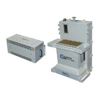
C, X, Ku-BandHigh Power Outdoor Amplifier
Brand:
Comtech EF Data
| Category:
Amplifier
| Size: 7.57 MB
Table of Contents
Table of Contents
3
List of Tables
7
List of Figures
8
About this Manual
11
Conventions and References
11
Disclaimer
11
Patents and Trademarks
11
Preface
11
Examples of Multi-Hazard Notices
12
Recommended Standard Designations
12
Warnings, Cautions, and Notes
12
Electrical Safety Notice
13
Installation Guidelines Regarding Power Line Quality
13
Comtech Headquarters
14
Limitations of Warranty
14
Product Support
14
Warranty Policy
14
Exclusive Remedies
15
Chapter 1. Introduction
17
Overview
17
Figure 1-1. Comtech HPOD SSPA
17
Features
18
Solid-State Advantage
18
Field-Replaceable Power Supply
18
Built-In Redundancy Controller
18
Phase Combining
18
Optional "Smart BUC" Functionality
18
Over Drive (Excessive RF Input Level) and OPS
19
Functional Description
19
Dimensional Envelope
20
Figure 1-2. HPOD SSPA Dimensional Envelope
20
Theory of Operation
21
Figure 1-3. Comtech HPOD SSPA Block Diagram
21
SSPA Module
22
Power Supply
22
Cooling System
22
Monitor and Control (M&C)
22
Block up Converter Input Option
23
Specifications
24
Chapter 2. External Connectors and Pinouts
28
Cabling Connection Types
28
Coaxial Cable Connections
28
Figure 2-1. Coaxial Connector Example
28
Circular Cable Connections
29
HPOD SSPA Cabling Connections
29
Figure 2-2. Circular Connector Example
29
Table 2-1. HPOD SSPA External Connectors
30
Figure 2-3. HPOD External Connectors
30
RF Signal Interface Connector Group
31
J1 | RF IN' Connector
31
J2 | RF OUT' Connector
31
Table 2-2. 'J2 | RF OUT' Waveguide Output Flange
31
Ground and Power Connection Group
32
Ground Connection
32
J3 | AC IN' Connector (AC Power Main)
32
Table 2-3. 'J3 | AC IN' Connector Pinout
32
J10' Connector: Optional -48V DC Power Supply
33
Table 2-4. 'J10 | DC' Connector Pinout
33
Electrical Control Interface Connection Group
34
J4 | REDUNDANT LOOP' Connector
34
Table 2-5. 'J4 | REDUNDANT LOOP' Connector Pinout
34
J6 | COM1' Connector
35
J8 | INPUT SAMPLE' Connector
35
J9 | OUTPUT SAMPLE' Connector
35
Table 2-6. 'J6 | COM1' Connector Pinout
35
Energize the HPOD SSPA
36
Figure 2-4. HPOD Unit
36
Chapter 3. Updating Firmware
38
Overview
38
Getting Started: Prepare for the Firmware Download
39
Download and Extract the Firmware Update
42
Perform the FTP Upload Procedures
45
Perform the Automated Serial-Based FTP Upload Procedure
46
Perform the Ethernet-Based FTP Upload Procedure
48
Chapter 4. Ethernet-Based Remote Product Management
53
Ethernet Management Interface Protocols
53
SNMP Interface
53
Management Information Base (MIB) Files
53
SNMP Community Strings
54
SNMP Traps
54
Telnet Interface
55
Telnet Operation Via Hyperterminal
56
HPOD Web Server (HTTP) Interface
57
Enable the Web Server Interface
57
User Login
59
Web Server Interface - Operational Features
60
Navigation
60
Page Sections
60
Action Buttons
60
Drop-Down Lists
60
Text or Data Entry
61
Web Server Interface - Menu Tree
61
Web Server
61
Home Page
62
Home | Home Page
62
Home | Contact and Home | Support
62
Figure 4-1. HPOD Home | Home Page
62
Admin
63
Admin | Access Page
63
Figure 4-2. Admin | Access Page
63
Admin | SNMP Page
65
Figure 4-3. Admin | SNMP Page
65
Config
66
Config | Amplifier Page
66
Figure 4-4. Config | Amplifier Page
66
Config | Utility Page
68
Figure 4-5. Config | Utility Page
68
Config | Redundancy Page
69
Figure 4-6. Config | Redundancy Page
69
Status
70
Status | Monitor Page
70
Figure 4-7. Status | Monitor Page
70
Status | Alarms Page
71
Figure 4-8. Status | Alarms Page
71
Status | Fets Page
72
Figure 4-9. Status | Fets Page
72
Chapter 5. Serial-Based Remote Product Management
74
Overview
74
Key Operational Parameters
74
RF Input Level
74
Attenuator Control
75
Mute Control
75
Faults
75
Power Detector
76
Most Common Remote Queries
76
Serial Remote-Control Introduction
76
Basic Protocol
77
Packet Structure
78
Start of Packet
79
Target Address
79
Address Delimiter
79
Instruction Code
79
Instruction Code Qualifier
80
Optional Message Arguments
81
End of Packet
81
Remote Commands and Queries
82
Appendix A. Redundancy System Assembly Kits
100
Overview
100
Table A-1. Summary of Available Redundancy System Assembly Kits
101
Common Mounting Kits
102
Universal Pole Mounting Kit (Comtech P/N PL/12319-1
102
Table A-2. Universal Pole Mounting Kit (Comtech P/N PL/12319-1) Parts List
102
Figure A-1. Universal Pole Mounting Kit (CE Comtech FD P/N PL/12319-1
103
Unit Mounting Kit (Comtech P/N PL/12300-1
104
Table A-3. Unit Mounting Kit (Comtech P/N PL/12300-1) Parts List
104
Figure A-2. Unit Mounting Kit (Comtech P/N PL/12300-1
105
1:1 Unistrut Kit (Comtech P/N KT/12200-1
106
Table A-4. 1:1 Redundancy System - Unistrut Kit (Comtech P/N KT/12200-1) Parts List
106
Figure A-3. 1:1 Redundancy System - Unistrut Kit (Comtech P/N KT/12200-1
107
1:2 Unistrut Kit (Comtech P/N KT-0000017
108
Table A-5. 1:2 Redundancy System - Unistrut Kit (Comtech P/N KT-0000017) Parts List
108
Figure A-4. 1:2 Redundancy System - Unistrut Kit (Comtech P/N KT-0000017
109
1:1 or 1:2 Free Standing Unistrut Kit (Comtech P/N KT-0020827
110
Table A-6. 1:1 or 1:2 Redundancy System - Free Standing Unistrut Kit (Comtech P/N KT-0020827) Parts List
110
Figure A-5. 1:1 or 1:2 Redundancy System - Free Standing Unistrut Kit (Comtech P/N KT-0020827
111
HPOD 1:1 Redundancy System Mounting and Switch Kit Examples
112
1:1 Redundancy System Mounting and Switch Kit Examples
112
Figure A-6. 1:1 Mounting and Switch Kit Example - Exploded Isometric View
112
Figure A-7. 1:1 Mounting and Switch Kit Example - Assembled Isometric View
113
Figure A-8. 1:1 Mounting and Switch Kit Example - Assembled Views
114
Ku-Band 1:1 Free Standing Redundancy System Mounting and Switch Kit Example a
115
Figure A-10. Ku-Band 1:1 Free Standing Mounting and Switch Kit Example - Assembled Views
116
ODPA C-Band 1:1 Redundancy Switch/Waveguide Kit (Comtech P/N KT/11799
117
Table A-7. ODPA C-Band 1:1 Redundancy Switch/Waveguide Kit (Comtech P/N KT/11799) Parts List
117
Figure A-11. ODPA C-Band 1:1 Redundancy Switch/Waveguide Kit (Comtech P/N KT/11799
118
ODPA X-Band 1:1 Redundancy Switch/Waveguide Kit (Comtech P/N KT/11387-1)
119
Table A-8. ODPA X-Band 1:1 Redundancy Switch/Waveguide Kit (Comtech P/N KT/11387-1) Parts List
119
Figure A-12. ODPA X-Band 1:1 Redundancy Switch/Waveguide Kit (Comtech P/N KT/11387-1
120
C-Band 1:1 Redundancy System - Switch and Unistrut Assembly (Comtech P/NKT/12240-1
121
Figure A-13. C-Band 1:1 Redundancy System - Switch and Unistrut Assembly (Comtech P/N KT/12240- 1
121
C-Band 1:1 Redundancy Switch/Waveguide Kit (Comtech P/N KT/12201-1
123
Table A-9. C-Band 1:1 Redundancy Switch/Waveguide Kit (Comtech P/N KT/12201-1) Parts List
123
Figure A-14. C-Band 1:1 Redundancy Switch/Waveguide Kit (Comtech P/N KT/12201-1
124
Table A-10. C-Band Offline Unit Termination Bypass Waveguide Kit (Comtech P/N KT-0020523) Parts List
125
Figure A-15. C-Band Offline Unit Termination Bypass Waveguide Kit (Comtech P/N KT-0020523
126
Ku-Band 1:1 Redundancy Assembly Kit (Comtech P/N KT/11936-1
127
Table A-11. Ku-Band 1:1 Redundancy Assembly Kit (Comtech P/N KT/11936-1) Parts List
127
Figure A-16. Ku-Band 1:1 Redundancy Assembly Kit (Comtech P/N KT/11936-1
128
Ku-Band 1:1 Redundancy Switch/Waveguide Kit (Comtech P/N KT/12337-1
129
Table A-12. Ku-Band 1:1 Redundancy Switch/Waveguide Kit (Comtech P/N KT/12337-1) Parts List
129
Figure A-17. Ku-Band 1:1 Redundancy Switch/Waveguide Kit (Comtech P/N KT/12337-1
130
HPOD 1:2 Redundancy System Mounting and Switch Kit Examples
131
C-Band 1:2 Redundancy System Example
131
Figure A-18. C-Band 1:2 Redundancy System - Isometric View
131
Figure A-19. C-Band 1:2 Redundancy System - Assembled Views
132
C-Band 1:2 Redundancy System Free Standing Example Using Kit KT-0020827
133
Figure A-21. C-Band 1:2 Free Standing Mounting and Switch Kit Example - Assembled Views
134
Ku-Band 1:2 Redundancy System Example (Comtech P/N KT-0020685
135
Figure A-22. Ku-Band 1:2 Redundancy System - Exploded Isometric View (Front
135
Figure A-23. Ku-Band 1:2 Redundancy System - Assembled Isometric Views (Back
136
Figure A-24. Ku-Band 1:2 Redundancy System - Assembled Views
137
Appendix B. 1:1 and 1:2 Redundancy Operation
140
Overview
140
1:1 Redundancy Mode
140
1:2 Redundancy Mode
141
Figure B-1. HPOD C-Band 1:2 Redundancy System Block Diagram
141
Redundancy Operation Using the SSPA (HPOD) Web Server Interface
143
Web Server Interface Overview
143
Config | Redundancy Page
144
Figure B-2. SSPA Web Server Interface - 'Config | Redundancy' Page
144
Redundancy Operation Using Serial-Based Remote Commands and Queries
146
HPOD Series 1:1 Redundancy Test
149
Operation
150
Appendix C. Maintenance
152
Overview
152
Replace the Power Supply
153
Remove the Old Power Supply
153
Figure C-1. Remove/Replace the HPOD Power Supply
153
Install the New Power Supply
154
Replace the Fan Assembly
155
Remove the Old Fan Assembly
155
Figure C-2. Remove the Old HPOD Fan Assembly
155
Install the New Fan Assembly
156
Figure C-3. Install the New HPOD Fan Assembly
156
Scheduled Maintenance
157
Advertisement
Comtech EF Data HPOD Installation And Operation Manual (156 pages)
C-, X-, Ku-Band High-Power Outdoor Amplifier
Brand:
Comtech EF Data
| Category:
Amplifier
| Size: 6.17 MB
Table of Contents
Installation and Operation Manual
11
Table of Contents
13
Table of Contents
14
Table of Contents MN/HPOD.IOM
18
Preface
19
About this Manual
19
Disclaimer
19
Conventions and References
19
Patents and Trademarks
19
Warnings, Cautions, and Notes
19
Examples of Multi-Hazard Notices
20
Recommended Standard Designations
20
Metric Conversion
20
Electrical Safety Notice
20
Installation Guidelines Regarding Power Line Quality
21
Warranty Policy
22
Limitations of Warranty
22
Exclusive Remedies
23
Getting Help
24
Contacting Comtech EF Data
24
Returning a Product for Upgrade or Repair
25
Chapter 1. INTRODUCTION
27
Overview
27
Figure 1-1. Comtech EF Data HPOD SSPA
27
Features
28
Functional Description
28
Dimensional Envelope
29
Figure 1-2. HPOD SSPA Dimensional Envelope
29
Theory of Operation
30
Figure 1-3. Comtech EF Data HPOD SSPA Block Diagram
30
SSPA Module
31
Power Supply
31
Cooling System
31
Monitor and Control (M&C)
31
Block up Converter Input Option
32
Specifications
33
Chapter 2. EXTERNAL CONNECTORS and PINOUTS
35
Cabling Connection Types
35
Coaxial Cable Connections
35
Circular Cable Connections
35
Figure 2-1. Coaxial Connector Example
35
HPOD SSPA Cabling Connections
36
Figure 2-2. Circular Connector Example
36
Table 2-1. HPOD SSPA External Connectors
37
Figure 2-3. HPOD External Connectors
37
RF Signal Interface Connector Group
38
J1 | RF in Connector
38
J2 | RF out Connector
38
Table 2-2. J2 | RF out Waveguide Output Flange
38
Ground and Power Connection Group
39
Ground Connection
39
J3 | AC in Connector (AC Power Main)
39
Table 2-3. J3 | AC in Connector Pinout
39
J10 Connector: Optional -48V DC Power Supply
40
Table 2-4. J10 Connector Pinout
40
Electrical Control Interface Connection Group
41
J4 | REDUNDANT LOOP Connector
41
Table 2-5. J4 | REDUNDANT LOOP Connector Pinout
41
J6 | COM1 Connector
42
J8 | INPUT SAMPLE Connector
42
J9 | OUTPUT SAMPLE Connector
42
Table 2-6. J6 | COM1 Connector Pinout
42
Energizing the HPOD SSPA
43
Figure 2-4. HPOD Unit
43
Chapter 3. UPDATING FIRMWARE
45
Introduction
45
Getting Started: Preparing for the Firmware Download
46
Downloading and Extracting the Firmware Update
49
Performing the FTP Upload Procedures
52
Performing the Automated Serial-Based FTP Upload Procedure
52
Performing the Ethernet-Based FTP Upload Procedure
54
Chapter 4. Ethernet-Based Remote Product Management
58
Ethernet Management Interface Protocols
58
SNMP Interface
58
Management Information Base (MIB) Files
58
SNMP Community Strings
59
SNMP Traps
59
Telnet Interface
60
Telnet Operation Via Hyperterminal
61
HPOD Web Server (HTTP) Interface
62
Enabling the Web Server Interface
62
User Login
64
Web Server Interface - Operational Features
65
Navigation
65
Page Sections
65
Action Buttons
65
Drop-Down Lists
65
Home | Home Page .................................................................................................. 4–11
65
Home | Contact Page . ............................................................................................... 4–12
65
Home | Support Page ............................................................................................... 4–13
65
Text or Data Entry
66
Web Server Interface - Menu Tree
66
Admin | Access Page . ................................................................................................ 4–14
66
Admin | SNMP Page . ................................................................................................. 4–16
66
Config | Amplifier Page . ............................................................................................ 4–17
66
Config | Utility Page . ................................................................................................. 4–19
66
Config | Redundancy Page . ....................................................................................... 4–20
66
Home Pages
67
Admin Pages
70
Config Pages
73
Date and Time
75
Status Pages
77
Chapter 5. SERIAL-BASED REMOTE PRODUCT MANAGEMENT
81
Overview
81
Key Operational Parameters
81
RF Input Level
81
Attenuator Control
82
Mute Control
82
Faults
82
Power Detector
83
Most Common Remote Queries
83
Serial Remote Control Introduction
83
Basic Protocol
84
Packet Structure
85
Start of Packet
86
Target Address
86
Address Delimiter
86
Instruction Code
86
Instruction Code Qualifier
86
Optional Message Arguments
88
End of Packet
88
Remote Commands and Queries
89
Appendix A. Redundancy System Assembly Kits
101
Introduction
101
Table A-1. Summary of Available Redundancy System Assembly Kits
102
Common Mounting Kits
104
Table A-2. Universal Pole Mounting Kit (CEFD P/N PL/12319-1) Parts List
104
Table A-3. HPOD Unit Mounting Kit (CEFD P/N PL/12300-1) Parts List
106
Table A-4. HPOD 1:1 Redundancy System - Common Unistrut Kit (CEFD P/N KT/12200-1) Parts List
108
Table A-5. HPOD 1:2 Redundancy System - Common Unistrut Kit (CEFD P/N KT-0000017) Parts List
110
1:1 Redundancy System Mounting and Switch Kits
112
Table A-6. ODPA C-Band 1:1 Redundancy Switch/Waveguide Kit (CEFD P/N KT/11799) Parts List
118
Table A-7. ODPA X-Band 1:1 Redundancy Switch/Waveguide Kit (CEFD P/N KT/11387-1) Parts List
120
Table A-8. HPOD C-Band 1:1 Redundancy Switch/Waveguide Kit (CEFD P/N KT/12201-1) Parts List
123
Table A-9. HPOD C-Band Offline Unit Termination Bypass Waveguide Kit (CEFD P/N KT-0020523) Parts List
125
Table A-10. Ku-Band 1:1 Redundancy Assembly Kit (CEFD P/N KT/11936-1) Parts List
127
Table A-11. HPOD Ku-Band 1:1 Redundancy Switch/Waveguide Kit (CEFD P/N KT/12337-1) Parts List
129
1:2 Redundancy System Mounting and Switch Kit Examples
132
Appendix B. 1:1 and 1:2 REDUNDANCY OPERATION
137
Introduction
137
B.1.1 1:1 Redundancy Mode
137
Redundancy Operation Using the HPOD Web Server Interface
141
B.2.1 HPOD Web Server Interface Overview
141
Redundancy Operation Using Serial-Based Remote Commands and Queries
144
HPOD Series 1:1 Redundancy Test
146
Appendix C. MAINTENANCE
149
Introduction
149
Replacing the Power Supply
150
C.2.1 Removing the Old Power Supply
150
C.2.2 Installing the New Power Supply
151
Replacing the Fan Assembly
152
C.3.1 Removing the Old Fan Assembly
152
C.3.2 Installing the New Fan Assembly
153
Scheduled Maintenance
154
Advertisement
Related Products
Comtech EF Data C
Comtech EF Data CLNA
Comtech EF Data CPA-050
Comtech EF Data CPA-100
Comtech EF Data CPA-200
Comtech EF Data CPA-350
Comtech EF Data KLNA
Comtech EF Data KPA series
Comtech EF Data KPA-020IN
Comtech EF Data KPA-040
Comtech EF Data Categories
Modem
Amplifier
Switch
Network Router
Media Converter
More Comtech EF Data Manuals
Login
Sign In
OR
Sign in with Facebook
Sign in with Google
Upload manual
Upload from disk
Upload from URL