Sign In
Upload
Manuals
Brands
ADTRAN Manuals
Multiplexer
MX2800 M13
ADTRAN MX2800 M13 Manuals
Manuals and User Guides for ADTRAN MX2800 M13. We have
1
ADTRAN MX2800 M13 manual available for free PDF download: User Manual
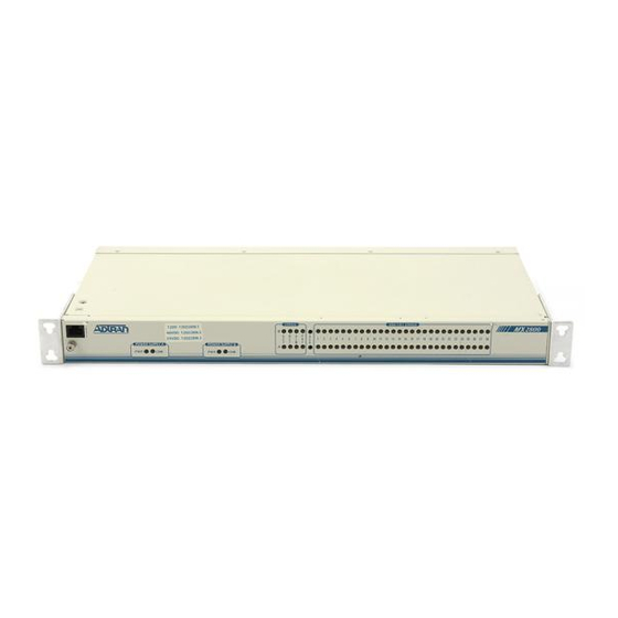
ADTRAN MX2800 M13 User Manual (200 pages)
ADTRAN Network Adapter User Manual MX2800 M13
Brand:
ADTRAN
| Category:
Multiplexer
| Size: 3.52 MB
Table of Contents
User Manual
1
Revision History
3
Fcc Radio Frequency Interference Statement
4
Table of Contents
7
Section 1
19
Product Overview
19
Introduction
19
Controller Card 1:1 Redundancy
20
T3 Overview
20
Snmp
20
Network Manager
20
Agent
21
Mib
21
6 Tl1
21
Telnet
21
Available Options
21
Breakout Panel (P/N 1200291L1)
21
E1 Patch Panel (P/N 1200291L5)
21
Battery Backup (P/N 4175043L2)
22
Fan Faceplate (P/N 1200466L1)
22
Figure 1-1. E1 Patch Panel
22
Figure 1-2. Installing Fan Faceplate
22
Section 2
23
Installation and Operation
23
Introduction
23
Receiving Inspection
23
ADTRAN Shipping Contents
23
Power up
24
Figure 2-1. DC Power Connector
25
Table 2-1. DC Connector Symbol Definitions
25
Rackmount Installation
26
Connecting the Breakout Panel
27
Connecting the E1 Patch Panel
27
Figure 2-2. the Breakout Panel
27
Rear Panel
28
Figure 2-3. MX2800 Rear View
28
Table 2-2. MX2800 Review View Identifiers
28
DSX-3 Interfaces
29
LAN Port
29
Modem Port
29
Noncritical and Critical Alarm Connectors
29
DSX-1/E1 Interfaces
30
Power Connection
30
Front Panel
30
Craft Port
30
Figure 2-4. MX2800 Front Panel
30
Establishing Terminal Connection
31
Main Menu
31
Navigating Within the Menus
32
Figure 2-5. Main Menu
32
Figure 2-6. Status Menu
33
Statistics
33
Status
33
Configuration
34
Figure 2-7. Statistics Menu
34
Figure 2-8. Configuration Menu
34
Figure 2-9. Loopback Menu
35
Loopbacks
35
Telnet Client
35
Figure 2-10.Telnet Client Menu
36
Logout
37
Privilege Level
37
ACO Buttons
37
LED Descriptions
37
Power Supply A/B Status Leds
37
Controller Cards Status Leds
37
Table 2-3. LED Conditions for Active Cards
38
T1/E1 Status Leds
39
Table 2-4. LED Conditions for Standby Cards
39
Table 2-5. T1/E1 LED Conditions
39
Replacing or Installing Cards
40
Figure 2-11.Replacing or Installing Cards
40
Section 3
41
Configuration
41
Introduction
41
Figure 3-1. Configuration Menu
41
Figure 3-2. Configuration Menu Tree
43
Network Interface
44
DS3 Configuration
44
Framing
44
Line Length
44
Figure 3-3. Network Configuration Menu
44
Timing
45
Remote Loopbacks
45
XCV Threshold
46
Protection Configuration
46
Active Controller
46
Network Protection
46
Maximum Switch Threshold
46
Min. Switching Period
46
Table 3-1. XCV Threshold Limits
46
Miscellaneous
47
Loopback Timeout
47
Shutdown Stand-By
47
DS2 Configuration
47
T1/E1 Interface
48
Figure 3-4. T1/E1 Interface Menu
48
T1/E1 State
49
Figure 3-5. T1/E1 State Menu
49
Set Multiple
49
T1/E1 Line Coding
50
Figure 3-6. Set Multiple Menu
50
T1/E1 Line Length
51
Figure 3-7. T1/E1 Line Coding Menu
51
T1/E1 Loopback Detection
52
Figure 3-8. T1/E1 Line Length Menu
52
T1/E1 Circuit Protection
53
Figure 3-9. Loopback Detection Menu
53
T1/E1 Line Identification
54
Figure 3-10.Circuit Protection Menu
54
XCV Threshold
55
Figure 3-11.Line Identification Menu
55
Table 3-2. XCV Threshold Limits for T1/E1
55
System Management
56
Figure 3-12.System Management Configuration Menu
56
Management Options
57
Forward IP to Remote DS3
57
Gateway IP Address
57
Local IP Address
57
Management Port
57
Modem Remote IP Address
57
Subnet Mask
57
Dialup Options
58
Ds3 Ip Mtu
58
DS3 Remote IP Address
58
Dial String
59
Figure 3-13.Dialup Options Menu
59
Idle Timeout
59
Initializing String
59
Maximum Redial Attempts
59
Primary and Secondary Phone Numbers
59
Answer on Ring
60
Connection Timeout
60
Dialout on Trap
60
Modem Baud Rate
60
Modem Mode
60
Pause between Calls
60
Hangup
61
Last Modem Response
61
SNMP Management Options
61
SNMP State
61
Trap Generation
61
Trap IP Addresses
61
Figure 3-14.Trap Generation Menu
62
Table 3-3. Trap Descriptions
62
Read Community Name
64
System Name
65
Trap Community Name
65
Write Community Name
65
Network Date/Time Option
65
Refresh Period
65
Server IP Address
65
State
65
DST Automatic Adjustment
66
Local Time Zone
66
System Security
66
Guest
66
Interface
66
User Account Management
66
Admin
67
RADIUS Authentication
67
RADIUS State
67
Test
67
Privilege Level
68
Server IP Address
68
Shared Secret Visibility
68
UDP Port
68
Maximum Retries
69
Response Timeout
69
Shared Secret
69
Table 3-4. Console Menu User Privileges
70
IP Hosts
71
IP Security
71
Terminal Time out
71
Date and Time
73
Miscellaneous
73
Alarm Relay Configuration
73
Figure 3-15. Alarm Relay Configuration Menu
74
Table 3-5. Types of Alarms in Alarm Relay Configuration
74
Equipment Identification
75
Facility ID
76
Figure 3-16.Equipment Identification Menu
76
Frame ID
76
Location ID
76
Unit Code
76
Unit ID
76
Equipment Codes
77
Host Facility
77
Host IP Address
77
Severity Level
77
Syslog Setup
77
Table 3-6. Syslog Severity Levels
77
Transmission
77
Auto Save
78
Craft Baud Rate
78
Utilities
78
Figure 3-17.System Utilities Menu
78
Loading Default Settings
79
Load Default Settings Other than System Management
79
Load System Management Default Settings
79
Table 3-7. Self-Test Results
79
Load All Default Settings
80
Updating Software
80
Update Via Xmodem
80
Configuration Transfer
82
Saving to a TFTP Server
82
Retrieving from a TFTP Server
83
Resetting the System
83
Save Configuration and Alarm Log
84
Figure 3-18.Indication of a Saved Configuration and Alarm Log
84
Section 4
85
Status
85
Introduction
85
DS3 State
85
Rx Framing
85
Figure 4-1. Status Menu
85
State
86
Alarm
86
Table 4-1. Network State Conditions
86
Table 4-2. Alarm Conditions
86
Remote
87
Table 4-3. Remote Alarm Conditions
87
Power Supply State
88
System State
88
Alarm
88
Table 4-4. Power Supply Conditions
88
Table 4-5. System State Alarm Types
88
Protection
89
Card Comm
89
Table 4-6. Controller Card States
89
Table 4-7. Protection Types
89
Acknowledge Alarms (ACO)
90
Table 4-8. DS2 States
90
Table 4-9. T1/E1 States
90
DS2 State
90
T1/E1 State
90
Section 5
91
Statistics
91
Introduction
91
Viewing Statistical Information
91
Figure 5-1. Statistics Menu
91
DS3 Statistics
92
24 Hour Alarm History
92
Figure 5-2. DS3 Statistics Menu
92
Table 5-1. Alarm Counts
92
Figure 5-3. DS3 Current 15 Minute Alarm Count Screen
93
Figure 5-4. DS3 24-Hour Alarm History Screen
94
Performance Parameters
94
Figure 5-5. DS3 Performance Parameters (Current 15 Minutes)
95
Figure 5-6. DS3 Performance Parameters (24 Hour History)
96
Figure 5-7. DS3 Performance Parameters (Totals)
97
Interval Starting at
97
C-Bit Code Violations (CCV)
98
C-Bit Errored Seconds (CES)
98
C-Bit Severely Errored Seconds (CSES)
98
Line Coding Violation (LCV)
98
Line Errored Seconds (LES)
98
P-Bit Coding Violations (PCV)
98
P-Bit Errored Seconds (PES)
98
P-Bit Severely Errored Seconds (PSES)
98
Severely Errored Framing Seconds (SEFS)
98
Unavailable Seconds (UAS)
98
Clear All Local DS3 Statistics/Refresh All Remote Statistics
99
Far End Block Error (FEBE)
99
DS2 Statistics
99
24-Hour Alarm History
99
Figure 5-8. DS2 Current 15 Minute Alarm Count Screen
99
Figure 5-9. DS2 RAI 24-Hour Alarm History
100
Figure 5-10.DS2 Performance Parameters (Current 15 Minutes)
101
Performance Parameters
101
Figure 5-11.DS2 PBERR 24-Hour Alarm History
102
T1/E1 Statistics
103
Figure 5-12.T1/E1 Port Local Statistics Menu
103
Protection Switch Statistics
104
Performance Parameters
104
Alarm Log
104
Figure 5-13.Protection Switch Statistics Menu
104
Figure 5-14.Alarm Log
105
Section 6
107
Loopbacks
107
Introduction
107
Figure 6-1. Loopback Menu
107
T1/E1 Loopbacks
108
Data Mode
108
Tributary
108
Figure 6-2. Loopback Control Menu
108
Analog Network
109
Digital Line/Net
109
Figure 6-3. Tributary Loopback Test
109
Figure 6-4. Analog Network Loopback
109
Figure 6-5. Digital Line/Network Loopback
109
Codec Line/Net
110
Remote Loopback
110
CSU Loopback
110
CSU Loopback W/Bert
110
Figure 6-6. Codec Loopback
110
Line BERT
111
Figure 6-7. Loopback Menu with BERT Selected
111
DS3 Loopbacks
112
Figure 6-8. DS3 Loopback Menu
112
Line Loopback
113
Digital Loopback
113
Figure 6-9. Line Loopback Test
113
Figure 6-10.Digital Loopback
113
Metallic Loopback
114
Remote Loopback
114
Remote All T1/E1
114
Figure 6-11.Metallic Loopback Test
114
DS2 Loopbacks
115
DS2 Network
115
Figure 6-12.DS2 Loopback Menu
115
Figure 6-13.DS2 Network Loopback Test
115
Section 7
117
Circuit and Network Redundancy
117
Introduction
117
Nonredundant Mode
117
Figure 7-1. Nonredundant Mode
117
Circuit Failure Recovery Mode
118
Figure 7-2. Circuit Failure Recovery Mode
118
Table 7-1. Configuration Requirements for Circuit Recovery
118
Circuit and Network Failure Recovery Mode
119
Figure 7-3. Circuit and Network Failure Recovery Mode
119
Section 8
121
Power Loss Recovery
121
Introduction
121
Nonredundant Power Mode
121
Figure 8-1. Nonredundant Power Mode
121
Power Supply Recovery Mode
122
Power Supply and Source Recovery Mode
122
Figure 8-2. Power Supply Failure Recovery Mode
122
Battery Backup Mode
123
Figure 8-3. Power Supply and Source Failure Recovery Mode
123
Figure 8-4. Battery Backup System
124
Section 9
125
Transaction Language 1 (TL1)
125
Introduction
125
Overview
125
Table 9-1. TL1 Account Privileges
126
TL1 Messages
127
TL1 Responses
127
Acknowledgment Messages
127
All Right
127
In Progress
127
Output Response Messages
128
Autonomous Messages
128
TL1 Commands
129
Table 9-2. TL1 Commands
130
TL1 Autonomous Messages
135
Table 9-3. MX2800 Alarm Events
136
Table 9-4. MX2800 Informational Events
140
TL1 Error Codes
141
TL1 Editing
141
Table 9-5. TL1 Error Codes
141
TL1 Editing Examples
142
Data Dictionaries
144
Table 9-6. TL1 Editing Data Dictionary for DS3
144
Table 9-7. TL1 Editing Data Dictionary for DS2
147
Table 9-8. TL1 Editing Data Dictionary for DS1
148
Table 9-9. TL1 Editing Data Dictionary for EQPT
151
Table 9-10. DS3 TL1 Loopback Commands
154
Table 9-11. DS2 TL1 Loopback Commands
154
TL1 Loopback Commands
154
Table 9-12. DS1 TL1 Loopback Commands
155
Acceptance Test Procedure
157
Appendix A
157
Introduction
157
Verifying the Installed Options
157
Configuring the System
158
Accessing the Craft Port
158
Provisioning the DS3 Port
158
DS3 Configuration
159
Protection Configuration
159
Miscellaneous
159
DS2 Configuration
159
Provisioning the DS1 Ports
160
Alarm Relay Configuration
161
Verifying the Data Integrity
161
DS1 Daisy-Chain to DS3 (Hard) Loopback
161
DS1 to DS3 Head-To-Head Test
162
DS1 to DS3 (Hard) Loopback
163
Verifying Alarm Notification
163
Critical Alarm Relay Test
163
Noncritical Alarm Relay Test
164
Verifying System Redundancy
164
Power Supply Redundancy
164
Single Power Supply Module / Dual Power Feeds
165
Dual Power Supply Modules / Dual Power Feeds
165
Controller Card Redundancy
166
Restoring Default Settings
166
Configuring the System for Traffic Readiness
167
Signing-Off the MX2800 ATP Checklist
168
Table A-1. MX2800 ATP Checklist
168
Appendix B
169
Pinouts
169
Table B-1. Craft Port Pin Assignments
169
Table B-2. LAN Port Pin Assignments
169
Table B-3. Modem Port Pin Assignment
170
Table B-4. Amphenol Pin Assignments
170
Appendix C
173
Specifications Summary
173
Introduction
173
Specifications and Features
173
• DSX-3 Network Interface
173
Interface(S
173
Clocking
174
Loopbacks
174
DS3 Network
174
DS2 Interfaces
174
DSX-1 Interfaces
174
Management
174
VT100 Terminal Interface
174
Integrated Modem Interface (4200290L1, 4200290L2, 4200290L3, 4200290L4
174
Snmp/Telnet
174
Alarms
175
Agency Approvals
175
Environment
175
Power
175
Physical
175
Appendix D
177
Acronyms/Abbreviations
177
Appendix E
183
Glossary
183
Appendix F
191
Warranty
191
Warranty and Customer Service
191
ADTRAN Sales
191
ADTRAN Technical Support
191
ADTRAN Repair/Caps
191
Repair and Return Address
191
Index
193
Advertisement
Advertisement
Related Products
ADTRAN MX2820
ADTRAN MX2800 STS-1
ADTRAN MX3216
ADTRAN TOTAL ACCESS MX2800
ADTRAN MX410
ADTRAN MX412
ADTRAN Mitel IP
ADTRAN SMART/RG MC60
ADTRAN Modem-16 Module
ADTRAN 1200287L1
ADTRAN Categories
Network Hardware
Network Router
Switch
Control Unit
Gateway
More ADTRAN Manuals
Login
Sign In
OR
Sign in with Facebook
Sign in with Google
Upload manual
Upload from disk
Upload from URL