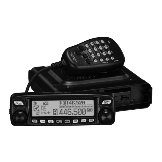
Yaesu FTM-100DR Operating Manual
144/430mhz
dual band transceiver
Hide thumbs
Also See for FTM-100DR:
- Operating manual (177 pages) ,
- Instruction manual (82 pages) ,
- Update instruction manual (13 pages)
Table of Contents
Advertisement
FTM-100DR
Operating Manual
144/430MHz
DUAL BAND TRANSCEIVER
C4FM/FM
Before Use
Installation and Connection
Basic Operations
Using the Memory
Using the GPS Function
Using the APRS Function
Using the GM Function
Using the WIRES-X Function
Convenient Functions
Functions to Use as Necessary
Customizing Menu Settings and
User Preferences
Using the Optional Accessories
(Bluetooth Devices/Voice Unit)
Scanning
Appendix
Advertisement
Table of Contents

Related Manuals for Yaesu FTM-100DR


Summary of Contents for Yaesu FTM-100DR
- Page 1 FTM-100DR Operating Manual 144/430MHz DUAL BAND TRANSCEIVER C4FM/FM Before Use Installation and Connection Basic Operations Using the Memory Scanning Using the GPS Function Using the APRS Function Using the GM Function Using the WIRES-X Function Convenient Functions Functions to Use as Necessary...
-
Page 2: Introduction
*Refer to the separate “GM Instruction Manual” Supports Yaesu WIRES-X Internet linking, enabling communication with remote partners via the Internet *Refer to the separate “WIRES-X Instruction Manual”... -
Page 3: Important Precautions For Mobile Transceiver Operation
Introduction Important precautions for mobile transceiver operation The use of protective tape or covering is recommended to protect the wiring and the power cord inside the vehicle. If precautions are not taken, the power cord may rub against sheet metal causing the wires beneath the cable sheathing to become exposed resulting in fire or equipment failure. -
Page 4: About Registered Trademarks And Copyrights
Other company and product names listed in this manual are trademarks and registered trademarks of their respective companies. Unauthorized reproduction or copying of a part or all of the copyrights owned by Yaesu Musen Co., Ltd. in any form whatsoever is strictly prohibited. -
Page 5: How To Read This Manual
Introduction How to read this manual In this manual, front panel operations are described as follows. Press ........Indicates that the key or switch is to be pressed briefly. Press for over one second ..Indicates that the key or switch is to be pressed for over one second. -
Page 6: Table Of Contents
Contents Introduction ..............2 Selecting communication mode ......39 Switching the modulation mode ......40 Features of this transceiver........2 Important precautions for mobile transceiver Communicating............41 operation ..............3 Transmitting ............41 About registered trademarks and copyrights ..4 Adjusting the transmit power ...... - Page 7 Contents Displaying your current location information ... 74 Copying data from the microSD memory card ............... 105 Displaying location information of the received station in digital mode ....... 74 Using the clone function........106 Saving location information Connecting an external device ....... 108 (GPS Log Function) ..........
- Page 8 Contents Notification of calls from partner stations Setup menu operations: 11 SD ....... 146 Copying the transceiver settings to a microSD (8 BELL RINGER) ..........131 Setting the squelch type separately for memory card (1 BACKUP) ......... 146 transmission and reception Initializing a microSD memory card (9 SQL EXPANSION) .........
-
Page 9: Before Use
Before Use Safety Precautions (make sure to read these) Make sure to read this manual in order to use this radio safely and correctly. Before using this product, note that the company shall not be liable for any damages suffered by the customer or third parties, or for any failures and faults that occur during the use or misuse of this product, unless otherwise provided for under the law. Type and meaning of the marks This symbol indicates the possibility of death or serious injury being inflicted on the user and the surrounding... - Page 10 Safety Precautions (make sure to read these) Do not operate the device when Do not touch any liquid leaking from flammable gas is generated. the liquid display with your bare Doing so may result in fire and hands. explosion. There is a risk of chemical burns occurring when the liquid comes Do not transmit in crowded places into contact with the skin or gets into in consideration of people who are the eyes. In this case, seek medical fitted with medical devices such as treatment immediately.
- Page 11 Safety Precautions (make sure to read these) Do not use the device when the Refrain from using headphones and power cord and connection cables earphones at a loud volume. are damaged, and when the DC Continuous exposure to loud volumes power connector cannot be plugged may result in hearing impairment. in tightly. Disconnect the power cord Please contact our company amateur and connection cables before customer support or the retail store incorporating items sold separately where you purchased the device as this and replacing the fuse.
- Page 12 Safety Precautions (make sure to read these) Keep out of the reach of small Do not place the device on an children. unsteady or sloping surface, or in If not, this may result in injuries to a location where there is a lot of children. vibration. The device may fall over or drop, Do not put heavy objects on top resulting in fire, injury and equipment of the power cord and connection failure. cables. This may damage the power cord and Do not stand on top of the product, connection cables, resulting in fire and and do not place heavy objects on...
-
Page 13: Checking The Supplied Items
Checking the supplied items Double-sided adhesive sheet DTMF microphone Bracket for main body Bracket for the MH-48A6JA MMB-36 controller Attachment screw set Controller cable DC power cable Spare fuse (15 A) (3 m) (with fuse attached) PC connection cable Stereo to monaural plug SCU-20 Operating Manual (this manual) Warranty Card... -
Page 14: Name And Function Of Each Component
Name and function of each component Front panel Front ③ ④ ① ⑤ ⑥ ② ⑦ ⑧ ⑨ ⑩ ⑪ ⑫ ⑬ ⑭ ➀ Power/LOCK key ( Pressing the key for over 2 seconds switches the power between ON and OFF. Briefly pressing the key while the transceiver is turned ON engages or releases the key lock. - Page 15 Name and function of each component • Allows you to select the desired item for setup, memory registration, group monitoring operation, etc. ➆ A/B DW key ( Briefly pressing each time switches the operating band between Band A and Band B. Pressing for over one second each time switches the dual watch function between ON and OFF.
-
Page 16: Rear
Name and function of each component Rear ③ ① ① ② ➀ CONTROL jack Connect the control cable into this jack to connect to the main body. ➁ Screw hole to attach the mounting bracket ➂ Firmware update switch Caution Keep the rubber cap on when not in use. Main body Front ④... -
Page 17: Rear
Name and function of each component Rear ① ⑤ ② ③ ④ ➀ ANT terminal Connect the antenna. ➁ 13.8V DC Connect the provided DC power supply cable (with fuse attached). ➂ EXT SP jack Connect the optional external speaker. ➃ DATA jack Connect a cable for remote operation or a cable for connecting to devices such as your computer interface unit and the external terminal unit. -
Page 18: Microphone (Mh-48A6Ja)
Name and function of each component Microphone (MH-48A6JA) [UP] Increases the frequency by one step. [DWN] Decreases the frequency by one step. [LOCK] Locks / unlocks the [UP] and [DWN] keys and [P1] to [P4] keys. [LAMP] Turns the lamp on the body of the microphone on/off. -
Page 19: Screen Display
Name and function of each component Screen display ③ ① ④ ② ⑤ ⑥ ⑦ ➀ Icon display Displays the Bluetooth, APRS, microSD memory card and GPS icons when each function is in use. ➁ Station location information display Displays the received station’s location information and your station location information. -
Page 20: Input Characters
Name and function of each component ● GPS INFO screen While a received station’s information is displayed, [Location display] briefly press the key to display the GPS INFO screen. May also display the compass and the signal level of each acquired satellite. □ indicates an un-acquired satellite and ■ indicates an acquired satellite. [Frequency display] Tip From [1 DISPLAY] →... -
Page 21: Installation And Connection
Installation and Connection Installing the transceiver Precautions on installation Note the following when installing the transceiver. Do not install the transceiver in a place where it would be exposed to direct sunlight, high temperatures, excessive humidity, dusty conditions, or extreme vibrations. ... -
Page 22: Installation Location When Used In A Mobile Unit
Installing the transceiver Installation location when used in a mobile unit ● Front panel To efficiently receive the GPS satellites, it is recommended that the transceiver should be installed on the dashboard or front side of the center console. See “Installing the front panel”... -
Page 23: About The Antenna
Installing the transceiver About the antenna The antenna is an extremely important part for both transmitting and receiving. The antenna type and its inherent characteristics determine whether the performance of the transceiver can be fully realized. As such, please note the following: ... - Page 24 Installing the transceiver ● Antenna installation when using a fixed station For use in an outdoor setting, there are omni-directional antennas and a variety of directional antennas. • Omni-directional antennas such as the GP (Ground Plane) antenna are suitable for communications with a local station or mobile stations in all directions.
-
Page 25: Installing The Main Body
Installing the transceiver Installing the main body Install the main body using the supplied MMB-36 bracket. Select the installation location. Caution Select a location where the transceiver can be securely attached. See “Installation location when used in a mobile unit” on page 22. Drill four 6 mm diameter holes in the location where the bracket is to be mounted, matching the positions of the bolting holes of the bracket. -
Page 26: Installing The Front Panel
Installing the transceiver Installing the front panel Install the front panel using the supplied bracket. Caution The bracket can be formed by hand to match the location where the front panel is installed. Be careful not to cause an injury when bending the bracket. Select the installation location. -
Page 27: Connecting The Transceiver
Connecting the transceiver Connecting the front panel to the main body Caution Make sure to turn the transceiver OFF before connecting. Connect the supplied control cable to the transceiver main body. Main body Push the control cable plug into the CONTROL Control jack on the front panel of the transceiver main cable... -
Page 28: Connecting The Power Supply
Connecting the power supply Connecting the car battery When using the transceiver as a mobile unit, connect the DC power supply cable to the car battery. Cautions z Use the transceiver in a car with a negative ground system where the minus (−) pole of the battery is connected to the car body. - Page 29 Connecting the power supply (2) Connecting the power supply cable Cautions z Do not use a DC power supply cable other than the one that is supplied or specified. z Do not place anything on the DC power supply cable or step on it. z Do not use the DC power supply cable with the fuse holder cut off.
-
Page 30: Connecting The External Power Supply Equipment
Connecting the power supply Connecting the external power supply equipment When using the transceiver as a fixed station, use an external power source. Cautions z Use an external power source capable of supplying DC 13.8 V, a current capacity of 20 A or more. z Make sure to switch OFF the power of the external power source before connecting. -
Page 31: Preparing A Microsd Memory Card
Use a new microSD memory card when data can no longer be written or erased. • Note that Yaesu shall not be liable for any damages suffered as a result of data loss or corruption in use of the microSD memory card. -
Page 32: Inserting A Microsd Memory Card
Preparing a microSD memory card Inserting a microSD memory card Press and hold for over 2 seconds to turn the transceiver OFF. Insert the microSD memory card into the microSD microSD card slot. card slot With the terminal side up, insert the card into the slot until it clicks. -
Page 33: Initializing Microsd Memory Cards
Preparing a microSD memory card Initializing microSD memory cards When using a new microSD memory card for the first time with the FTM-100DR, initialize it by following the procedure below. Caution Initializing deletes all the data recorded on the microSD memory card. Check the contents of the microSD memory card before initialization. -
Page 34: Basic Operations
Basic Operations Receiving Turning the power on Press and hold for over 2 seconds. The power switches on, and the display appears on the screen. <When using the same call sign for digital and APRS> <When using separate call signs for digital and APRS> The call sign for digital appears on the left and the call sign for APRS appears on the right. -
Page 35: Toggling The Operating Band
Receiving Press The display changes. The entered call sign appears at the bottom of the screen, and the screen switches to the frequency display screen. Toggling the operating band Normally, 2 operating bands appear on the top half and bottom half of the screen. The frequency and modulation mode may be changed only for the band on the top half of the screen, which is called “operating band”. -
Page 36: Adjusting The Squelch Level
Receiving Adjusting the squelch level Annoying noises can be eliminated when there is no signal present. The A-band and B-band squelch levels can be individually adjusted. Increasing the squelch level will be more effective in reducing noise; however setting the squelch level too high may block weak signals. -
Page 37: Tuning In To The Frequency
Receiving Tuning in to the frequency ● Using the DIAL Rotate the DIAL. Clockwise rotation tunes the frequency upwards, whereas counterclockwise rotation tunes the frequency downwards. ● Using the microphone Press [UP] and [DWN] briefly Pressing [UP] briefly, tunes the frequency upwards. Whereas pressing [DWN] briefly tunes the frequency in Number the downward direction. -
Page 38: Switching The Operation Mode
Receiving Rotate the DIAL to select [8 CONFIG], then press The menu list appears. Rotate the DIAL to select [7 FM AM STEP], then press Rotate the DIAL to select the desired frequency step. The frequency steps change in the following order: “AUTO” → “5.00 KHz” → “6.25 KHz” → “8.33 KHz”... -
Page 39: Selecting Communication Mode
The display switches to VFO mode and returns to the previous receive frequency. Selecting communication mode The FTM-100DR transceiver is equipped with the AMS (Automatic Mode Select) function which automatically selects from 4 modes of transmission corresponding to the signal being received. -
Page 40: Switching The Modulation Mode
Receiving Switching the modulation mode In analog mode, the modulation mode can be selected from “AUTO”, “MANUAL (FM)” and “MANUAL (AM)”. When shipped from the factory, the mode is set to “AUTO” where the most optimal modulation mode is automatically selected according to the frequency. Select the desired operating band. -
Page 41: Communicating
Communicating Transmitting Press and hold [PTT] on the microphone. In analog mode, both the upper and lower portions of the mode/status indicator light red. In digital mode, the upper portion of the mode/status indicator lights red and the lower portion of the mode/ PQRS WXYZ status indicator lights blue. -
Page 42: Adjusting The Transmit Power
Each time is pressed, the transmit power level changes in the following order: “HIGH” → “LOW” → “MID” Model HIGH FTM-100DR 50 W 20 W Adjusting the microphone sensitivity The sensitivity (gain) of the microphone can be adjusted. Press and hold for over one second. -
Page 43: Communicating In Fm Mode
To use the half deviation, select “1 ON” from [2 TX/RX] → [9 HALF DEVIATION] in the Setup menu. Communicating using the repeater The FTM-100DR includes the ARS (Automatic Repeater Shift) function which permits communication through repeaters automatically, by simply setting the receiver to the repeater frequency. -
Page 44: Changing The 100.0 Hz Ctcss Tone Squelch
Communicating Changing the 100.0 Hz CTCSS tone squelch To communicate with a repeater that uses a tone signal other than 100.0 Hz, change the CTCSS tone frequency using the setup menu. Tune the transceiver receiver frequency to the repeater frequency. Press for more than one second. Setup menu appears. Turn the DIAL to select [4 SIGNALING], and then press to display the menu list. -
Page 45: Other Settings
Other settings Changing the beep volume The volume of the key operation “beep sound” can be adjusted. Press and hold for over one second. The Setup menu appears. Rotate the DIAL to select [8 CONFIG], then press The menu list appears. Rotate the DIAL to select [8 BEEP], then press The volume setting value appears. -
Page 46: Locking The Dial And Keys
Press briefly again to unlock the DIAL and keys. “UNLOCK” will be displayed on the screen. Adjusting the date and time The FTM-100DR transceiver has a built-in clock. Set the time and date before using the radio. Also the clock is automatically set when signals are received from the GPS. Press and hold for over one second. The Setup menu appears. - Page 47 Other settings Press The “Month” display blinks. Rotate the DIAL to select the month Press appears on the upper side). The “Day” display blinks. Press to go back ( appears on the upper side). Rotate the DIAL to select the day. Press appears on the upper side).
-
Page 48: Adjusting The Display Brightness
Other settings Adjusting the display brightness The brightness and contrast of the display can be adjusted. Press and hold for over one second. The Setup menu appears. Rotate the DIAL to select [1 DISPLAY], then press The menu list appears. Rotate the DIAL to select [2 LCD BRIGHTNESS], then press The brightness level adjustment screen appears. -
Page 49: Restoring Defaults (All Reset)
Other settings Rotate the DIAL to select the desired contrast level. The contrast may be selected from the following 7 levels. “−3”, “−2”, “−1”, “0”, “+1”, “+2” and “+3” The default setting: 0 Press and hold for over one second. The selected contrast level is set and the display returns to the previous operating screen. - Page 50 Other settings Caution Performing the All Reset function clears all information registered to the memory channels. Be sure to write memory data down on paper or back up the data on a microSD memory card. For instructions on saving the data onto a backup microSD memory card, see “Setup menu operations: 11 SD” on page 146.
-
Page 51: Using The Memory
Using the Memory Frequently used frequencies and settings can be registered to the memory channels. The preset channels may be quickly recalled for convenient operation. The transceiver is also equipped with the following memory functions: · Skip memory channels to preclude reception during scanning ( page 67) ·... -
Page 52: Recalling Memories
Using the Memory Press and hold for over one second. The MEMORY WRITE screen appears. The frequency automatically appears on an empty memory channel. Tips • For details on how to assigning a nametag to a memory channel, see steps 4 to 12 in “Naming a memory channel”... -
Page 53: Recalling The Home Channel
Using the Memory Rotate the DIAL to select the desired memory channel. Press again to return to VFO mode. Unused memory channels are skipped. Recalling the home channel Press [P2] on the microphone. The home channel appears on the screen. Change the frequency by rotating the DIAL to return to VFO mode. -
Page 54: Changing The Frequency Of The Home Channel
Using the Memory Changing the frequency of the home channel The default frequency setting of the home channel can be changed. Switch to VFO mode. Rotate the DIAL to tune to the desired home channel frequency. Press and hold for over one second. The MEMORY WRITE screen appears. -
Page 55: Clearing Memories
Using the Memory Clearing memories Press and hold for over one second. The MEMORY WRITE screen appears. Press appears on the left side). Rotate the DIAL to select the memory channel from which memories are to be cleared. Press appears on the upper side). The erase confirmation screen appears. -
Page 56: Naming A Memory Channel
Using the Memory Press The display is returned to the previously viewed screen. Naming a memory channel Names (memory tags) such as call signs and the names of the broadcasting stations can be assigned to the memory channels and the home channel. Up to 8 of the following characters can be entered as a memory tag. - Page 57 Using the Memory Rotate the DIAL to select [Y], then press appears on the upper side). “Y” is entered, and the cursor moves to the right. To delete the letter, press appears on the upper side). Rotate the DIAL to select [M], then press appears on the upper side).
-
Page 58: Displaying The Memory Tag
Using the Memory Press The entered name appears on the right side of the screen. Press The entered name is registered to the memory channel and the display returns to the previous operating screen. The entered memory tag appears. Displaying the memory tag The frequency and name tag display format can be selected for each channel. -
Page 59: Split Memory
Using the Memory Split memory A separate transmit frequency may be registered to a memory channel to which a receive frequency has already been registered. In VFO mode, select the transmit frequency to be registered. Press and hold for over one second. The MEMORY WRITE screen appears. -
Page 60: Receiving Weather Broadcast Channels (Usa Version Only)
Using the Memory Receiving Weather Broadcast Channels (USA version only) This radio includes the preprogrammed VHF Weather Broadcast Station Memory Channel Bank, and can receive the broadcast or the weather alert by recalling or scanning a desired channel. The following channels are stored in the weather station memory bank of this radio. Channel Frequency Channel... -
Page 61: Listening The Weather Alert
Using the Memory Listening the weather alert In the event of extreme weather disturbances, such as storms and hurricanes, the NOAA (National Oceanic and Atmospheric Administration) sends a weather alert accompanied by a 1050 Hz tone and subsequent weather report on one of the NOAA weather channels. -
Page 62: Scanning
Scanning Searching for signals The FTM-100DR is equipped with a scanning function to search for memory channels and frequencies with active signals. Scanning can be performed using the following 5 methods: ● VFO scan Scan in VFO mode. ● All Memory Channel Scan Scan for all memory channels. -
Page 63: Selecting The Receiver Operation Performed After Scanning Stops
Searching for signals ● Canceling scanning Press [PTT] on the microphone to cancel scanning (this does not put the transceiver into transmit mode). Selecting the receiver operation performed after scanning stops Select one of the following 3 receiving operations to be performed after the scanning stops. -
Page 64: Memory Scan
Searching for signals Memory scan Frequencies registered to the memory channels can be scanned in the memory channel number order. Switch to memory mode. Press and hold [UP] or [DWN] on the microphone for over one second. Pressing [UP] scans the memory channels in an upward direction. -
Page 65: Selecting The Scanning Method
Searching for signals Selecting the scanning method To scan all memory channels or only the specified memory channels. Press and hold for over one second. The Setup menu appears. Rotate the DIAL to select [3 MEMORY], and then press The menu list appears. Rotate the DIAL to select [2 MEMORY SCAN TYPE], then press The setting options appear. -
Page 66: Specifying Memory Channels
Searching for signals Specifying memory channels Specific memory channels to be scanned may be selected using the Setup menu “2 MEMORY SCAN TYPE” set to “2 SELECT MEMORY”. Press and hold for over one second. The MEMORY WRITE screen appears. Press appears on the left side). -
Page 67: Scanning Only The Specified Memory Channels
Searching for signals Scanning only the specified memory channels Select the band to be scanned, and then switch to memory mode. Press and hold for over one second. The Setup menu appears. Rotate the DIAL to select [3 MEMORY], then press The menu list appears. -
Page 68: Scanning The Programmable Memories (Pms)
Searching for signals Press appears on the upper side). On the right side of the memory channel number display, “►” blinks. This indicates the “SKIP” state. The memory channels with this indicator are skipped during scanning. Tips • To unselect the memory channel, press twice. -
Page 69: Scanning The Programmable Memory Channels
Searching for signals Rotate the DIAL to tune to the desired upper scanning limit frequency. Tune in to the frequency to set for the upper limit (433.700 MHz). Press and hold for over one second. The MEMORY WRITE screen appears. Rotate the DIAL to select [UP1]. -
Page 70: Monitoring The Home Channel
Monitoring the home channel The FTM-100DR transceiver is equipped with a dual receive function (also known as dual watch (DW)) which periodically checks for signals on the home channel. When a signal is detected, the transceiver receives on the home channel. -
Page 71: Setting The Dual Receive Restart Setting
Monitoring the home channel Setting the dual receive restart setting Set how the transceiver dual receive mode operates after the signal on the home channel disappears by selecting one of the following 2 options: (1) Restarts dual receive operation in 3 seconds (AUTO). (2) Stops dual reception and continues receiving signals on the home channel (HOLD). -
Page 72: Using The Gps Function
Using the GPS Function The FT-100DM transceiver is equipped with an internal GPS reception unit to receive and display the location information at all times. The location information can be used for the following purposes: Save the location information of other stations and note whether or not they are within communication range. -
Page 73: Checking The Satellite Acquisition Status
Activating the GPS function About GPS positioning “Positioning” refers to the calculation of the GPS receiver position from the satellite orbit information, and the propagation time of the radio waves. For successful positioning, at least 3 satellites must be acquired. If positioning is unsuccessful, move the GPS receiver to an open space, as far from buildings as possible, where the view of the sky is unobstructed. -
Page 74: Displaying The Location Information
Activating the GPS function Displaying the location information Displaying your current location information On the normal screen, the current location information of your station is displayed on the left side of the frequency display. The screen displays the compass indicating the direction you are heading in and your station movement speed. -
Page 75: Checking The Route Using A Personal Computer
Activating the GPS function Rotate the DIAL to select [1 ON [xx sec]], then press The default setting: 2 OFF Rotate the DIAL to select the interval for saving the location information. “1 sec”, “2 sec”, “5 sec”, “10 sec”, “30 sec”, “60 sec” The default setting: 10 sec Press and hold for over one second. -
Page 76: Other Settings
Activating the GPS function Other settings ● Changing the geodetic reference system Set the geodetic reference in the Setup menu, [8 CONFIG] → [16 GPS DATUM]. You can select the geodetic reference system-positioning standard: “1 WGS-84”: Use the global geodetic reference system for positioning. This is the standard used all around the world. -
Page 77: Using The Aprs Function
When using the APRS function, station information such as the call sign and symbol of your own station need to be set in the APRS initial setup menus. For details, refer to the APRS Instruction Manual (download from Yaesu website). -
Page 78: Using The Gm Function
The GM function enables the display of all stations operating the GM function (up to 24 stations). For detailed information about the operation and functions of the GM mode, refer to the separate GM Function Instruction Manual (download from Yaesu website). - Page 79 How to use the GM function ● Displaying all the stations that are transmitting in the GM function Tune to the designated frequency on the operating band. Press The GM function activates and displays up to 24 stations transmitting in the GM mode on the same frequency, or stations running in DN mode, within the communication range.
-
Page 80: Using The Wires-X Function
When the transceiver is connected to WIRES-X, the call sings of other stations and rooms on the WIRES-X are displayed. To establish a WIRES-X node station, the WIRES-X connection kit “HRI-200” sold separately is required. For details, refer to the separate WIRES-X Instruction Manual (download from the Yaesu website). -
Page 81: Convenient Functions
Convenient Functions Communicating with specific stations Using the tone squelch function This radio is equipped with the CTCSS (Continuous Tone-coded Squelch System which allows audio to be heard only when receiving signals containing the same frequency tone as the tone that has been set in the tone squelch menu. By matching the tone frequency with the partner station in advance, a quiet standby monitoring is possible. -
Page 82: Using The Tone Squelch Function
Communicating with specific stations Using the tone squelch function Press and hold for over one second. The Setup menu appears. Rotate the DIAL to select [4 SIGNALING], then press The menu list appears. Rotate the DIAL to select [4 SQL TYPE], then press Rotate the DIAL to select [TONE SQL], then press for over one second. -
Page 83: Transmitting Tone Signals
Communicating with specific stations Transmitting tone signals Press and hold for over one second. The Setup menu appears. Rotate the DIAL to select [4 SIGNALING], then press The menu list appears. Rotate the DIAL to select [4 SQL TYPE], then press Rotate the DIAL to select [TONE ENC], then press for over one second. -
Page 84: Using The Digital Code Squelch Function
Communicating with specific stations Using the digital code squelch function This radio is equipped with a DCS (Digital Coded Squelch) function that allows audio to be heard only when signals containing the corresponding DCS code are received. By matching the DCS code with the partner stations beforehand, a quiet receive standby is possible. -
Page 85: Using The Dcs Function
Communicating with specific stations Using the DCS function Press and hold for over one second. The Setup menu appears. Rotate the DIAL to select [4 SIGNALING], then press The menu list appears. Rotate the DIAL to select [4 SQL TYPE], then press Rotate the DIAL to select [DCS], then press over one second. -
Page 86: Using The New Pager Function
Communicating with specific stations Using the new pager function Use the pager code consisting of 2 CTCSS tones to exchange communications with specified stations. Caution The new pager does not function in digital mode. To transmit signals utilizing the pager codes, use key to switch the communication mode to AMS (Auto Mode Select function) or analog (FM) mode. -
Page 87: Activating The New Pager Function
Communicating with specific stations Press and hold for over one second. Sets your station pager code and returns the display to the previously viewed screen. You can also return to the previous screen by pressing 3 times. Tips • Even if the first and second parts of the pager code are reversed, for example, [47 05] from [05 47], they are still recognized as the same code. -
Page 88: Calling A Specific Station
Communicating with specific stations Calling a specific station Press and hold for over one second. The Setup menu appears. Rotate the DIAL to select [4 SIGNALING], then press The menu list appears. Rotate the DIAL to select [6 PAGER CODE], then press The code setting screen appears. -
Page 89: Notification Of Incoming Calls From Partner Stations Using The Bell Function
Communicating with specific stations Notification of incoming calls from partner stations using the bell function While communicating using the tone squelch, DCS, or new pager function, a beep may be programmed to sound when a signal containing the corresponding code is received. Press and hold for over one second. -
Page 90: Other Squelch Functions
● User Programmed Reverse CTCSS Decoder In Setup menu, select [4 SIGNALING] →[4 SIGNALING] → [PR FREQ]. The user programmable Reverse CTCSS Decoder will mute the FTM-100DR receiver when a signal containing a matching CTCSS tone is received. ● DCS transmission From the Setup menu, select [4 SIGNALING] →... -
Page 91: Using The Dtmf Function
Using the DTMF function DTMF tones (Dual Tone Multi Frequencies) are the tones you hear when dialing from a telephone keypad. The FTM-100DR transceiver can transmit the DTMF codes by using the keys on the microphone or recalling registered numbers from memories. -
Page 92: Transmitting The Registered Dtmf Code
Using the DTMF function Press and hold for over one second. Sets the DTMF code and returns the display to the previously viewed screen. You can also return to the previous screen by pressing 3 times. Transmitting the registered DTMF code Press and hold for over one second. - Page 93 Using the DTMF function Rotate the DIAL to select “2 OFF”. Rotating the DIAL changes the function between “1 ON” and “2 OFF”. Press and hold for over one second. Returns the display to the previously viewed screen and displays on the top right side of the screen.
-
Page 94: Using The Timer Function
Using the timer function Using the APO function When the APO (Automatic Power-off) function is set to ON, the transceiver automatically turns off if no operation is performed for the designated time. A beep sounds about one minute before the transceiver turns off. For example, when connecting the transceiver to your car battery, the APO function prevents accidental draining of the battery. -
Page 95: Using The Tot Function
Using the timer function Using the TOT function By setting the TOT (Timeout Timer) function to ON, the transceiver automatically returns to receive after a transmission continues for the designated time. A beep sounds about 10 seconds before the transceiver returns to receive mode. The TOT prevents unintentional transmissions, interference to other communications and excessive battery power consumption. -
Page 96: Exchanging Messages Or Images
Exchanging messages or images While operating in digital mode, you can receive messages (text data) or images. Transmitted and received messages and images are all saved in the common list. Cautions z To receive a message or image, press to switch the communication mode to AMS (Automatic Mode Select Function) or digital mode in advance. -
Page 97: Deleting Messages Or Images
Exchanging messages or images Tips • displayed on the left side of the icon indicates that the image was successfully received. • Icons on the left side of the LOG list indicate the following. Creating and sending a new message Message received (unread) Message received (read) Message sent... -
Page 98: Deleting Data From The List
Exchanging messages or images Rotate the DIAL to select [OK?], then press Starts the deletion process. After completing deletion, the display returns to the data list screen. Rows move up by one. To cancel deletion, select [Cancel], then press Deleting data from the list From the data list, select the data you want to delete by rotating the DIAL. -
Page 99: Sending Massages Or Images
Exchanging messages or images Sending massages or images Send messages or images from the transceiver. Sent data can be viewed by all stations operating in digital mode on the same frequency. There are the following three ways for sending messages or images. (1) Creating and sending a new message (2) Replying to the sender of the downloaded message or image data (3) Forwarding the downloaded message or image data... -
Page 100: Using Routine Message
Exchanging messages or images Press appears on the upper side). Sends the message. To cancel transmission, press When message transmission completes, “Completed” appears and then the screen returns to the message list screen. The tag of the transmitted message is added to the top of the list. - Page 101 Exchanging messages or images To add letters to the message, input letters following steps 4 through 5 of “Creating and sending a new message” on page 99. ● Registering routine messages You can register up 10 routine messages using a maximum of 80 characters. Messages you registered can be selected and used in the same way as the 43 prepared routine messages.
-
Page 102: Replying To The Sender Of The Downloaded Message Or Image Data
Exchanging messages or images Replying to the sender of the downloaded message or image data Reply to the sender of the checked message or image data. Press and hold for over one second. Displays the “LOG SELECT” screen. Rotate the DIAL to select [GM MESSAGE] or PICT], then press When [GM... -
Page 103: Forwarding The Downloaded Message Or Image Data
Exchanging messages or images Forwarding the downloaded message or image data You can forward the checked message or image data. Press and hold for over one second. Displays the “LOG SELECT” screen. Rotate the DIAL to select [GM MESSAGE] or PICT], then press When [GM MESSAGE] is selected, the “GM... -
Page 104: Functions To Use As Necessary
Using a microSD memory card The data files saved in the FTM-100DR can be selected and copied to a microSD memory card which may then be used to transfer the data to other FTM-100DR transceivers. -
Page 105: Copying Data From The Microsd Memory Card
The display returns to the previously viewed operating screen. Copying data from the microSD memory card Insert the microSD card into the FTM-100DR transceiver from which data is to be copied, and then copy the data to the card. Remove the microSD card and insert it into the FTM-100DR transceiver to which the data is to be copied. -
Page 106: Using The Clone Function
Using the clone function, all data saved in the transceiver can be copied directly to other FTM-100 transceivers. Example: When using the clone function in two FTM-100DR transceivers Turn off the both transceivers. Connect the optional clone cable “CT-166” to the DATA jack on the rear side of the transceivers. - Page 107 DIAL to select [OK?], then press The data copy starts. When data copy completes, “Completed” appears. The FTM-100DR transceiver to which you copy the data restarts automatically. The screen displayed differs depending on the copied data. On the transceiver from which data is to be copied, press and hold for over one second.
-
Page 108: Connecting An External Device
(USB jack) Tips • Make sure to turn off the transceiver before connecting any cables. • When using the SCU-20 PC connection cable, install the designated driver on the computer. Download the driver and installation manual from the Yaesu website. -
Page 109: Transmitting Gps Location Information
• Make sure to turn off the transceiver before connecting any cables. • When using the SCU-20 PC connection cable, install the designated driver on the computer. Download the driver and installation manual from the Yaesu website. Transmitting GPS location information Turn on the transceiver. -
Page 110: Connecting External Device
To use this information, software operating with NMEA-0183 specified GGA and RMC sentence is required. Updating the transceiver firmware When a new firmware update for the transceiver is available, download the information from the Yaesu website to update the transceiver to the latest state. -
Page 111: Using The Transceiver For Packet Communications
Connecting an external device Using the transceiver for packet communications Connecting the transceiver to a TNC (Terminal Node Controller) enables packet communications through the transceiver. ● Preparation • TNC • Computer • Data cable* … Prepare a cable suitable for the connected device. *The following optional products are available. - Page 112 Connecting an external device • Data cable “CT-163” (optional) To the computer, etc. To the transceiver To the TCN, etc. ➀ PKD (packet data input) Dsub 9 pin ➀ – ➁ GND ➂ PSK (PTT) ➁ TXD (serial data output [transceiver → PC]) ➃...
- Page 113 Connecting an external device Rotate the DIAL to select [1 COM PORT SETTING], then press The detail settings screen appears. Rotate the DIAL to select [COM OUTPUT], then press Rotate the DIAL to select “PACKET”, then press “OFF” → “GPS OUT” → “PACKET” → “WAYPOINT” The default setting: OFF Rotate the DIAL to select [COM SPEED], then press Rotate the DIAL to select the desired communication speed, then press...
- Page 114 Connecting an external device Rotate the DIAL to select [3 DATA SQUELCH], then press The detail settings screen appears. Rotate the DIAL to select the desired squelch detection method for the packet communication, then press Select “1 TX:ON” or “2 TX:OFF”. The default setting: 1 TX:ON Press and hold for over one second.
-
Page 115: Other Connectable Devices
Connecting an external device Other connectable devices ● External speaker The optional high output, high fidelity, waterproof external speaker “MLS-200-M10” may be connected to the transceiver. Plug the external speaker into the EXT SP jack on the rear side of the transceiver. When an external speaker is connected to the EXT SP jack, the internal speaker does not output audio. -
Page 116: Customizing Menu Settings And User Preferences
Customizing Menu Settings and User Preferences From the Setup menu, the various functions of the transceiver may be customized according to your personal preferences. The functions are categorized into: display, transmission/reception, memory, device configuration, etc,. in the menu. It is easy to select the item to adjust from each menu list, and then input or select the desired setting. -
Page 117: Setup-Menu Listing
Setup-menu listing Selectable options Menu / Item Description (Options in bold are the default settings) 1 DISPLAY 1 SUB DISPLAY SELECT Sets the sub-display SUB BAND / TIME / VOLT content 2 LCD BRIGHTNESS Sets the screen MIN / 2 / 3 / 4 / 5 / 6 / MAX brightness 3 LCD CONTRAST Sets the screen contrast -3 / -2 / -1 / 0 / +1 / +2 / +3... - Page 118 Setup-menu listing Selectable options Menu / Item Description (Options in bold are the default settings) 7 PRG REV TONE Set the idle line squelch 300 Hz to 3000 Hz 1500 Hz 8 BELL RINGER Sets the number of OFF / 1 time / 3 times / 5 times / successive bell rings 8 times / CONTINUOUS 9 SQL EXPANSION...
- Page 119 WP FORMAT: NMEA6 / NMEA7 / NMEA8 / NMEA9 WP FILTER: ALL / MOBILE / FREQUENCY / OBJECT/ITEM / DIGIPEATER / VoIP / WEATHER / YAESU / CALL RINGER / RNG RINGER 2 DATA SPEED APRS: 1200 bps / 9600 bps Sets the APRS/DATA...
- Page 120 Setup-menu listing Selectable options Menu / Item Description (Options in bold are the default settings) 10 APRS 1 APRS COMPASS NORTH UP / HEADING UP Sets the APRS compass display 2 APRS DISTINATION Displays the model code APY∗∗∗ (cannot edit) 3 APRS FILTER Mic-E: ON / OFF Sets the filter function...
- Page 121 Sets the sort and filter SORT: TIME / CALLSIGN / DISTANCE FILTER: ALL / MOBILE / functions FREQUENCY / OBJECT/ITEM / DIGIPEATER / VoIP / WEATHER / YAESU / OTHER PACKET / CALL RINGER / RANGE RINGER / 1200 bps / 9600 bps...
- Page 122 Setup-menu listing Selectable options Menu / Item Description (Options in bold are the default settings) 25 VOICE ALERT Sets the voice alert V ALERT: NORMAL / TONE SQL / DCS / function RX-TSQL / RX-DCS TONE SQL: 67.0Hz to 254.1Hz 100.0Hz DCS: 023 to 754 023 * For details of the functions, refer to the APRS Instruction Manual.
-
Page 123: Setup Menu Operations: 1 Display
Setup menu operations: 1 DISPLAY Setting up the screen display (1 SUB DISPLAY SELECT) Choose the information be shown on the sub-display. Press and hold for over one second. The Setup menu appears. Rotate the DIAL to select [1 DISPLAY], then press Rotate the DIAL to select [1 SUB DISPLAY SELECT], then press The sub-display setting screen appears. -
Page 124: Switching The Gps Information (4 Gps Information)
Setup menu operations: 1 DISPLAY Switching the GPS information (4 GPS INFORMATION) You can set the information to display on the GPS INFO screen. Press and hold for over one second. The Setup menu appears. Rotate the DIAL to select [1 DISPLAY], then press Rotate the DIAL to select [4 GPS INFORMATION], then press Rotate the DIAL to select the GPS information to be... -
Page 125: Setup Menu Operations: 2 Tx/Rx
Setup menu operations: 2 TX/RX Setting the modulation mode (1 ANALOG MODE SELECT) You can select the modulation mode in analog mode. For details, see “Switching the modulation mode” on page 40. Setting the microphone sensitivity (2 MIC GAIN) You can set the microphone sensitivity (microphone gain). For details, see “Adjusting the microphone sensitivity”... -
Page 126: Setting The Squelch Type In Digital Mode (4 Digital Sql Type)
Setup menu operations: 2 TX/RX 1 AUTO: Automatically selects one of the 4 communication modes according to the received signal. 2 TX MANUAL: Automatically selects one of the 4 communication modes according to the received signal. Briefly pressing [PTT] on the microphone switches between digital mode and analog mode. -
Page 127: Setting The Digital Mode Squelch Code (5 Digital Sql Code)
Setup menu operations: 2 TX/RX Rotate the DIAL to select the desired squelch type. 1 OFF: Outputs sound whenever receiving digital signals from Yaesu transceivers. 2 CODE: Outputs sound only when receiving signals containing the SQL CODE corresponding to the code you set. -
Page 128: Setting The Time To Display The Partner Station Information In A Pop-Up Window (6 Digital Popup Time)
Sets the time and returns the display to the previously viewed screen. Setting your location information display (7 LOCATION SERVICE) For details of the functions, refer to the GM Function Instruction Manual (download from Yaesu website). -
Page 129: Sounding A Beep When A Partner Station Ends A Transmission (8 Standby Beep)
Setup menu operations: 2 TX/RX Sounding a beep when a partner station ends a transmission (8 STANDBY BEEP) In digital communication, the transceiver can inform you that the partner station completes a transmission by emitting a beep. Press and hold for over one second. -
Page 130: Using The Half Deviation Function (9 Half Deviation)
Setup menu operations: 2 TX/RX Using the half deviation function (9 HALF DEVIATION) You can lower the degree of modulation by half. Press and hold for over one second. The Setup menu appears. Rotate the DIAL to select [2 TX/RX], then press Rotate the DIAL to select [9 HALF DEVIATION], then press Rotate the DIAL to select the desired setting. -
Page 131: Setup Menu Operations: 4 Signaling
Setup menu operations: 4 SIGNALING Setting the tone frequency (1 TONE SQL FREQ) The tone frequency may be changed. For details, see “Selecting the tone frequency” on page 81. Setting the DCS code (2 DCS CODE) You can set the DCS code. For details, see “Selecting the DCS code”... -
Page 132: Setting The Squelch Type Separately For Transmission And Reception (9 Sql Expansion)
Setup menu operations: 4 SIGNALING Setting the squelch type separately for transmission and reception (9 SQL EXPANSION) You can set the squelch type separately for transmission and reception. Press and hold for over one second. The Setup menu appears. Rotate the DIAL to select [4 SIGNALING], then press Rotate the DIAL to select [9 SQL EXPANSION], then press Rotate the DIAL to select the desired setting. -
Page 133: Setup Menu Operations: 5 Scan
Setup menu operations: 5 SCAN Setting the signal reception method (1 DUAL WATCH STOP) While operating in the DW (Dual Watch) mode, the receive operation after detecting signals on the home channel may be changed. For details, see “Setting the dual receive restart setting” on page 71. Setting the scanning direction (2 SCAN DIRECTION) In the Setup menu, from [8 CONFIG] →... -
Page 134: Selecting The Receiver Operation Performed After Scanning Stops (3 Scan Resume)
The GM (group monitor) function enables the transceiver to automatically check whether the members on the same frequency are within communication range. For details, refer to the separate GM Function Instruction Manual (download from Yaesu website). Setup menu operations: 7 WIRES-X The WIRES-X is a communication system to broaden the amateur radio communication linking worldwide using the Internet. -
Page 135: Setup Menu Operations: 8 Config
Setup menu operations: 8 CONFIG Setting the date and time (1 DATE & TIME ADJUST) Set the date and time of the internal clock. For details, see “Adjusting the date and time” on page 46. Setting the time display format (2 TIME FORMAT) Select the internal clock time display: 24 hour display or 12 hour display. -
Page 136: Setting The Time Zone (3 Time Zone)
Setup menu operations: 8 CONFIG Setting the time zone (3 TIME ZONE) The internal clock can be synchronized with the Coordinated Universal Time via GPS. The time zone can be set at 0.5 hour increments within the range of ±14 hours. Press and hold for over one second. -
Page 137: Setting The Repeater Shift Direction (5 Repeater Shift)
Setup menu operations: 8 CONFIG Setting the repeater shift direction (5 REPEATER SHIFT) You can set the repeater shift direction. Press and hold for over one second. The Setup menu appears. Rotate the DIAL to select [8 CONFIG], then press Rotate the DIAL to select [5 REPEATER SHIFT], then press Rotate the DIAL to select the shift direction. -
Page 138: Setting The Frequency Step (7 Fm Am Step)
Setup menu operations: 8 CONFIG Setting the frequency step (7 FM AM STEP) Using the knobs (DIAL/VOL) and keys, you can change the frequency step. For details, see “Changing the frequency steps” on page 37. Setting the beep volume (8 BEEP) You can change the volume of the operation beep sound. - Page 139 Setup menu operations: 8 CONFIG Rotate the DIAL to select [10 MIC PROGRAM KEY], then press The microphone program key setting screen appears. Rotate the DIAL to select the program key ([P1] to [P4]) to which you want to assign a function, then press Rotate the DIAL to select the function you want to assign to the key, then press...
-
Page 140: Expanding The Reception Range (11 Rx Coverage)
Setup menu operations: 8 CONFIG Expanding the reception range (11 RX COVERAGE) You can expand the reception range to receive the aircraft band frequencies (108 to 137 MHz) and the information band frequencies (174 to 400 MHz, 480 to 999.99 MHz) as well. -
Page 141: Turning Off The Transceiver Automatically (13 Apo)
Setup menu operations: 8 CONFIG Turning off the transceiver automatically (13 APO) You can set the transceiver so that it automatically turns off if you do not perform any operation for the designated time. For details, see “Using the APO function” on page 94. Limiting the continuous transmission time (14 TOT) You can set the transceiver so that it automatically returns to receive mode after continuously transmitting for the designated time. -
Page 142: Setting The Interval For Saving The Gps Location Information (17 Gps Log)
Setup menu operations: 8 CONFIG Press and hold for over one second. Sets the GPS function geodetic reference system and returns the display to the previously viewed screen. Select “1 WGS-84” for the normal operation. Setting the interval for saving the GPS location information (17 GPS LOG) Set the interval for saving your location information onto the microSD memory card. -
Page 143: Setup Menu Operations: 9 Data
Setup menu operations: 9 DATA Setting the COM port (1 COM PORT SETTING) Set the communication speed and functions when using the DATA jack on the rear panel of the transceiver as the COM port. Press and hold for over one second. The Setup menu appears. - Page 144 This setting is required when “WAYPOINT” is selected in step 7. The setting switches as follows: “ALL” → “MOBILE” → “FREQUENCY” → “OBJECT/ITEM” → “DIGIPEATER” → “VoIP” → “WEATHER” → “YAESU” → “CALL RINGER” → “RNG RINGER” ALL: Outputs all the received beacons. MOBILE: Outputs only mobile station beacons.
-
Page 145: Setting The Aprs And Data Communication Speed (2 Data Speed)
VoIP: Outputs only beacons of VoIP stations such as WIRES. WEATHER: Outputs only beacons of the weather station. YAESU: Outputs only beacons of stations which are using Yaesu transceivers. CALL RINGER: Outputs only the information of call sign ringer stations which are set from [9 APRS RINGER (CALL)] in the APRS Setup menu. -
Page 146: Squelch Detection And Squelch Jack Output Settings (3 Data Squelch)
(1 BACKUP) Using a microSD memory card, the information registered to the memory channels, and the Setup menu settings may be recorded and transferred to other FTM-100DR transceivers. The settings saved on a microSD memory card may be imported to your transceiver. -
Page 147: Setup Menu Operations: 12 Option
Setup menu operations: 12 OPTION Setting the Bluetooth headset operations (1 Bluetooth) You can wirelessly receive and transmit voice messages using the Bluetooth headset by installing the Bluetooth unit onto the transceiver. For details, see “Setting the Bluetooth headset operations” on page 153. Setting the voice memory operations (2 VOICE MEMORY) By installing the voice guide unit onto the transceiver, you can record and play received audio, and also record and play audio from the microphone. -
Page 148: Recalling The Preset Setting (3 Recall Preset)
Setup menu operations: 13 RST/CLONE Press and hold for over one second. Returns the display to the previous operating screen. Recalling the preset setting (3 RECALL PRESET) You can recall the preset setting from the Setup menu. Press and hold for over one second. -
Page 149: Sorting The Memory Channels (5 Memory Ch Sort)
Resets the APRS setting and returns the screen to the previously viewed screen. Copying the saved data (7 CLONE) All the data saved on the transceiver directory may be copied (Cloned) to other FTM-100DR transceivers. For details, see “Using the clone function” on page 106. -
Page 150: Setup Menu Operations: 14 Callsign
Setup menu operations: 14 CALLSIGN Changing the call sign (1 MY CALLSIGN (DIGITAL)) The call sign ID registered to the transceiver may be changed using the set menu. Press and hold for over one second. The Setup menu appears. Rotate the DIAL to select [14 CALLSIGN], then press Press The currently registered call sign ID is shown. -
Page 151: Using The Optional Accessories (Bluetooth Devices/Voice Unit)
Bluetooth headset “BH-2A”. Activating the VOX (Voice Operated Xmit) function enables hands-free communications Bluetooth headsets other than the optional Yaesu headset may also be used, however not all the functions are guaranteed to work properly. Mounting the Bluetooth unit “BU-2”... - Page 152 Using the Bluetooth headset Gently lift up the top cover of the transceiver from the rear side. Caution Do not abruptly open the top cover. Doing so may break the cable connecting the internal speaker to the main board. Unplug the speaker cable from the socket on the main board to completely remove the top cover from the transceiver.
-
Page 153: Setting The Bluetooth Headset Operations
Using the Bluetooth headset Reconnect the speaker cable extending from the top cover to the socket on the main board. Attach covers using the 8 screws. Setting the Bluetooth headset operations The following settings may be changed for convenient wireless headset operation according to your personnel preferences. - Page 154 Using the Bluetooth headset Press Rotate the DIAL to select [2 BATTERY], then press Rotate the DIAL to select “NORMAL” or “SAVE”. “NORMAL”: Deactivates the battery saving function for the Bluetooth headset. “SAVE”: Activates the battery saving function for the Bluetooth headset. The default setting: NORMAL Press Rotate the DIAL to select [3 PTT MODE], then press...
-
Page 155: Identifying The Bluetooth Headset
When using the Bluetooth headset together with the transceiver for the first time, pairing is also required. The PIN code for the Yaesu Bluetooth headset BH-2A is “6111”. When using a Bluetooth headset manufactured by other companies, check the PIN code in the operating manual of the product. - Page 156 Using the Bluetooth headset The PIN code input screen appears. Tips • In the default setting, “6111” appears. • When using a headset other than BH-2A, input the devices 4-digit PIN code here. Rotate the DIAL to move the cursor to overwrite letters. •...
-
Page 157: Using The Bluetooth Headset
Using the Bluetooth headset Using the Bluetooth headset Once paired, the headset can be used simply by turning on the power. Tips • The communication distance between the headset and the transceiver is about 10 m or less. • The icon does not appear when the headset is too far from the transceiver and outside the sphere of communication. -
Page 158: Recording And Listening To Received Audio
Recording and listening to received audio You can record and playback the receiver audio using the optional voice guide unit “FVS-2”. By activating the announcement function, you can also hear the synthesized voice announcing the frequency of the operating band. Mounting the voice guide unit “FVS-2”... - Page 159 Recording and listening to received audio Unplug the speaker cable from the socket on the main board to completely remove the top cover from the transceiver. Caution When unplugging the speaker cable, do not pull the cable. Be sure to hold the connector part. Refer to the illustration on the right and carefully plug the FVS-2 into the connector.
-
Page 160: Using The Voice Memory
Recording and listening to received audio Using the voice memory The voice memory is a function for recording the received audio. The audio is saved onto the FVS-2 module that is mounted to the transceiver. The saved audio can be replayed and erased later on the transceiver. -
Page 161: Recording The Received Audio
Recording and listening to received audio Recording the received audio Press and hold for over one second. The menu appears in the bottom area of the screen. Press appears on the display). Recording begins. The recording time you set from [12 OPTION] → [2 VOICE MEMORY] in the Setup menu appears below [REC]. -
Page 162: Playing The Recorded Audio
Recording and listening to received audio Playing the recorded audio Press and hold for over one second. The menu appears in the bottom area of the screen. Press appears on the display) to select the desired track number. Tips • If there are two or more recordings, pressing each time switches the track number: “ALL”, “1”, “2”, …... -
Page 163: Activating The Frequency Voice Announcement
Recording and listening to received audio Rotate the DIAL to select [OK?], then press The recordings are erased. Caution This operation erases all the recorded audio. Even when there are 2 or more tracks, individual tracks cannot be erased. After erasing completes, “ALL” appears for [TRCK]. Press and hold for over one second. -
Page 164: Activating To The Frequency Announcement
Recording and listening to received audio Rotate the DIAL to select the desired language. Rotating the DIAL each time switches the language between “JAPANESE” and “ENGLISH”. The default setting: ENGLISH Press Rotate the DIAL to select [4 VOLUME], then press Rotate the DIAL to select the desired announcement volume level. -
Page 165: Appendix
Appendix Optional components ① ⑦ ② ④ ③ ⑩ ⑨ ⑧ ⑤ ⑪ ⑫ ⑬ ⑥ ➀ PC connection cable (SCU-20) ➇ Microphone extension kit (MEK-2) *Same as the one provided ➈ Microphone (MH-42C6J) ➁ Cloning cable (CT-166) ➉ Multifunctional DTMF microphone (MH-48A6JA) ➂... -
Page 166: Maintenance
Maintenance Care and maintenance Turn the power OFF before wiping away any dust and stains on the transceiver with a dry soft cloth. For stubborn stains, slightly moisten a soft cloth and wring it out before using it to wipe away the stains. Caution Never use washing detergents and organic solvents (thinner, benzene, etc.). -
Page 167: Troubleshooting
Troubleshooting Caution Check the following before requesting repair services. There is no power z Is the external power supply connected correctly? Connect the black wire to the negative (-) terminal and the red wire to the positive (+) terminal. z Is the voltage and current capacity of the external power supply sufficient? Check the voltage and current capacity of the external power supply. -
Page 168: About Internal Spurious Signals
Troubleshooting About internal spurious signals Certain frequency combinations of signals received simultaneously, may have an effect such as internal beats due to the high frequency of the internal oscillator. However, this is not a malfunction (refer to the calculation formulas below: n is any integer). Depending on the combination of the frequencies received simultaneously, there may also be fluctuations in the receiver sensitivity. -
Page 169: Specifications
Specifications ● General Frequency range : TX 144 - 146 MHz or 144 - 148 MHz 430 - 440 MHz or 430 - 450 MHz : RX 108 - 137 MHz (Air Band) 137 - 174 MHz (144 MHz HAM) 174 - 400 MHz (GEN1) 400 - 480 MHz (430 MHz HAM) 480 - 999.99 MHz (GEN2) Cellular Blocked (USA only) - Page 170 Specifications ● Receiver Circuit type : Double conversion super-heterodyne Intermediate frequencies : 1st : 47.25 MHz, 2nd :450 kHz Receiver Sensitivity 108 - 137 MHz (AM) 0.8μV typ for 10 dB SN 137 - 140 MHz (FM) 0.2μV for 12 dB SINAD 140 - 150MHz (FM) 0.2μV for 12 dB SINAD 150 - 174 MHz (FM)
-
Page 171: Index
Index Copying data to a microSD memory card ............104 About internal spurious signals ....168 Copying the radio data to another About the antenna ........23 transceiver ..........104 Activating the frequency voice Copying the saved data......149 announcement........163 Copying the transceiver settings to a Activating the new pager function .... - Page 172 Index Input characters........20 Recording the received audio....161 Inputting the call sign........ 34 registered DTMF code......92 Inserting a microSD memory card .... 32 Registering routine messages ....101 Installation location when used in Registering the DTMF code ..... 91, 131 a mobile unit ..........
- Page 173 Index Setting the digital mode squelch code..127 Specifying memory channels ....66 Setting the display brightness ....123 Split memory ..........59 Setting the display contrast ....123 Squelch detection and squelch jack Setting the DTMF code transmission output settings ........146 method ...........
- Page 174 1. Changes or modifications to this device not expressly approved by YAESU MUSEN could void the user’s authorization to operate this device. 2. This device complies with part 15 of the FCC Rules. Operation is subject to the following two conditions: (1) This device may not cause harmful interference, and (2) this device must accept any interference including received, interference that may cause undesired operation.
- Page 175 Copyright 2015 YAESU MUSEN CO., LTD. All rights reserved. YAESU MUSEN CO., LTD. No portion of this manual Tennozu Parkside Building may be reproduced 2-5-8 Higashi-Shinagawa, Shinagawa-ku, Tokyo without the permission of 140-0002 Japan YAESU MUSEN CO., LTD. YAESU USA Printed in Japan 6125 Phyllis Drive, Cypress, CA 90630, U.S.A.