Sony STR-DE675 Operating Instructions Manual
Hide thumbs
Also See for STR-DE675:
- Operating instructions manual (112 pages) ,
- Service manual (46 pages) ,
- Limited warranty (1 page)

Related Manuals for Sony STR-DE675


Summary of Contents for Sony STR-DE675
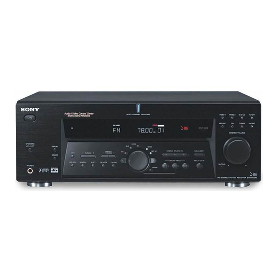
- Page 1 4-233-598-33(4) FM Stereo FM-AM Receiver Operating Instructions STR-DE675 2001 Sony Corporation...
- Page 2 And don’t place lighted candles on the concerning your receiver, please personnel only. receiver. consult your nearest Sony dealer. • To prevent fire or shock hazards, do not Do not install the place vases on the receiver. appliance in a confined...
-
Page 3: Table Of Contents
ABLE OF CONTENTS About This Manual The instructions in this manual is for model STR-DE675. Hooking Up the Components 4 Check your model number by looking at the lower right corner of the front panel. Unpacking 4 Antenna Hookups 5... -
Page 4: Hooking Up The Components
Hooking Up Unpacking Check that you received the following items with the receiver: Components • FM wire antenna (1) • AM loop antenna (1) • R6 (size-AA) batteries (2) • Remote Commander (remote) (1) This chapter describes how to connect Inserting batteries into the remote various audio and video components Insert R6 (size-AA) batteries with the + and –... -
Page 5: Antenna Hookups
Antenna Hookups AM loop antenna (supplied) FM wire antenna (supplied) DIGITAL OPTICAL ANTENNA DVD/LD TV/SAT MONITOR TAPE SPEAKERS IMPEDANCE USE 8 – 16Ω CTRL VIDEO IN VIDEO IN VIDEO IN VIDEO OUT VIDEO IN VIDEO OUT SURROUND CENTER FRONT TAPE Ω... -
Page 6: Audio Component Hookups
Audio Component Hookups Required cords Audio cords (not supplied) MD/TAPE deck When connecting a cord, be sure to match the color-coded pins to the appropriate jacks on the components. INPUT OUTPUT LINE LINE White (L) White (L) Red (R) Red (R) DIGITAL OPTICAL ANTENNA... -
Page 7: Video Component Hookups
Video Component Hookups Required cords Audio/video cords (not supplied) When connecting a cord, be sure to match the color-coded pins to the appropriate jacks on the components. Yellow (video) Yellow (video) White (L/audio) White (L/audio) TV or Satellite tuner DVD or LD player TV monitor Red (R/audio) Red (R/audio) -
Page 8: Digital Component Hookups
LD player with an RF OUT jack via an RF demodulator, Audio/video cords (not supplied) such as the Sony MOD-RF1 (not supplied). When connecting a cord, be sure to match the color-coded pins to the appropriate jacks on the components. - Page 9 Connect the digital output jacks of your MD or tape deck Required cords to the receiver’s digital input jack and connect the digital Optical digital cords (not supplied) input jacks of your MD or tape deck to the receiver’s digital output jack. These connections allow you to make Black Black digital recordings of a CDs played back through your...
-
Page 10: Multi Ch In Hookups
MULTI CH IN Hookups Although this receiver incorporates a multi channel Required cords decoder, it is also equipped with MULTI CH IN jacks. Audio cords (not supplied) These connections allow you to enjoy multichannel Two for the MULTI CH IN FRONT and SURROUND jacks software encoded in formats other than Dolby Digital and DTS. -
Page 11: Other Hookups
Other Hookups Required cords Audio cords (not supplied) When connecting a cord, be sure to match the color-coded pins to the appropriate jacks on the components. White (L) White (L) Red (R) Red (R) CONTROL A1 connecting cord (not supplied) Black Black AC power cord... - Page 12 (except models of area code CN) software. This may cause a malfunction. Caution • If you have a Sony CD changer with a Make sure that the total power consumption of the component(s) COMMAND MODE selector connected to the receiver ’s AC OUTLET(s) does not exceed the If your CD changer’s COMMAND MODE selector can...
-
Page 13: Hooking Up And Setting Up The Speaker System
Hooking Up SET UP Jog dial and Setting Up VIDEO 1 VIDEO 2 DVD/LD TV/SAT MULTI CHANNEL DECODING ? / 1 MD/TAPE TUNER INPUT MODE MASTER VOLUME the Speaker LEVEL DISPLAY SPEAKERS SURR SET UP – CINEMA STUDIO EX EQUALIZER PRESET NAME –... -
Page 14: Speaker System Hookup
Speaker System Hookup Required cords Speaker cords (not supplied) One for each front, surround, and center speaker Front speaker (R) Front speaker (L) (–) (–) Monaural audio cord (not supplied) One for an active sub woofer Black Black DIGITAL OPTICAL ANTENNA DVD/LD TV/SAT... - Page 15 To avoid short-circuiting the speakers Short-circuiting of the speakers may damage the receiver. To prevent this, make sure to take the following precautions when connecting the speakers. Make sure the stripped ends of each speaker cord does not touch another speaker terminal or the stripped end of another speaker cord.
-
Page 16: Performing Initial Setup Operations
Performing Initial Setup Operations Once you have made speaker connections and have Setting up the receiver turned on the power for the first time, clear the receiver’s Before you use your receiver for the first time, use the SET memory. After you have done this, set the speaker sizes, UP button to adjust settings to correspond to your system. -
Page 17: Multi Channel Surround Setup
The setting for Micro Satellite speaker (MICRO SP.) has been programmed to optimize the sound balance. If you use Sony’s Micro Satellite speakers, select MICRO SP. When you use Micro Satellite speaker and the speaker size is set to LARGE, you may not obtain the correct soundstage. - Page 18 Multi Channel Surround Setup p Front speaker size ( About speaker sizes (LARGE and SMALL) Internally, the LARGE and SMALL settings for each speaker Initial setting : LARGE determine whether or not the internal sound processor will cut • If you connect large speakers that will effectively the bass signal from that channel.
- Page 19 p Surround speaker height ( p Sub woofer selection Initial setting : HGT. LOW Initial setting : S. W. YES This parameter lets you specify the height of your • If you connect a sub woofer, select “S. W. YES”. surround speakers for proper implementation of the •...
- Page 20 Multi Channel Surround Setup About speaker distances Adjusting the speaker volume This receiver allows you to input the speaker position in terms of Use the remote while seated in your listening position to distance. However, it is not possible to set the center speaker adjust the volume of each speaker.
-
Page 21: Before You Use Your Receiver
Before You Use Your Receiver Notes Checking the connections • The front balance, surround balance, center level, and surround After connecting all of your components to the receiver, level are shown in the display during adjustment. do the following to verify that the connections were made •... - Page 22 Before You Use Your Receiver There’s no sound from a specific component. , Check that the component is connected correctly to audio input jacks for that component. , Check that the cord(s) used for the connection is (are) fully inserted into the jacks on both the receiver and the component.
-
Page 23: Location Of Parts And Basic Operations
Location of Front Panel Parts Descriptions Parts and Basic Operations This chapter provides information about the locations and functions of the buttons and controls on the front panel. It also explains basic operations. 1 ?/1 switch Press to turn the receiver on and off. 2 DISPLAY button Press repeatedly to change the information on the display window as follows:... - Page 24 Front Panel Parts Description VIDEO 1 VIDEO 2 DVD/LD TV/SAT MULTI CHANNEL DECODING ? / 1 MD/TAPE TUNER INPUT MODE MASTER VOLUME LEVEL DISPLAY SPEAKERS SURR SET UP – CINEMA STUDIO EX EQUALIZER PRESET NAME – – TUNING TUNING DIMMER SOUND FIELD MULTI CH IN MEMORY...
- Page 25 8 INPUT MODE button 0 MASTER VOLUME control Press to select the input mode for your digital After turning on the component you selected, rotate to components (DVD/LD, TV/SAT and MD/TAPE). adjust the volume. Each press switches the input mode of the currently selected component.
- Page 26 Front Panel Parts Description qj qk ql VIDEO 1 VIDEO 2 DVD/LD TV/SAT MULTI CHANNEL DECODING ? / 1 MD/TAPE TUNER INPUT MODE MASTER VOLUME LEVEL SPEAKERS DISPLAY SURR SET UP – CINEMA STUDIO EX EQUALIZER PRESET NAME – – TUNING TUNING DIMMER...
-
Page 27: Enjoying Surround Sound
The virtual sound modes contain compelling applications You can enjoy multi channel surround of the Sony Digital Cinema Sound digital signal when playing back software encoded processing technology. They shift the sound away from with Dolby Digital or DTS. -
Page 28: Selecting A Sound Field
Selecting a Sound Field SOUND FIELD LEVEL SURR You can enjoy surround sound simply by selecting one of VIDEO 1 VIDEO 2 DVD/LD TV/SAT MULTI CHANNEL DECODING ? / 1 the pre-programed sound fields according to the program MD/TAPE TUNER INPUT MODE MASTER VOLUME you want to listen to. - Page 29 Software with two channel audio signals, is decoded with Dolby Pro Logic to create surround effects. C. ST. EX A Reproduces the sound characteristics of Sony Pictures This is a standard mode, great for 1)2) (CINEMA STUDIO EX. A) Entertainment’s classic editing studio by using the 3D...
- Page 30 Selecting a Sound Field Sound field information Sound field Effect Notes V. M.DIMENS. Uses 3D sound imaging to create an array of virtual (VIRTUAL MULTI DIMENSION) surround speakers positioned higher than the listener from a single pair of actual surround speakers. This mode creates four sets of virtual speakers surround the SIDE** listener at approximately a 30°...
- Page 31 Use the buttons on the front panel to operate the following modes A.F.D. Automatically detects the type of audio signal being You can use this mode as a reference. Set AUTO FORMAT DECODING input (Dolby Digital, Dolby Pro Logic, or standard two the EQUALIZER to OFF while using this (Press the A.F.D.
-
Page 32: Understanding The Multi-Channel Surround Displays
Understanding the Multi-Channel Surround Displays DIGITAL PRO LOGIC MPEG STEREO MONO MEMORY SP. OFF COAX D.RANGE EQ L F E SL S SR 1 ; DIGITAL 8 COAX This indicator lights up when the receiver is decoding Lights up when the source signal is a digital signal signals recorded in the Dolby Digital format. - Page 33 Source sound displays The letters (L, C, R, etc.) indicate the source sound. The box around the letters varies to show how the receiver downmixes the source sound (based on the speakers settings). When using music sound modes such as SMALL HALL or JAZZ CLUB, the receiver adds reverberation based on the source sound.
-
Page 34: Customizing Sound Fields
Customizing Sound Fields Wall type By adjusting the surround parameters and the tone characteristics of the front speakers, you can customize Initial setting : WALL MID the sound fields to suit your particular listening situation. When sound is reflected off soft material, such as a curtain, the high frequency elements are reduced. - Page 35 *Sub woofer level Adjusting the level parameters Initial setting : S.W. 0 dB The LEVEL menu contains parameters that let you adjust Lets you adjust the level of the sub woofer. the balance and speaker volumes of each speaker. The •...
- Page 36 Customizing Sound Fields Dynamic range compressor ( D. RANGE Adjusting the equalizer Initial setting : COMP. OFF The EQ menu lets you adjust the equalization (low and Lets you compress the dynamic range of the sound track. high frequencies) of the front speakers. The equalizer This may be useful when you want to watch movies at settings are stored individually for each sound field.
- Page 37 Adjustable parameters for each sound field EFFECT WALL REVERB SCREEN FRONT SURR CENTER SURR SUB WOOFER LFE LEVEL TYPE TIME DEPTH BAL. BAL. LEVEL LEVEL LEVEL A.F.D. NORMAL SURROUND CINEMA STUDIO EX. A CINEMA STUDIO EX. B CINEMA STUDIO EX. C SEMI CINEMA STUDIO EX.
-
Page 38: Receiving Broadcasts
Receiving You can tune in stations on this receiver in the following ways: Broadcasts Direct Tuning You can enter a frequency of the station you want directly by using the numeric buttons on the remote (see page 40). Automatic Tuning This chapter describes how to receive If you don’t know the frequency of the station you want, you can let the receiver scan all available stations in your... - Page 39 PRESET TUNING +/– Brief descriptions of buttons used to receive broadcasts MEMORY TUNING +/– TUNER PRESET TUNING +/– : Press to scan all preset radio VIDEO 1 VIDEO 2 DVD/LD TV/SAT MULTI CHANNEL DECODING ? / 1 stations. MD/TAPE TUNER INPUT MODE MASTER VOLUME LEVEL...
-
Page 40: Direct Tuning
Direct Tuning Automatic Tuning For details on the buttons used in this section, see “Brief For details on the buttons used in this section, see “Brief descriptions of buttons used to receive broadcasts” on descriptions of buttons used to receive broadcasts” on page 39. -
Page 41: Preset Tuning
Preset Tuning For details on the buttons used in this section, see “Brief Tuning to preset stations descriptions of buttons used to receive broadcasts” on You can tune the preset stations either of the following page 39. two ways. Before tuning to preset stations, be sure to preset them by Scanning the preset stations performing steps on “Presetting radio stations”... -
Page 42: Other Operations
Other Cursor buttons NAME TUNER SET UP Operations VIDEO 1 VIDEO 2 DVD/LD TV/SAT MULTI CHANNEL DECODING ? / 1 MD/TAPE TUNER INPUT MODE MASTER VOLUME LEVEL DISPLAY SPEAKERS SURR SET UP – CINEMA STUDIO EX EQUALIZER PRESET NAME – TUNING –... -
Page 43: Naming Preset Stations And Program Sources
Naming Preset Stations and Recording Program Sources Your receiver makes it easy to record to and from the components connected to it. You don’t have to connect the You can enter a name (index name) of up to 8 characters playback and recording components directly to each for preset stations and program sources. -
Page 44: Using The Sleep Timer
Recording Using the Sleep Timer You can set the receiver to turn off automatically at a Recording on a video tape specified time. You can record from a TV, or an LD player using the receiver. You can also add audio from a variety of audio Press SLEEP on the remote while the power is on. -
Page 45: Adjustment Using The Set Up Button
The CONTROL A1 control system has been updated to the CONTROL A1 which is the standard system in the SONY 300 disc CD changer and other recent Sony components. Components with CONTROL A1 jacks are compatible with components with CONTROL A1 , and can be connected to each other. - Page 46 (i.e., 1 CD player, 1 MD Automatic function selection deck, 1 tape deck and 1 receiver). When you connect a CONTROL A1 compatible Sony (You may be able to connect more than one CD player or amplifier (or receiver) to other Sony components using MD deck, depending on the model.
-
Page 47: Additional Information
Also, see “Checking the connections” on page 21 to verify that the connections are correct. Should any problem persist, consult your nearest Sony dealer. There’s no sound or only a very low-level sound is heard. , Check that the speakers and components are connected securely. - Page 48 Troubleshooting No sound or only a very low-level sound is heard The surround effect cannot be obtained. from the surround speakers. , Make sure the sound field function is on (press , Make sure the sound field function is on (press SOUND FIELD MODE).
-
Page 49: Specifications
Specifications Inputs (Analog) Amplifier section FM tuner section MULTI CH IN, CD, POWER OUTPUT Tuning range 87.5 - 108.0 MHz DVD/LD, MD/TAPE, Models of area code SP, AU, E2/E3 TV/SAT, VIDEO 1, Rated Power Output at Stereo mode Antenna terminals VIDEO 2, AUX: (8 ohms at 1 kHz, THD 75 ohms, unbalanced... - Page 50 Specifications AC outlets 1 switched, total 100 W AM tuner section General maximum (except Tuning range Models of area code System Tuner section: models of area code AU, SP, CN PLL quartz-locked 531 - 1602 kHz (9 kHz digital synthesizer step) system 430 ×...
-
Page 51: Glossary
This is the generic name of the • Transition of sound from surround surround sound produced by digital speakers signal processing technology developed by Sony. Unlike previous Direct sound surround sound fields mainly directed at the reproduction of music, Level... -
Page 52: Settings Using Surr, Level, Eq, And Set Up Buttons
Settings Using SURR, LEVEL, EQ, and SET UP buttons You can make various settings using the LEVEL, SURR, EQ, SET UP buttons, jog dial, and cursor buttons. The table below shows each of the settings that these buttons can make. Press and light Press to select... -
Page 53: Remote Button Description
Remote Button Description You can use the remote to operate the components in your system. The tables below show the settings of each button. Remote Button Operations Function Remote Button Operations Function SLEEP Receiver Activates the sleep ENTER TV/VCR/SAT/ After selecting a channel, function and the Tape deck/ disc or track using the... - Page 54 CD player only). TITLE DVD player Displays DVD title. SUB CH +/–** Selects preset channels for the small picture. ** Only for Sony TVs with the picture-in-picture function. D. SKIP/CH/ Receiver Scans and selects preset PRESET +/– stations. Notes TV/VCR/SAT Selects preset channels.
- Page 55 TV/VTR VCD player DISC JUMP WIDE VIDEO SOUND FIELD MULTI CH/ * Sony VCRs are operated with a VTR 1, 2 or 3 setting. A.F.D. 2CH/OFF 2 CH DIRECT These correspond to Beta, 8mm and VHS respectively. – MODE MUTING...
-
Page 56: Index
AC power cord 11 adjustable parameters 37 antennas 5 customizing 34 audio components 6 pre-programmed 28 - 31 digital components 8 resetting 36 CONTROL A1 11, 45 selecting 28 speaker system 14 video components 7 http://www.world.sony.com/ Sony Corporation Printed in Malaysia...