Table of Contents
Advertisement
Advertisement
Table of Contents

Related Manuals for Motorola GP 68


Summary of Contents for Motorola GP 68
- Page 1 GP 68 Portable Radios User Manual...
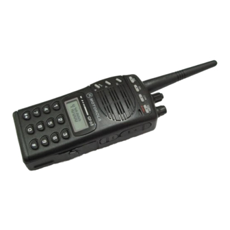
- Page 2 1. On / Off and Volume Knob 13. Backspace Button 2. Channel Selector Knob 14. Left Scroll Button 3. Antenna Connector 15. Right Scroll Button 4. Toggle Light / Enter Button 16. Accessory Connector 5. Monitor Button 17. SCI Port 6.
- Page 3 Copyright Information The Motorola products described in this manual may include copyrighted Motorola computer programs stored in semiconductor memories or other mediums. Laws in the United States and other countries pre- serve for Motorola certain exclusive rights for copy- righted computer programs, including the exclusive right to copy or reproduce in any form the copyrighted computer program.
-
Page 4: Table Of Contents
Contents Contents Introduction ........2 Packing Information......3 Knobs, Buttons, Connectors and Others . -
Page 5: Introduction
Introduction Introduction Congratulations on your purchase of a Motorola two- way radio. Your radio is a product of Motorola’s more than 50 years of experience as a world leader in the designing and manufacturing of communications equipment. This radio offers superior quality, superior performance, ultimate flexibility and years of reliable... -
Page 6: Packing Information
Packing Information Packing Information When you receive your packaged Motorola radio, inspect the shipping carton for any signs of damage. Next, remove and check the contents of the packing case to be sure that all items ordered have been included... -
Page 7: Knobs, Buttons, Connectors And Others
Knobs, Buttons, Connectors and Others Knobs, Buttons, Connectors and Others NOTE The numbers in brackets below refer to the loca- tions of the control buttons, knobs, etc. as shown in the illustration on the inside front cover. On / Off and Volume Knob (1) Turns the radio on and off and adjusts the volume level. - Page 8 Knobs, Buttons, Connectors and Others Signal Button (7) , Toggles between Carrier , Coded ( PL / DPL ), and Signalling Squelch modes. DTMF (Dual Tone Multiple Frequencies) digit ‘A’. Squelch Button (8) , Selects Carrier Squelch level. DTMF digit ‘B’. Low Power Button (9) , Toggles between high and low transmit power.
- Page 9 Knobs, Buttons, Connectors and Others Left Scroll Button (14) , Scrolls to the left when editing phone numbers and IDs. Right Scroll Button (15) , (non-keypad models) (keypad models) Scrolls to the right when editing phone numbers and IDs. If held on power-up, radio enters into Special Pro- gramming mode.
- Page 10 Knobs, Buttons, Connectors and Others Enable / Disable PTT ID Key (20) , Enables / disables PTT ID (long press). DTMF digit ‘#’. Pressing this key after sends the programmed phone deaccess code. Pressing this key immediately following inserts a pause. Lock / Unlock Key (21) , Locks / unlocks the keypad (long press).
-
Page 11: Getting Started
Getting Started Getting Started Attaching and Removing the Antenna Attaching Fasten the antenna to the radio by placing the threaded end of the antenna into the Antenna Con- nector (3). Rotate the antenna clockwise until tight. Removing • Turn the antenna in an anti-clockwise direction until it disengages from the radio. - Page 12 Getting Started Removing Release the Battery Latches (23). Slide the Battery Pack (22) away from the radio. Charging NiCd Battery Pack Before using your radio with a rechargeable (NiCd) battery, you must charge the battery. WARNING DO NOT attempt to charge your radio if you are using alkaline batteries.
- Page 13 Getting Started Charging your Battery for the FIRST time New batteries are supplied in a totally uncharged state. To ensure maximum battery performance, a new battery MUST be FULLY charged. Refer to the fol- lowing table for guidelines. Table 1: Length of time required to fully charge a new battery Standard High...
- Page 14 Getting Started Table 2: Length of time required to fully recharge a used battery Standard High Capacity Capacity NiCd Battery NiCd Battery Pack Pack Wall Charger (with/ 10 hours 20 hours without Wall Charger Base) Standard Desktop 10 hours 10 hours Charger Quick Charge 3 hours...
- Page 15 Getting Started If not using the Charger Base: Lift the dust cover covering the Accessory Connec- tor (16). Insert one end of the Wall Charger into the lower port of the Accessory Connector (16), and the other into an electrical outlet. If using the Charger Base: Insert the radio / battery into the charging docket.
- Page 16 Getting Started Insert the radio / battery into the charging docket. If using the Quick Charge Desktop Charger: Press the Quick Charge button. Refer to Table 1 and 2 on pages 10 and 11 for an estimation of the duration involved for charging the battery pack.
-
Page 17: Basic Operations
Basic Operations Basic Operations Turning the Radio On • Rotate the On / Off and Volume Knob (1) clock- wise to turn the radio on. Turning the Radio Off • Rotate the On / Off and Volume Knob (1) anti- clockwise until a click is heard to turn the radio off. -
Page 18: High / Low Power Output
Basic Operations NOTE Empty memory / unprogrammed channels are not displayed. High / Low Power Output • Press to toggle between high and low power output levels. NOTE The indicator LOW lights up on the LCD Screen (18) when the radio is operating in low power mode. NOTE High power mode can improve the clarity of voice activity in areas where signals are weak while low... -
Page 19: Receiving
Basic Operations NOTE Unless disabled (‘dot’ indicator flashes on the LCD Screen (18) ), PTT ID tones are heard as they are being transmitted (see “ PTT ID” on page 17). You can start your conversation when the tones end. NOTE The ‘TX’... -
Page 20: Additional Operations
Additional Operations Additional Operations Display Backlight • Press the Toggle Light / Enter Button (4) to turn on / off the backlight. NOTE To conserve power, the backlight is programmed to automatically turn off after 5 seconds. NOTE Pressing either the Push-To-Talk (PTT) Button (6) or the Monitor Button (5) has no effect on the back- light. -
Page 21: Locking / Unlocking The Radio's Function
Additional Operations Locking / Unlocking the Radio’s Function Locking the radio will disable all buttons except the Toggle Light / Enter Button (4) , Monitor But- ton (5) , Push-To-Talk (PTT) Button (6) and Pressing a locked button will result being shown on the LCD Screen (18) .To lock / unlock the radio:... - Page 22 Additional Operations NOTE To perform Signalling Squelch (SelCall ) operation, the radio must be equipped with an optional DTMF Decode board . To temporarily override the default receive squelch mode for the channel: • Press to change between Carrier (CSQ), Coded (PL / DPL) and Signalling (SelCall) squelch modes.
-
Page 23: Setting Squelch Level
Additional Operations Setting Squelch Level An open (low) squelch level sets the threshold for the receiving signal strength to be low. This means that the radio would receive a great variety of signals, both weak and strong. A tighter (higher) squelch level raises the threshold, thus filtering weak signals and only accepting the stronger ones. -
Page 24: Scan Operations
Scan Operations Scan Operations Scan operation tells the radio to monitor a list of pre- programmed channels (see “Editing the Channel Scan List” on page 31). When there are some activi- ties at a particular channel, the radio stops scanning and changes to that channel. - Page 25 Scan Operations NOTE While scanning is in progress, if the Push-To-Talk (PTT) Button (6) is pressed, the radio would trans- mit on the Home Channel . However, if the radio has stopped scanning and is receiving signals from a particular channel, all transmit and receive activity would be performed on that channel.
-
Page 26: Dtmf Telephone Interconnect
DTMF Telephone Interconnect DTMF Telephone Interconnect Dual Tone Multiple Frequency (DTMF) tones are encoded by the radio to dial into ( access ) the landline telephone network and return ( deaccess) to conventional radio operation. Once the telephone network has been accessed, phone numbers can be dialled either manually or from memory. - Page 27 DTMF Telephone Interconnect NOTE If you press a phone number location which has not been programmed, the radio will sound an Invalid Button Press tone and no further action is taken. To hang up: Press and hold the Push-To-Talk (PTT) Button (6). Manually dial the deaccess code or press then to send the preprogrammed deaccess...
- Page 28 DTMF Telephone Interconnect Storing a Phone Number A maximum of 9 telephone numbers (up to 12 digits each) can be stored into the radio memory. Each phone number is stored and recalled via a unique number on the keypad in the range of 1 to 9. The fol- lowing procedure can also be used to store the access / deaccess codes (up to 8 digits each): Press and hold...
- Page 29 DTMF Telephone Interconnect NOTE If you make a mistake, press to scroll the cur- sor to the left and erase the incorrect entry. To view a numeric sequence of more than 6 digits, press to scroll the cursor to the left or right. NOTE All undefined digits are represented by underscores on the LCD Screen (18) .
-
Page 30: Voice Selective Call (Optional)
Voice Selective Call (Optional) Voice Selective Call (Optional) To support Voice Selective Call (SelCall) operation, the radio must be equipped with an optional DTMF Decode board. NOTE For more information about the availability of this option, contact your dealer. If your radio is equipped with the Voice Selective Call option, your radio can be called individually by another user, or as part of a small group. - Page 31 Voice Selective Call (Optional) When the radio decodes a Voice Selective Call, it enters the carrier squelch mode for a period of time. If there is no receive activity, the radio resumes the selected squelch mode and the LCD Screen (18) reverts to the appropriate receive mode display.
-
Page 32: Special Programming Mode (Spm)
Special Programming Mode (SPM) Special Programming Mode (SPM) The Special Programming mode (SPM) allows you to edit all user-modifiable parameters within your radio, such as the Channel Scan list , Phone Access / Deac- cess codes , and Alert Tone Settings . Certain parame- ters (such as the Selective Call Tone Status ) are only accessible with the installation of an option board. -
Page 33: Spm Browse Menu
Special Programming Mode (SPM) SPM Browse Menu (Anti-Clockwise Rotation) “Beep” (Clockwise Rotation) FIRST ITEM Edit Channel Scan List Set Accessory Option * Edit Phone Access Code * Edit Phone Deaccess Code Set Battery Type † Edit Time Out Timer Set Battery Saver Status §... - Page 34 Special Programming Mode (SPM) Editing SPM Parameters Editing the Channel Scan List In SPM, rotate the Channel Selector Knob (2) to select the Edit Channel Scan List ( ) menu item. ) to scroll through the channels (01 to 20). NOTE The channel scan list does not wrap around to the opposite end of the list.
- Page 35 Special Programming Mode (SPM) NOTE The LCD Screen (18) displays the current access / deaccess code. For a code which exceeds the 6- digit display length, the rightmost digit flashes to indicate that more digits exist on the right. Enter the new access / deaccess code (up to 8 dig- its) using any of the numeric keys, A, B, C, D,* and NOTE The LCD Screen (18) shows the new digits as they...
- Page 36 Special Programming Mode (SPM) the edit mode time-out (after 5 seconds of inactiv- ity). Editing the Time-Out Timer Duration In SPM, rotate the Channel Selector Knob (2) to the Edit Time Out Timer ( xxx) menu. NOTE xxx represents one of , .., .
- Page 37 Special Programming Mode (SPM) NOTE Setting the Alert Tone Volume to off disables all tones regardless of the setting of this parameter (see “Setting the Alert Tone Volume” on page 35). In SPM, rotate the Channel Selector Knob (2) to the Set SelCall Tone Status ( menu.
- Page 38 Special Programming Mode (SPM) Setting the Alert Tone Volume In SPM, rotate the Channel Selector Knob (2) to the Alert Tone Volume ( ) menu. ) to toggle between On and Off. NOTE When is chosen, the alert tone volume fol- lows the volume control setting (see “Adjusting the Volume”...
- Page 39 Special Programming Mode (SPM) To exit this menu, select another menu item by turning the Channel Selector Knob (2). NOTE The Battery Saver feature is not active during chan- nel scanning, when the Push-To-Talk (PTT) Button (6) is pressed, or when the radio is receiving a sig- nal.
- Page 40 Special Programming Mode (SPM) In SPM, rotate the Channel Selector Knob (2) to the Set Accessory Option ( - Autosense or - Speaker Microphone Only or Headset Only) menu . Use the ) to scroll through the three options. CAUTION The new setting is stored immediately.
-
Page 41: Lcd Segments And Indicators
LCD Segments and Indicators LCD Segments and Indicators LOW CTCSS BATT SCAN SAVE SIGNAL Indicators TX - Lights up when radio is transmitting. LOW - Lights up when radio is in low transmit power mode. CTCSS - Lights up continuously for Coded Squelch mode;... -
Page 42: Alert Tone Indicators
Alert Tone Indicators Alert Tone Indicators Successful Power-Up A short, high-pitched tone when the radio is turned on indicates that the radio has passed its power-up self- test and is ready for use. Unsuccessful Power-Up A short, low-pitched tone immediately following the Successful Power-Up tone indicates that the radio has detected an error and has failed to power-up properly. - Page 43 Alert Tone Indicators Individual Selective Call Decode Two short “ringing” tones indicate that an Individual Selective Call has been decoded by the radio. The radio automatically sends an Acknowledgment ID . Acknowledgment ID Decode A short “ringing” tone indicates that a correct Acknowl- edgment ID has been decoded by the radio.
-
Page 44: Radio To Radio Cloning
Radio to Radio Cloning Radio to Radio Cloning Cloning duplicates the contents of one radio (the mas- ter radio) into another (the slave radio). Only current radio configuration, channels and phone numbers are copied from one radio to another. Tuning and align- ment information are not affected by cloning. - Page 45 Radio to Radio Cloning Turn on the slave radio. Press and hold before turning on the master radio. NOTE The master radio displays on the LCD Screen (18) if cloning can proceed, otherwise an error message will be shown. NOTE The slave radio displays while it is being pro- grammed.
-
Page 46: Information For Safe, Efficient Operation
Those guidelines are consistent with the safety stan- dards* previously set by both U.S. and international standards bodies. The design of your Motorola two- way radio complies with the FCC guidelines and these standards. *American National Standards Institute (C95.1 - 1992);... - Page 47 Information For Safe, Efficient Operation Electromagnetic Interference/compatibility Nearly every electronic device is susceptible to elec- tromagnetic interference (EMI) inadequately shielded, designed or otherwise configured for electro- magnetic compatibility. • Turn your radio OFF in any facilities where posted notices instruct you to do so. Hospitals or health care facilities may be using equipment that could be sensitive to external RF energy.
- Page 48 Information For Safe, Efficient Operation would normally be advised to turn off your vehicle engine. WARNING • Turn your radio OFF when in any area with a potentially explosive atmosphere, unless it is a type especially qualified for such use (for exam- ple, FMRC Approved).
-
Page 49: Recycling / Disposal Of Nicd Batteries
Motorola fully endorses and encourages the recycling of NiCd batteries. The following is a list of recycling facilities around the world, where you can ship your... - Page 50 EPA for specific legal require- ments and for recycling options in your area. Motorola, as a responsible corporate citizen, has always been concerned with the protection of the envi- ronment. Please feel free to call our toll-free number,1-...
-
Page 51: Licensing & Service Information
If your radio fails to operate or any operational difficulties arise, contact your local Motorola dealer. Proper repair and maintenance procedures assure efficient operation and long life for this radio. -
Page 52: Troubleshooting
Troubleshooting Troubleshooting Radio is dead. Possible Problem (1): Batteries may be dead (alkaline) or not properly charged (NiCd). Solution :If the display does not light, or the ‘BATT’ indicator flashes on and off, you should replace the alkaline batteries, or if you are using NiCd batteries, recharge them. - Page 53 Troubleshooting Possible Problem (3): The battery life is based on a duty cycle where the radio is transmitting 5%, receiving 5%, and in standby mode 90% of the time. Usage that differs from this will change the typical battery life expect- ancy accordingly.
- Page 54 Troubleshooting Radio will not talk to other radios in system. Possible Problem (1): Radios may be on different fre- quencies, having different Coded Squelch Codes. Solution :Verify that frequencies and Coded Squelch Codes are the same for all radios in your talk group. Hearing other conversations or noise on your radio.
- Page 55 Troubleshooting Possible Problem (2): Operating the radio while it is close to your body (i.e. in a pocket or on a belt) and while you are using audio acces- sories decreases its range because of the shielding effect of your body. Solution :The higher the radio is held, the better the talk range.
- Page 56 Possible Problem (1): The radio may need to be repaired. Solution :If the unit is still under warranty, return it to the place of purchase for repairs, or contact your nearest Motorola dealer listed in your local yellow pages.
-
Page 57: Accessories
Accessories Accessories NOTE Please note that all accessories may not be availa- ble in all markets. Contact your dealer for more information. Battery & Charging Accessories: 2580162R02 220V Transformer (must be ordered with ETN4609) ETN4609 GP68 3 Hour Charger Pocket (has to be ordered in conjunction with transformer... - Page 58 Accessories HMN9787 Light Weight Headset with Swivel Boom Microphone (w/out VOX) Carrying Cases & Accessories: HLN8240 Replacement 2 1/2” Belt Clip (Black) HLN8255 Spring Action Belt Clip 3” (Black) HLN9985 Waterproof Bag Radio to Radio Cloning Accessory: PMLN4068 Radio to Radio cloning cable PMLN4074 Programming cable...