Vertex Standard VX-820 Series Operation Manual
Hide thumbs
Also See for VX-820 Series:
- Service manual (66 pages) ,
- Operating manual (24 pages) ,
- Product manual (28 pages)

Related Manuals for Vertex Standard VX-820 Series


Summary of Contents for Vertex Standard VX-820 Series
- Page 1 VX-820 S erieS perating anual Vertex Standard LMR, Inc. 16-K -lCD V erSiOn erSiOn erSiOn...
-
Page 2: Table Of Contents
OntentS Important Note ............2 Operation ..............18 Intrinsic Safety (IS) Information ......3 Preliminary Steps ..........18 Warning! FCC RF Exposure Requirements ..4 Operation Quick Start ........18 Warning! IC RSS General Requirements ....4 Automatic Time-Out Timer ....... 20 Controls &... - Page 3 You now have at your fingertips a valuable communications tool-a Vertex Standard two-way radio! Rugged, reli- able and easy to use, your Vertex Standard radio will keep you in constant touch with your colleagues for years to come, with negligible maintenance down-time. Please take a few minutes to read this manual carefully. The in- formation presented here will allow you to derive maximum performance from your radio, in case questions arise later on.
-
Page 4: Important Note
There are no owner-serviceable parts inside the radio. All service jobs must be referred to an authorized Vertex Standard Service Representative. Consult your Authorized Vertex Standard Dealer for installation of optional accessories. r In order to maintain the specified water integrity performance, periodic maintenance is recommended. - Page 5 ( is ) i ntrinsiC afety nformation IS versions of the VX-820, equipped with any of the following optional units, meets the requirements of ANSI/UL 913 5th Edition for Class I, Division 1, Groups C-D; Class II, Groups E-G; and Class III for hazardous locations. Battery Packs: FNB-V92LIIS Speaker Microphone:...
- Page 6 ! fCC rf e arning xposure equirements This Radio has been tested and complies with the Federal Communications Commission (FCC) RF exposure lim- its for Occupational Use/Controlled exposure environment. In addition, it complies with the following Standards and Guidelines: r FCC 96-326, Guidelines for Evaluating the Environmental Effects of Radio-Frequency Radiation. r FCC OET Bulletin 65 Edition 97-01 (1997) Supplement C, Evaluating Compliance with FCC Guidelines for Human Exposure to Radio Frequency Electromagnetic Fields.
-
Page 7: Warning! Fcc Rf Exposure Requirements
It must be used ONLY for (1) there is 1.5 inches (4 cm) distance from the body during transmitting, (2) monitoring purposes, using the speaker only and (3) for carrying purposes. ¦ Always use Vertex Standard authorized accessories. ¦ The information listed above provides the user with the information needed to make him or her aware of RF exposure, and what to do to assure that this radio operates with the FCC RF exposure limits of this radio. -
Page 8: Warning! Ic Rss General Requirements
NOT comply with the IC RSS General Requirement and should be avoided. ¦ When operate the radio with the Vertex Standard CLIP-820 belt-clip, make the transmission time as short as possible, to keep the Body Worn configuration. - Page 9 ! iC rss g arning eneral equirement renCh r Conformément à la réglementation d’Industrie Canada, le présent émetteur radio peut fonctionner avec une antenne d’un type et d’un gain maximal (ou inférieur) approuvé pour l’émetteur par Industrie Canada. Dans le but de réduire les risques de brouillage radioélectrique à...
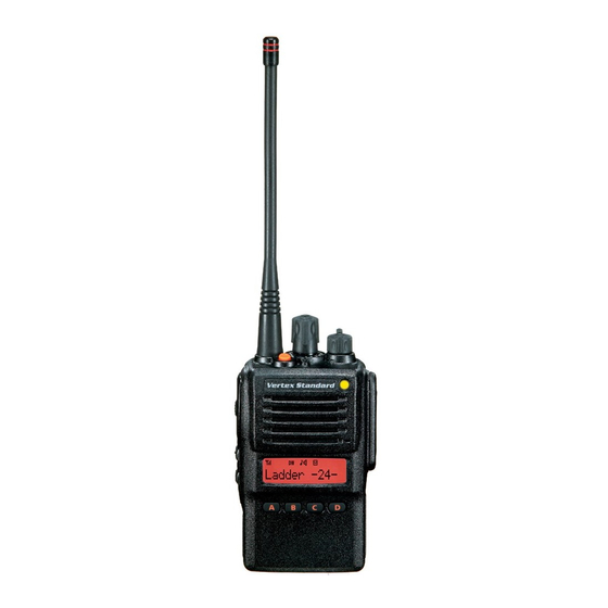
- Page 10 ( 16-K & C ontrol onneCtors ersion LED Indicator VOL/PWR Knob Steady Red: CH ( Channel ) Selector Transmitting in progress Blinking Green: Busy Channel Antenna Jack Steady Green: Tone Squelch in defeated condition TOP SEL Key Dealer Programmed Color ø Emergency, 5-Tone Decoded, or 2-Tone Decoded ø one of “Flashing in white”, “Continuation changes in sequential colors”, or Speaker “Toggling the two colors”. Microphone PTT Switch MIC/SP Jack ( External MIC/SP ) MONITOR Button...
- Page 11 ( 4-K & C ontrol onneCtors ersion LED Indicator VOL/PWR Knob Steady Red: CH ( Channel ) Selector Transmitting in progress Blinking Green: Busy Channel Antenna Jack Steady Green: Tone Squelch in defeated condition TOP SEL Key Dealer Programmed Color ø Emergency, 5-Tone Decoded, or 2-Tone Decoded ø one of “Flashing in white”, “Continuation changes in sequential colors”, or Speaker “Toggling the two colors”. Microphone PTT Switch MIC/SP Jack ( External MIC/SP ) MONITOR Button...
- Page 12 & C -lCd V ontrol onneCtors ersion LED Indicator VOL/PWR Knob Steady Red: CH ( Channel ) Selector Transmitting in progress Blinking Green: Busy Channel Antenna Jack Steady Green: Tone Squelch in defeated condition TOP SEL Key Dealer Programmed Color ø Emergency, 5-Tone Decoded, or 2-Tone Decoded ø one of “Flashing in white”, “Continuation changes in sequential colors”, or Speaker “Toggling the two colors”. Microphone PTT Switch MIC/SP Jack ( External MIC/SP ) MONITOR Button...
- Page 13 ( 16-K lCd i & i & 4-K Cons ndiCators ersions “CALL” Indicator : This channel on the “SCAN” List Receiver Monitor : “Priority Scan” is activated “Talk-Around” is enabled “Dual Watch” is activated “Voice Message” is received Low Transmit Power Mode On Battery Indicator Option Switch ( Key Function ) is activated SUB-LCD : Channel Group Number : Priority Channel : Home Channel RSSI Indicator ( four steps ) : ARTS™ “In Range” : ARTS™ “Out of Range” “Group Scan” is enabled Encryption is activated 12 Character Alpha-numeric Display VX-820 S erieS perating anual...
-
Page 14: Battery Terminals
attery erminals VHF Model UHF Model Maximum Input Voltage: 8.4 V DC 8.4 V DC Maximum Input Current: 2.5 A 2.5 A Maximum Input Power: 21 W 21 W Maximum Internal Capacitance: 50.52 μF 51.32 μF Maximum Internal Inductance: 5.51 μH 5.46 μH VX-820 S erieS perating anual... - Page 15 efore egin Battery Pack Installation and Removal r To remove the battery, turn the radio off and re- move any protective cases. Slide the Battery Pack r To install the battery, hold the transceiver with Latch on the bottom of the radio toward the front your left hand, so your palm is over the speaker panel while sliding the battery down about 1/2 and your thumb is on the top of the belt clip.
-
Page 16: Before You Begin
efore egin Battery Charging ( VAC-UNI: CD-58/PA-55 ) for the FNB-V127LI-UNI/-V128LI-UNI/-V129LI-UNI r Install the Spacer Plate to the nest of the optional CD-58 Desktop Charger, if the Battery Spacer is not installed. r Insert the DC plug from the optional PA-55 AC Adapter into the DC jack on the rear panel of the optional CD-58 Desktop Charger, and then con- AC Line Outlet... - Page 17 FNB-V92LIIS battery, and charge the FNB-V92LIIS battery with the VAC- 920 Desktop Rapid Charger. 3) Use only the Vertex Standard PA-55 AC Adapter. 4) To reduce the risk of explosion, recharge the bat- teries outside of hazardous locations.
-
Page 18: Battery Charging (Vac-920: Cd-31/Pa-42)
efore egin Battery Charging ( VAC-920: CD-31/PA-42 ) for the FNB-V86LIA/-V87LIA/-V92LI/-V92LIIS r Insert the DC plug from the PA-42 AC Adapter into the DC jack on the bottom side of the CD-31 Desktop Rapid Charger, then plug the PA-42 AC Adapter into the AC line outlet. -
Page 19: Low Battery Indication
FNB-V92LIIS battery. voltage is low. 3) Use only the Vertex Standard PA-42 AC Adapter. Caution 4) To reduce the risk of explosion, recharge the bat- Danger of explosion if battery is replaced with teries outside of hazardous locations. -
Page 20: Operation
Note: Some models are programmed so that the operating channels are selected by the Program- mable key and the memory channel group is selected by the CH selector knob. For further de- tails, contact your Vertex Standard dealer. VX-820 S erieS perating... - Page 21 peration r Rotate the VOL/PWR r Press the (Orange) TOP knob to set the volume SEL key to activate one level. If no signal is pres- of the pre programmed ent, press and hold in the f u n c t i o n s w h i c h m a y MONITOR button (under have been enabled at the the PTT switch) more than...
-
Page 22: Automatic Time-Out Timer
peration phone, and vice versa. Automatic Time-Out Timer Do not remove/install the Speaker/Micro- If the selected channel has been programmed for au- phone in a hazardous location. tomatic time-out, you must limit the length of each r If the Busy Channel Lockout feature has been pro- transmission. - Page 23 VX-820 S erieS perating anual...
-
Page 24: Programmable Key Functions
[ A ] , [ B ] , [ C ] , and [ D ] function 22. For further details, contact your Vertex Standard keys. Furthermore, the 16-key version includes the [ Ý ] dealer. - Page 25 dVanCed peration rogrammaBle unCtion TOP SEL MONITOR LAMP [ A ] [ B ] [ C ] [ D ] [ Ý ] [ # ] Call 1 Call 2 Call 3 Call 4 Call 5 Code Up ø Code Down ø Code Set ø Speed Dial ø Option SW 1 Option SW 2 Emergency Home...
-
Page 26: Description Of Operating Functions
dVanCed peration Description of Operating Functions The Scanning feature is used to monitor multiple sig- onitor nals programmed into the transceiver. While scanning, Press the assigned programmable key to cancel the transceiver will check each channel for the pres- CTCSS- and DCS-controlled squelch; the BUSY/TX ence of a signal, and will stop on a channel if a signal indicator will glow green. - Page 27 dVanCed peration ( ta ) atCh round The Dual Watch feature is similar to the SCAN fea- Press the assigned programmable key to activate the ture, except that only two channels are monitored: Talk Around feature when you are operating on du- o The current operating channel;...
- Page 28 dVanCed peration tx s isaBle olloW Press the assigned programmable key to disable the The “Follow-Me” Scan feature checks a User- Transmit Battery Saver, if you are operating in a loca- assigned Priority Channel regularly as you scan other tion where high power is almost always needed. channels.
- Page 29 dVanCed peration You may wish to have the Scanner pass through more olloW atCh than one Group during the scanning process (normally, To set up a “Dual Watch” frequency pair using the scanning is performed within the current group only). “Follow-Me”...
-
Page 30: Dtmf Paging System
dVanCed peration oWn ( 16- oWn ( 16- hannel & 4- & 4- ersion only ersion only Press the assigned programmable key to select a dif- Press the assigned programmable key to select a ferent channel within the current group. 2-tone/5-tone encode code from the pre-defined en- code list. - Page 31 It requires installation of the optional Voice Recording mergenCy Unit. The VX-820 series include an “Emergency” feature Recording; which may be useful for alerting another party moni- Press the assigned programmable key for 1.5 seconds toring on the same frequency as your transceiver’s...
- Page 32 dVanCed peration tatus heCK You can manually adjust the squelch level using this Press the assigned programmable key to check the function: 5-Tone receive status code. When you press this key, r Press the assigned programmable key. A tone will the LCD display will indicate the “Message”...
- Page 33 dVanCed peration ta s hisper Press the assigned programmable key to toggle the TA Press the assigned Programmable key to increase the (Talk Around) scan feature “On” and “Off”. microphone gain; thus you can speak in a low voice (whisper) temporarily. Again press the assigned Pro- While TA scan is proceeding, the VX-820 will search grammable key to resume normal microphone gain.
-
Page 34: Lock
arts™ dtmf p ystem ø aging ange ranspond ystem This system is designed to inform you when you and This system allows paging and selective calling, using another ARTS™-equipped station are within commu- DTMF tone sequences. nication range. When your radio is paged by a station bearing a tone During ARTS™... -
Page 35: User Set Mode
The 16-key and 4-key versions of the VX-820 include splay esCription a “User Set (Menu)” Mode which allows the user to 1 SQL Select the Squelch Threshold Level. 2 SCN List Select the Scan List “User” or “Dealer”. define or configure various settings, such as Beep On/ 3 BEEP Set the Beep On/Off. Off, Squelch Threshold Level, LCD Contrast, etc. 4 BELL Set the Bell On/Off. - Page 36 UHF Antenna (490-512 MHz) LCC-820 Leather Case mportant If any of the IS Exempt Accessory is used with the VX-820 series, the radio is no longer intrinsically safe, and must not be used in haz- ardous locations. VX-820 S erieS...
-
Page 37: Optional Accessories
If any of the IS Exempt Accessory is used Availability of accessories may vary; some accessories with the VX-820 series, the radio is no longer are supplied standard per local requirements, others intrinsically safe, and must not be used in haz- may be unavailable in some regions. Check with your ardous locations. Vertex Standard Dealer for changes to this list. VX-820 S erieS perating anual... -
Page 38: Warranty Policy
Vertex Standard warrants, to the original purchaser only, its Vertex Standard manufactured communications prod- ucts against defects in materials and workmanship under normal use and service for a given period of time from the date of purchase. Limited Warranty Details: North America customers (USA and Canada): http://www.vertexstandard.com/lmr/warranty-terms.aspx... - Page 39 This device complies with Part 15 of the FCC rules. Operation is subject to the condition that this de- vice does not cause harmful interference.
- Page 40 Copyright 2014 Vertex Standard LMR, Inc. All rights reserved. No portion of this manual may be reproduced without the permission of Vertex Standard LMR, Inc. Printed in China...