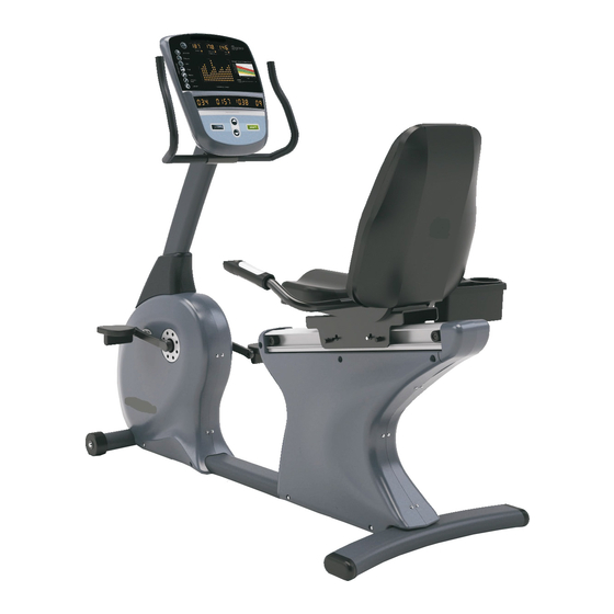
Vision Fitness R70 Service Manual
Hide thumbs
Also See for R70:
- Assembly manual (3 pages) ,
- Owner's manual (48 pages) ,
- Owner's manual (25 pages)

Related Manuals for Vision Fitness R70


Summary of Contents for Vision Fitness R70
- Page 1 It All StArtS wIth A VISIon It All StArtS wIth A VISIon FItneSS™ R 7 0 b i k e S e R V i C e M A N U A l...
-
Page 3: Table Of Contents
TAble of CoNTeNTS CHAPTeR 1: SeRiAl NUMbeR loCATioN ..............CHAPTeR 2: iMPoRTANT SAfeTy iNSTRUCTioNS Before Getting Started ....................2 read and Save these Instructions ................3 electrical requirements .................... 4 CHAPTeR 3: PReVeNTATiVe MAiNTeNANCe recommended Cleaning tips ................... 5 Check for Damaged Parts ..................5 Care and Maintenance Instructions ................ - Page 4 ......................50 7.23 testing the Bike ....................... 51 CHAPTeR 8: bike SPeCifiCATioNS AND ASSeMbly GUiDe Unpacking the r70 Bike .................... 52 Assembly tools ......................53 Assembly Instructions ....................54 Adjusting the Pedal Straps ..................61 Adjusting the Seat ...................... 62...
-
Page 5: Chapter 1: Serial Number Location
CHAPTeR 1: SeRiAl NUMbeR loCATioN 1.1 SeRiAl NUMbeR loCATioN... -
Page 6: Chapter 2: Important Safety Instructions
Please do not place the Vision Fitness r70 Bike in an area of high humidity, such as the vicinity of a steam room, indoor pool, or sauna. -
Page 7: Read And Save These Instructions
Vision Fitness r70 Bike, make sure CAUTioN! Any changes or modifications to this equipment that all users read this manual. remind the users that before undertaking any fitness program, they should obtain complete could void the product warranty. -
Page 8: Electrical Requirements
SelF PowereD FeAtUreS: the Vision Fitness r70 Bike is a self-powered unit, requiring no external power source. when a user pedals at a speed above 20 revolutions per minute, the power is generated to allow the bike to function properly. Because of this self-generating feature, the console feedback will fade away when you cease pedaling. -
Page 9: Chapter 3: Preventative Maintenance
MAiNTAiN lAbelS AND NAMePlATeS. Do not remove labels • P osition the equipment away from direct sunlight. The intense UV light for any reason. they contain important information. If unreadable can cause discoloration on plastics. or missing, contact Vision Fitness for a replacement at 800-335- 4348 or www.visionfitness.com. • L ocate your equipment in an area with cool temperatures and low humidity. -
Page 10: Care And Maintenance Instructions
* teflon based spray lubricant such as "Super lube" or other Vision Fitness approved products. * Mild water soluble detergent such as "Simple Green" or other Vision Fitness approved products * Vacuum cleaner with an extendable hose and crevasse tool attachment. -
Page 11: Chapter 4: Console Overlay And Workout Description
CHAPTeR 4: CoNSole oVeRlAy AND WoRkoUT DeSCRiPTioN 4.1 CoNSole DeSCRiPTioN... -
Page 12: Console Display Descriptions
CHAPTeR 4: CoNSole oVeRlAy AND WoRkoUT DeSCRiPTioN 4.1 CoNSole DeSCRiPTioN - CoNTiNUeD CoNSole DiSPlAy DeSCRiPTioNS START / HolD To ReSeT - Press the StArt key to begin a Manual workout immediately without having to set individual information. when the program begins, you have the ability to adjust resistance levels with the UP or Down Arrow keys. Feedback information will be calculated using the default settings. - Page 13 CHAPTeR 4: CoNSole oVeRlAy AND WoRkoUT DeSCRiPTioN 4.1 CoNSole DeSCRiPTioN - CoNTiNUeD CARDio PoRT A cardio port is located on the back of the console that is compatible to entertainment protocol such as Cardio theater. the bottom port is the active port to use for this function.
-
Page 14: Workout Overview
CHAPTeR 4: CoNSole oVeRlAy AND WoRkoUT DeSCRiPTioN 4.2 WoRkoUT oVeRVieW WoRkoUT oVeRVieW ClASSiCS: MANUAL - Manual is a user controlled program in which the resistance remains as set level unless you decide to change it. INTERVAL - Interval is an efficient workout that strengthens your cardiovascular system by alternating work intervals and recovery intervals. Be sure to challenge yourself with intense work intervals. -
Page 15: Using The Programs
CHAPTeR 4: CoNSole oVeRlAy AND WoRkoUT DeSCRiPTioN 4.3 USiNG THe PRoGRAMS USiNG THe PRoGRAMS SeleCTiNG qUiCk START - the easiest way to begin exercising is to simply press the StArt key (Figure A). You will begin exercising in a Manual resistance program in which you can change the resistance levels to meet your goals. Current default settings will be used to determine exercise feedback. - Page 16 CHAPTeR 4: CoNSole oVeRlAy AND WoRkoUT DeSCRiPTioN 4.3 USiNG THe PRoGRAMS - CoNTiNUeD USiNG THe PRoGRAMS - Continued eNTeRiNG ReSiSTANCe - when prompted by the message center to enter level, use the UP and Down Arrow keys to adjust the displayed resistance level (Figure e).
-
Page 17: Chapter 5: Engineering Mode
CHAPTeR 5: eNGiNeeRiNG MoDe 5.1 eNGiNeeRiNG MoDe the engineering Mode allows the club owner to customize the bike for the club. 1) to enter engineering Mode, press and hold down the UP and Down Arrow keys at the same time for 3-5 seconds. 2) the console will beep 3 times and enter into the engineering Mode menu. -
Page 18: Chapter 6: Troubleshooting
CHAPTeR 6: TRoUbleSHooTiNG 6.1 eleCTRiCAl DiAGRAMS eleCTRiCAl bloCk DiAGRAM... - Page 19 CHAPTeR 6: TRoUbleSHooTiNG 6.1 eleCTRiCAl DiAGRAMS A1 = Console Cable --> MCB G1 A2 = hand Pulse Cable A3 = hand Pulse Cable A4 = Quick Key Cable G1 = 7 Pin terminal to the Console G2 = 4 Pin terminal to the resistor G3 = 5 Pin terminal to the eCB...
- Page 20 CHAPTeR 6: TRoUbleSHooTiNG 6.1 eleCTRiCAl DiAGRAMS P01 - CoNSole CAble...
- Page 21 CHAPTeR 6: TRoUbleSHooTiNG 6.1 eleCTRiCAl DiAGRAMS P04 - PUlSe SeNSoR WiRe...
-
Page 22: Lcb Wiring Instructions
CHAPTeR 6: TRoUbleSHooTiNG 6.2 lCb WiRiNG iNSTRUCTioNS lCb WiRiNG iNSTRUCTioNS D1 - 2 pin terminal to the generator sensor. D2 - 5 pin terminal to the console. D3 - 2 pin terminal to the generator. D4 - 3 pin terminal to the on / off switch. D5 - 2 pin terminal to the battery. -
Page 23: Troubleshooting - Console Power Issues
CHAPTeR 6: TRoUbleSHooTiNG 6.3 TRoUbleSHooTiNG - CoNSole PoWeR iSSUeS No DiSPlAy oN THe CoNSole oR THe DiSPlAy iS DiM PoSSible CAUSeS: 1) the console is damaged or the console cable is not connected properly. 2) Poor connection to the terminals on the lower board. 3) the lower board is damaged. -
Page 24: Troubleshooting - No Or High Resistance
CHAPTeR 6: TRoUbleSHooTiNG 6.4 TRoUbleSHooTiNG - No oR HiGH ReSiSTANCe No ReSiSTANCe CHANGe oR AlWAyS HiGH ReSiSTANCe PoSSible CAUSeS: 1) the console is damaged or the console cable is not connected properly. 2) the console cable is damaged. 3) the eCB is damaged. 4) the lower board is damaged. -
Page 25: Troubleshooting - No Rpm
CHAPTeR 6: TRoUbleSHooTiNG 6.5 TRoUbleSHooTiNG - No RPM DiSPlAyeD No RPM iS DiSPlAyeD DURiNG exeRCiSe PoSSible CAUSeS: 1) the eCB is damaged or the console cable is not connected properly. 2) the console is damaged. 3) the lower board is damaged. SolUTioN: 1) open the side covers and check the lower board leDs. -
Page 26: Troubleshooting - Pedals Slipping
CHAPTeR 6: TRoUbleSHooTiNG 6.6 TRoUbleSHooTiNG - PeDAlS SliPPiNG SliPPiNG WHile PeDAliNG PoSSible CAUSeS 1) Belt tension is not enough. 2) the one way bearing in the secondary pulley axle is damaged. SolUTioN: 1) remove the right side cover and check the drive belt tension. tighten as needed. 2) If the belt tension is correct and the belt is still slipping, the one way bearing in the secondary pulley axle is damaged. -
Page 27: Troubleshooting - Noise Issues
CHAPTeR 6: TRoUbleSHooTiNG 6.7 TRoUbleSHooTiNG - NoiSe iSSUeS kNoCkiNG oR CReAkiNG NoiSeS PoSSible CAUSeS: 1) the pedal is connected to the crank arm too loosely. 2) Belt tension is too loose, or the belt is dirty. 3) the crank is damaged. 4) the crank axle assembly is damaged. -
Page 28: Troubleshooting - Heart Rate Issues
CHAPTeR 6: TRoUbleSHooTiNG 6.8 TRoUbleSHooTiNG - HeART RATe iSSUeS HeART RATe DoeS NoT WoRk PoSSible CAUSeS: 1) not good contact between the user and hr grips or hr strap. 2) the hr strap is at a low battery status. 3) the hr strap is damaged. 4) the hr grips are damaged. -
Page 29: Chapter 7: Part Replacement Guide
CHAPTeR 7: PART RePlACeMeNT GUiDe 7.1 CoNSole bACk CoVeR RePlACeMeNT 1) remove the 4 screws holding the console back cover to the console (Figure A). fiGURe A 2) remove the console back cover (Figure B). fiGURe b 3) reverse Steps 1-2 to install a new console back cover. -
Page 30: Console Replacement
CHAPTeR 7: PART RePlACeMeNT GUiDe 7.2 CoNSole RePlACeMeNT 1) remove the 4 screws holding the console to the console mast (Figure A). 2) Disconnect the 3 wire connections to the console (Figure B). fiGURe A fiGURe b 3) remove the console (Figure C). 4) reverse Steps 1-3 to install a new console. -
Page 31: Stationary Handlebar Replacement
CHAPTeR 7: PART RePlACeMeNT GUiDe 7.3 STATioNARy HANDlebAR RePlACeMeNT 1) remove the 2 screws holding the stationary handlebar to the console mast (Figure A). fiGURe A 2) remove the stationary handlebar (Figure B). fiGURe b 3) reverse Steps 1-2 to install a new stationary handlebar. -
Page 32: Console Mast Replacement
CHAPTeR 7: PART RePlACeMeNT GUiDe 7.4 CoNSole MAST RePlACeMeNT 1) remove the console as outlined in Section 7.2. 2) remove the stationary handlebar as outlined in Section 7.3. 3) lift up the console mast boot (Figure A). fiGURe A 4) remove the 6 screws attaching the console mast to the frame bracket (Figure B). fiGURe b 5) remove the console mast while simultaneously pulling the wire harness and hr wires out the bottom of the mast. -
Page 33: Pedal Replacement
CHAPTeR 7: PART RePlACeMeNT GUiDe 7.5 PeDAl RePlACeMeNT 1) Use a 15mm pedal wrench to turn the pedal - clockwise for the left pedal, counter-clockwise for the right pedal (Figure A). fiGURe A 2) remove the pedal (Figure B). fiGURe b 3) reverse Steps 1-2 to install a new pedal. -
Page 34: Pedal Crank Removal
CHAPTeR 7: PART RePlACeMeNT GUiDe 7.6 PeDAl CRANk ReMoVAl 1) remove the pedals as outlined in Section 7.5. 2) remove the center cover on the crank by turning it counter-clockwise with a flat screwdriver (Figures A & B). fiGURe A fiGURe b 3) remove the 14mm nut and washer exposed by removing the center cover in Step 2 (Figures C &... - Page 35 CHAPTeR 7: PART RePlACeMeNT GUiDe 7.6 PeDAl CRANk ReMoVAl - CoNTiNUeD 4) Use a crank removal tool (Vision Fitness part # ZMS2000030) to remove the crank from the unit (Figures e & F). fiGURe e fiGURe f 5) reverse Steps 1-4 to install a new crank. NOTE: Be sure to tighten the crank nut removed in Step 3 to 70 n-m of torque.
-
Page 36: Front Side Covers Replacement
CHAPTeR 7: PART RePlACeMeNT GUiDe 7.7 fRoNT SiDe CoVeR RePlACeMeNT 1) remove the pedals as outlined in Section 7.5. 2) remove the pedal cranks as outlined in Section 7.6. 3) remove the 9 screws on each of the front side covers (Figure A). fiGURe A 4) remove the front side covers (Figure B shows both front side covers removed). -
Page 37: Drive Belt Replacement
CHAPTeR 7: PART RePlACeMeNT GUiDe 7.8 DRiVe belT RePlACeMeNT 1) remove the right front side cover as outlined in Section 7.7. 2) Disconnect the idler spring from the frame (Figure A). 3) rotate the idler so that tension is removed from the drive belt (Figure B). fiGURe A fiGURe b 4) remove the drive belt (Figure C). -
Page 38: Crank Axle Set Replacement
CHAPTeR 7: PART RePlACeMeNT GUiDe 7.9 CRANk Axle SeT RePlACeMeNT 1) remove both front side covers as outlined in Section 7.7. 2) remove the drive belt as outlined in Section 7.8. 3) remove the snap ring on the left side of the unit holding the crank axle bearings into the frame (Figure A). fiGURe A 4) Use a hammer or mallet to remove the crank axle set from the frame (Figure B). -
Page 39: Generator / Ecb Replacement
CHAPTeR 7: PART RePlACeMeNT GUiDe 7.10 GeNeRAToR / eCb RePlACeMeNT 1) remove both front side covers as outlined in Section 7.7. 2) walk the generator belt off of the secondary axle pulley (Figure A). 3) loosen the large eye hook nut on the generator (Figure B). fiGURe A fiGURe b 4) remove the small eye hook nut on the generator (Figure C). - Page 40 CHAPTeR 7: PART RePlACeMeNT GUiDe 7.10 GeNeRAToR / eCb RePlACeMeNT - CoNTiNUeD 7) Unplug the generator wire harness (Figure e). fiGURe e 8) Slide the generator towards the front of the unit and out of the frame (Figure F). fiGURe f 9) reverse Steps 1-8 to install a new generator.
-
Page 41: Generator / Ecb Belt Replacement
CHAPTeR 7: PART RePlACeMeNT GUiDe 7.11 GeNeRAToR / eCb belT RePlACeMeNT 1) remove both front side covers as outlined in Section 7.7. 2) walk the generator belt off of the secondary axle pulley (Figure A). 3) loosen the large eye hook nut on the generator (Figure B). fiGURe b fiGURe A 4) remove the small eye hook nut on the generator (Figure C). - Page 42 CHAPTeR 7: PART RePlACeMeNT GUiDe 7.11 GeNeRAToR / eCb belT RePlACeMeNT - CoNTiNUeD 7) Slide the generator towards the front of the unit and out of the frame. remove the generator belt from the generator pulley (Figure e). fiGURe e 8) reverse Steps 1-7 to install a new generator belt.
-
Page 43: Secondary (Pulley) Axle Set Replacement
CHAPTeR 7: PART RePlACeMeNT GUiDe 7.12 SeCoNDARy (PUlley) Axle RePlACeMeNT 1) remove both front side covers as outlined in Section 7.7. 2) remove the generator belt as outlined in Section 7.11. 3) remove the screw holding the small clutch pulley in place and remove the clutch pulley (Figures A & B). fiGURe A fiGURe b 4) Use a large crescent wrench or channel lock pliers to remove the secondary axle nut (Figure C). -
Page 44: Cup Holder Replacement
CHAPTeR 7: PART RePlACeMeNT GUiDe 7.13 CUP HolDeR RePlACeMeNT 1) remove the 2 screws holding the cup holder to the heart rate handlebar (Figure A). fiGURe A 2) remove the cup holder (Figure B). fiGURe b 3) reverse Steps 1-2 to install a new cup holder. NOTE: when installing the screws removed in Step 2, be careful not to damage the heart rate grip wiring. -
Page 45: Seat Adjustment Handle Replacement
CHAPTeR 7: PART RePlACeMeNT GUiDe 7.14 SeAT ADjUSTMeNT HANDle RePlACeMeNT 1) remove the 2 screws holding the seat adjustment handle to the frame (Figure A). fiGURe A 2) remove the seat adjustment handle (Figure B). fiGURe A 3) reverse Steps 1-2 to install a new seat adjustment handle. -
Page 46: Seat Pad Replacement
CHAPTeR 7: PART RePlACeMeNT GUiDe 7.15 SeAT PAD RePlACeMeNT 1) remove the 4 screws holding the seat pad to the upper seat frame (Figure A). fiGURe A 2) remove the seat pad (Figure B). fiGURe b 3) reverse Steps 1-2 to install a new seat pad. -
Page 47: Back Pad Replacement
CHAPTeR 7: PART RePlACeMeNT GUiDe 7.16 bACk PAD RePlACeMeNT 1) remove the back pad cover. It is held on snap clips and can be removed without using any tools (Figure A). 2) remove the 4 screws holding the back pad to the upper seat frame (Figure B). fiGURe A fiGURe b 3) remove the back pad (Figure C). -
Page 48: Heart Rate Handlebar Replacement
CHAPTeR 7: PART RePlACeMeNT GUiDe 7.17 HeART RATe HANDlebAR RePlACeMeNT 1) remove the seat pad as outlined in Section 7.15. 2) remove the back pad as outlined in Section 7.16. 3) remove the 4 screws attaching the heart rate handlebar to the upper seat frame (Figure A). fiGURe A 4) Disconnect the 2 wires coming through the lower seat frame to the heart rate handlebar and remove it (Figure B). -
Page 49: Upper Seat Frame Replacement
CHAPTeR 7: PART RePlACeMeNT GUiDe 7.18 UPPeR SeAT fRAMe RePlACeMeNT 1) remove the seat pad as outlined in Section 7.15. . 2) remove the back pad as outlined in Section 7.16. 3) remove the heart rate handlebar as outlined in Section 7.17. 4) remove the 4 screws holding the upper seat frame to the lower seat frame (Figure A). -
Page 50: Lower Seat Frame Replacement
CHAPTeR 7: PART RePlACeMeNT GUiDe 7.19 loWeR SeAT fRAMe RePlACeMeNT 1) remove the seat pad as outlined in Section 7.15. . 2) remove the back pad as outlined in Section 7.16. 3) remove the heart rate handlebar as outlined in Section 7.17. 4) remove the upper seat frame as outlined in Section 7.18. - Page 51 CHAPTeR 7: PART RePlACeMeNT GUiDe 7.19 loWeR SeAT fRAMe RePlACeMeNT - CoNTiNUeD 8) Cut the wire ties attaching the heart rate handlebar wires to the lower seat frame (Figure e). fiGURe e 9) Depress the seat adjustment handle and slide the lower seat frame out the back of the seat slide assembly and off the unit (Figure F). fiGURe f 10) reverse Steps 1-9 to install a new lower seat frame.
-
Page 52: Heart Rate Grips Replacement
CHAPTeR 7: PART RePlACeMeNT GUiDe 7.20 HeART RATe GRiP RePlACeMeNT 1) remove the 3 screws going upward into the top of the heart rate grip (Figure A). 2) Pull apart the top and bottom portions of the heart rate grip (Figure B). fiGURe A fiGURe b 3) Disconnect the keypad and heart rate sensor wires from the grip and remove it from the heart rate handlebar (Figure C). -
Page 53: Rear Side Covers Removal
CHAPTeR 7: PART RePlACeMeNT GUiDe 7.21 ReAR SiDe CoVeR RePlACeMeNT 1) remove the 9 screws holding the right rear side cover and 10 screws holding the left rear side cover onto the frame (Figure A). fiGURe A 2) remove the rear side covers (Figure B shows the unit with both rear side covers removed). fiGURe b 3) reverse Steps 1-2 to install new rear side covers. -
Page 54: Lcb Replacement
CHAPTeR 7: PART RePlACeMeNT GUiDe 7.22 loWeR CoNTRol boARD RePlACeMeNT 1) remove the left rear side cover as outlined in Section 7.21. . 2) remove the 3 screws holding the cover onto the lower control board (Figure A). 3) Disconnect the 3 wires that are plugged into the lower control board (Figure B). fiGURe A fiGURe b 4) remove the 2 screws attaching the lower control board to the frame (Figure C). -
Page 55: Testing The Bike
CHAPTeR 7: PART RePlACeMeNT GUiDe 7.23 TeSTiNG THe bike onCe the UnIt or rePlACeMent PArt IS FUllY InStAlleD AnD ASSeMBleD AnD ProPerlY PlACeD on the Floor, USe the FollowInG InStrUCtIonS to teSt the MAChIne: 1) without hitting start or entering any program modes, sit on the bike and hold the handlebars while pedaling to simulate exercising. while moving, listen for any odd noises or squeaks. -
Page 56: Chapter 8: Bike Specifications And Assembly Guide
CHAPTeR 8: bike SPeCifiCATioNS AND ASSeMbly GUiDe 8.1 UNPACkiNG THe bike the Vision Fitness r70 Bike is carefully inspected before shipment, so it should arrive in good operating condition. Vision Fitness ships the bike in the following pieces: NOTE : If these parts are missing from the package, please contact Vision Fitness at 1-800-335-4348. -
Page 57: Assembly Tools
CHAPTeR 8: bike SPeCifiCATioNS AND ASSeMbly GUiDe 8.2 ASSeMbly ToolS ToolS ReqUiReD foR ASSeMbly 4mm l-Shaped Allen wrench 5mm l-Shaped Allen wrench 5mm t-handled Allen wrench Phillips Screwdriver 15mm Pedal wrench... -
Page 58: Assembly Instructions
CHAPTeR 8: bike SPeCifiCATioNS AND ASSeMbly GUiDe 8.3 ASSeMbly iNSTRUCTioNS STeP 1 - oRANGe bAG 1) Install the rear foot with four lock washers (M8), two inside bolts (M8 x 65l), and two outside bolts (M8 x 20l). tighten with the 5mm t-Shaped Allen wrench. - Page 59 CHAPTeR 8: bike SPeCifiCATioNS AND ASSeMbly GUiDe 8.3 ASSeMbly iNSTRUCTioNS - CoNTiNUeD STeP 2 - blUe bAG 1) Slide the console mast boot onto the console mast. 2) Unfold the wire harness and heart rate wires located in the console mast frame bracket. Attach the wire tie coming from the bottom of the console mast to the wire harness and heart rate wires.
- Page 60 CHAPTeR 8: bike SPeCifiCATioNS AND ASSeMbly GUiDe 8.3 ASSeMbly iNSTRUCTioNS - CoNTiNUeD STeP 3 - PiNk bAG 1) Mount the upper handlebars to the console mast using two lock washers (M8) and two bolts (M8 x 15l). tighten with the 5mm t-Shaped Allen wrench.
- Page 61 CHAPTeR 8: bike SPeCifiCATioNS AND ASSeMbly GUiDe 8.3 ASSeMbly iNSTRUCTioNS - CoNTiNUeD STeP 4 - GReeN bAG 1) remove the two socket head bolts from the sliding seat adjustment bracket. Slide the seat adjustment handle between the teeth of the seat adjustment bracket.
- Page 62 CHAPTeR 8: bike SPeCifiCATioNS AND ASSeMbly GUiDe 8.3 ASSeMbly iNSTRUCTioNS - CoNTiNUeD STeP 5 - blACk bAG 1) Mount the seat bottom and seat back to the seat frame with four bolts to the seat frame with four bolts (M6 x 55l) and four lock washers (M6).
- Page 63 CHAPTeR 8: bike SPeCifiCATioNS AND ASSeMbly GUiDe 8.3 ASSeMbly iNSTRUCTioNS - CoNTiNUeD STeP 6 - yelloW bAG 1) Attach the left and right pedals to the left and right crank arms. tighten the pedals using the 15mm Pedal wrench. 2) Secure the Accessory tray to the seat handlebar with two bolts (M5 x 35l) and two lock washers (M5). Be careful when inserting the bolts to clear the wires inside the handlebar to prevent damage.
- Page 64 CHAPTeR 8: bike SPeCifiCATioNS AND ASSeMbly GUiDe 8.3 ASSeMbly iNSTRUCTioNS - CoNTiNUeD FInAl ASSeMBlY...
-
Page 65: Adjusting The Pedal Straps
CHAPTeR 8: bike SPeCifiCATioNS AND ASSeMbly GUiDe 8.4 ADjUSTiNG THe PeDAl STRAPS ADjUSTiNG THe PeDAl STRAPS the straps are designed to fit your individual foot size and should be adjusted tight enough to keep your foot from slipping. the pedals include spring loaded clips for easy adjustment. -
Page 66: Adjusting The Seat
CHAPTeR 8: bike SPeCifiCATioNS AND ASSeMbly GUiDe 8.5 ADjUSTiNG THe SeAT SeAT PoSiTioNiNG to determine the proper seat position, sit on the seat and position the ball of your foot on the center of the pedal. Your knee should bend slightly at the furthest pedal position. You should be able to pedal without locking your knees or shifting your weight side to side. -
Page 67: Leveling The Bike
CHAPTeR 8: bike SPeCifiCATioNS AND ASSeMbly GUiDe 8.6 STAbiliZiNG THe bike STAbiliZiNG THe ViSioN fiTNeSS R70 bike After positioning the bike in its intended location, check its stability by attempting to shake it side to side. Shaking or wobbling indicates that your bike needs to be leveled. - Page 68 NoTeS...
- Page 69 It All StArtS wIth A VISIon ™ Vi SioN fiTN eS S SyS TeMS C oR P. 1610 lAn DMAr K Dr IV e C ottA Ge Gr o Ve wI 53 527 U SA w w w. v i s i o n f i t n e s s . c o m toll F ree 800.335.4348 FA x 60 8.