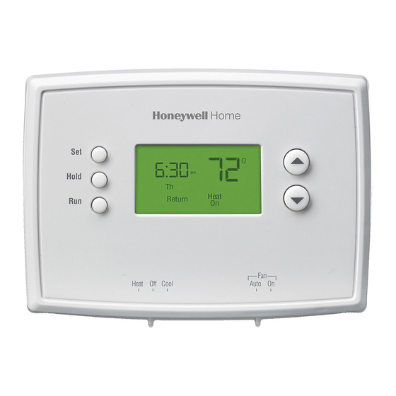
Honeywell RTH2510 Quick Installation Manual
7-day programmable thermostat
Hide thumbs
Also See for RTH2510:
- User manual ,
- Quick installation manual (60 pages) ,
- Operating manual (52 pages)
Table of Contents
Advertisement
Available languages
Available languages
Advertisement
Table of Contents

Related Manuals for Honeywell RTH2510


Summary of Contents for Honeywell RTH2510
- Page 1 Quick Installation Guide RTH2510 7-day Programmable Thermostat...
- Page 2 Do you need assistance? We are here to help. Call 1-800-468-1502.
- Page 3 Programmable Thermostat RTH2510 Identify System Type This thermostat is compatible with the following systems: • Gas, oil or electric furnace • Central air conditioner • Hot water system with or without pump • Millivolt system • Central heating and cooling system •...
-
Page 4: Remove Old Thermostat
Quick Installation Guide Remove Old Thermostat Turn power off at the heating/cooling system. Remove old thermostat, but leave wallplate with wires attached. Do not remove wallplate yet. MERCURY NOTICE: Do not put your old thermostat in the trash if it contains mercury in a sealed tube. -
Page 5: Identify Wires
Programmable Thermostat RTH2510 Identify Wires If any wires are not attached to your old thermostat or are attached to a terminal marked C or C1, they will not be connected to your new thermostat. Wrap the bare metal end of each of these wires with electrical tape, so it cannot touch and short other wires. -
Page 6: Mount New Wallplate
Quick Installation Guide Mount New Wallplate Loosen the locking screw at the bottom of the thermostat. Note that the screw is captive and cannot be removed from the wallplate. Separate the thermostat from the wallplate as per Figure 1. Position the wallplate against the wall and mark hole positions with a pencil. -
Page 7: Connect Wires
Programmable Thermostat RTH2510 Connect Wires Conventional Systems (Typical Wiring) Match each labeled wire with the terminal having the same letter. Loosen the terminal screws using a screwdriver, insert the wires, then tighten the screws. Push any excess wire back into the wall opening. - Page 8 Quick Installation Guide Connect Wires (cont’d) Conventional Systems (Alternate Wiring) Do not use C, C1 or X wire. Do not use B wire if you already have O wire. Wrap bare end of wire with electrical tape. This thermostat cannot be used if your old thermostat had any two of the following wires: R, RC, RH, 4 and V.
- Page 9 Programmable Thermostat RTH2510 Connect Wires (cont’d) Heat Pump Systems with Auxiliary/Backup Heat (Typical Wiring) Match each labeled wire with the terminal having the same letter. Loosen the terminal screws using a screwdriver, insert the wires, then tighten the screws. Push any excess wire back into the wall opening.
-
Page 10: Alternate Wiring
Quick Installation Guide Connect Wires (cont’d) Heat Pump Systems with Auxiliary/Backup Heat (Alternate Wiring) If your old thermostat had E and Aux wires (or alternate wires), connect both wires to AUX terminal. Do not use L wire. Wrap bare end of wire with electrical tape. Do not use C or X wire. -
Page 11: Set Heating Fan Control
Programmable Thermostat RTH2510 Set Heating Fan Control Set jumper JP1, on the back of the thermostat, if you have connected a wire to the G terminal. Leave the jumper in this factory-set position if you have a gas or oil furnace. - Page 12 Quick Installation Guide Set Heat Pump Reversing Valve Set jumper JP2, on the back of the thermostat, if you have a heat pump. Leave the jumper in this factory-set position if you have connected O wire to the O/B terminal. Place the jumper to this position if you have connected B wire to the O/B terminal.
-
Page 13: Install Batteries And Thermostat
Programmable Thermostat RTH2510 Install Batteries and Thermostat Install 2 AAA batteries on the back of the thermostat. Align the two brackets on the top of the thermostat with the corresponding slots on the top of the wallplate. Push the thermostat against the wallplate. -
Page 14: System Setup
Quick Installation Guide System Setup Follow the procedure below to personalize and configure the thermostat according to the heating/ cooling system. Press the Up and Down buttons simultaneously (for three seconds) until the display appears as shown below. See table on the next page. Function number Option... - Page 15 Programmable Thermostat RTH2510 System Setup (cont’d) Default Function Options setting Temperature 0: Fahrenheit display format 1: Celsius 0: 12-hour display 2 Time display format 1: 24-hour display 2 to 6 cycles per hour • 2: 30 min (steam, gravity) • 3: 20 min (hot water, 90%+...
- Page 16 Automation and Control Systems Honeywell International Inc. 1985 Douglas Drive North Golden Valley, MN 55422 Honeywell Limited 35 Dynamic Drive Scarborough, Ontario M1V 4Z9 http://DIYthermostats.honeywell.com Printed in USA 69-2380ES-01 10-09...
-
Page 17: Guía De Instalación Rápida
Guía de instalación rápida RTH2510 Termostato programable para 7 días... - Page 18 ¿Necesita ayuda? ¡Aquí estamos! LLame al 1-800-468-1502...
-
Page 19: Identificar El Tipo De Sistema
Termostato programable RTH2510 Identificar el tipo de sistema Este termostato es compatible con los siguientes sistemas: • Calefactor a gas, aceite o eléctrico • Aire acondicionado central • Sistema de agua caliente con o sin bomba • Sistema de milivoltios •... -
Page 20: Retirar El Viejo Termostato
Guía de instalación rápida Retirar el viejo termostato Cortar la electricidad del sistema de calefacción/ aire acondicionado. Retirar el viejo termostato pero dejar la placa mural con los cables conectados. No retirar la placa mural todavía ADVERTENCIA SOBRE EL MERCURIO No arrojar el viejo termostato a la basura si contiene mercurio en un tubo sellado. -
Page 21: Identificar Los Cables
Termostato programable RTH2510 Identificar los cables Si en el viejo termostato hubiera cables no conectados o conectados a un terminal marcado C o C1, estos cables no se usarán con el nuevo termostato. Recubrir el extremo de metal desnudo de cada uno con cinta aisladora para que no puedan tocarse y producir un corto circuito. - Page 22 Guía de instalación rápida Instalar la nueva placa mural Aflojar los tornillos de la base del termostato. El tornillo está cautivo y no se lo puede retirar de la base. Separar el termostato de la placa mural como se indica en la Figura 1.
-
Page 23: Conectar Los Cables
Termostato programable RTH2510 Conectar los cables Sistemas convencionales (conexión típica) Hacer coincidir cada cable etiquetado con el terminal de la misma letra. Aflojar los tornillos del terminal con un destornillador, introducir los cables y reajustar los tornillos. Empujar el exceso de cables en el agujero de la pared. - Page 24 Guía de instalación rápida Conectar los cables (cont.) Sistemas convencionales (conexión alternativa) No usar los cables C, C1 o X. No usar el cable B si ya existe un cable O. Envolver el extremo desnudo de los cables con cinta aisladora. No puede usarse este termostato si el viejo termostato tuviera dos de los siguientes cables: R, RC, RH, 4 y V.
- Page 25 Termostato programable RTH2510 Conectar los cables (cont.) Sistemas de bombas de calor con calefactor auxiliar (conexión típica) Hacer coincidir cada cable etiquetado con el terminal de la misma letra. Aflojar los tornillos del terminal con un destornillador, introducir los cables y reajustar los tornillos.
- Page 26 Guía de instalación rápida Conectar los cables (cont.) Sistemas de bombas de calor con calefactor auxiliar (conexión alternativa) Si el viejo termostato tiene cables E y Aux (o cables alternativos), conectar ambos cables al terminal AUX. No usar el cable L. Envolver el extremo desnudo con cinta aisladora.
- Page 27 Termostato programable RTH2510 Ajuste del control del ventilador de la calefacción Ajustar el puente JP1, en la parte de atrás del termos- tato, si se conectó un cable al terminal G. Dejar el puente en este ajuste de fábrica en el caso de una estufa a gas o a aceite.
- Page 28 Guía de instalación rápida Ajuste de la válvula de inversión Ajustar el puente JP2, en la parte de atrás del termos- tato, en el caso de una bomba de calor. Dejar el puente en este ajuste de fábrica si hay un cable O conectado al terminal O/B. Poner el puente en esta posición si hay un cable B conectado al terminal O/B.
- Page 29 Termostato programable RTH2510 Instalación de las pilas y del termostato Instalar 2 pilas AAA en la parte de atrás del termostato. Alinear las dos lengüetas de la parte superior del termostato con las ranuras correspondientes de la parte superior de la placa mural.
- Page 30 Guía de instalación rápida Configuración del sistema El procedimiento a continuación permite personalizar y configurar el termostato según el sistema de calefacción/enfriamiento. Presionar los botones Arriba y Abajo al mismo tiempo (3 seg.) hasta que se vea lo que se indica en la ilustración.
- Page 31 Termostato programable RTH2510 Configuración del sistema (cont.) Ajuste Función Opciones defecto Formato de la 0: Fahrenheit temperatura 1: Celsius 0: 12 horas 2 Formato de la hora 1: 24 horas 2 a 6 ciclos por hora • 2: 30 min. (vapor, gravedad) •...
- Page 32 Sistemas para automatización y control Honeywell International Inc. 1985 Douglas Drive North Golden Valley, MN 55422 Honeywell Limited 35 Dynamic Drive Scarborough, Ontario M1V 4Z9 http://DIYthermostats.honeywell.com Impreso en EE.UU. 69-2380ES-01 10-09...