Table of Contents
Advertisement
Quick Links
SERVICE MANUAL
Ver 1.0 2001. 02
Sony Corporation
9-873-088-11
2001B1600-1
Audio Entertainment Group
© 2001.2
General Engineering Dept.
SPECIFICATIONS
Tape
(normal position type)
Recording system
2-track 1-channel monaural
Speaker
7
Approx. 3.6 cm (1
⁄
in.) dia.
16
Tape speed
15
15
2.4 cm/s (
⁄
ips), 1.2 cm/s (
⁄
16
32
Frequency range
300 – 4,000 Hz (with TAPE SPEED switch at 2.4 cm/s)
Output
Earphone jack (minijack) for 8 – 300 ohms earphone
Power output (at 10% harmonic distortion)
250 mW
Power requirements
3 V DC batteries R6 (size AA) × 2/External DC 3V power sources
Dimensions (w/h/d)
Approx. 62.2 × 121.5 × 24.3 mm (2
parts and controls
Mass
Approx. 125 g (4.5 oz)
Supplied accessories
Microcassette tape MC-30 (1) (Europe only)
Design and specifications are subject to change without notice.
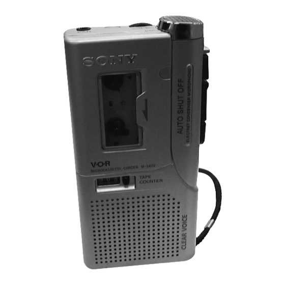
M-540V
East European Model
Model Name Using Similar Mechanism
Tape Transport Mechanism Type
ips)
× 4
×
1
7
31
⁄
⁄
⁄
in.) incl. projecting
2
8
32
MICROCASSETTE
E Model
Chinese Model
M-530V/535V/630V
MZ-530V-99
TM
-CORDER
Advertisement
Table of Contents

Related Manuals for Sony M-540V


Summary of Contents for Sony M-540V
- Page 1 M-540V SERVICE MANUAL E Model Chinese Model Ver 1.0 2001. 02 East European Model Model Name Using Similar Mechanism M-530V/535V/630V Tape Transport Mechanism Type MZ-530V-99 SPECIFICATIONS Tape (normal position type) Recording system 2-track 1-channel monaural Speaker Approx. 3.6 cm (1 ⁄...
-
Page 2: Table Of Contents
M-540V TABLE OF CONTENTS 1. GENERAL ..............2. DISASSEMBLY 2-1. Lid Assy, Cassette ............4 2-2. Lid, Battery Case ............5 2-3. Cabinet (Rear) Assy ............5 2-4. Main Board ..............6 2-5. Mechanism Deck ............6 2-6. Head, Ceramic (HRPE901) ..........7 3. -
Page 3: General
(you can save tapes and batteries). arrow. H : To record at meeting or in a quiet and/or spacious place. The REC/BATT (M-540V) or BATT (M- L : To record for dictation or in a noisy place. 430) lamp, or BATT lamps (M-640V) go When the sound is not loud enough, set it to OFF, or the unit off. -
Page 4: Disassembly
M-540V SECTION 2 DISASSEMBLY • The equipment can be removed using the following procedure. Lid assy, Cabinet (rear) Main Mechanism Head, cassette assy board deck ceramic (HRPE901) Lid, battery case Note : Follow the disassembly procedure in the numerical order given. -
Page 5: Lid, Battery Case
M-540V 2-2. LID, BATTERY CASE 3 two claws 4 lid, battery case 2-3. CABINET (REAR) ASSY Note : When installing, fit the knobs and switches. 1 two screw (1.7x16) 3 screw (B1.7x5), tapping 2 two screw (1.7x16) 5 claw 6 cabinet (rear) assy... -
Page 6: Main Board
M-540V 2-4. MAIN BOARD 7 (M1.4x3.0), locking 1 Unsolder the 2 places. 2 Unsolder the 2 places. 8 (M1.4x3.0), locking 3 Unsolder the 4 places. 5 mic assy 4 Unsolder the 2 places. qa MAIN board 5 Unsolder the 2 places. -
Page 7: Head, Ceramic (Hrpe901)
M-540V 2-6. HEAD, CERAMIC (HRPE901) 2 arm (pinch roller) assy 3 M1.4, special head 4 M1.4, special head 5 head, ceramic 1 claw (HRPE901) -
Page 8: Mechanical Adjustments
M-540V SECTION 3 SECTION 4 MECHANICAL ADJUSTMENTS ELECTRICAL ADJUSTMENTS PRECAUTION Test Tape 1. Clean the following parts with a denatured-alcohol-moistened Tape Speed swab : Type Signal Used for (cm/s) record/playback/erase head pinch roller rubber belts capstan S-2-A030 3 kHz, – 20 dB Head Azimuth Adjustment 2. - Page 9 M-540V Tape Speed Adjustment Adjustment Location : First remove the plate, blind. Setting: VOL control : mechanical mid Remove the VOR switch : OFF plate, blind. Procedure: • Reform 1.2 cm/s speed adjustment before 2.4 cm/s speed adjustment mode : playback...
-
Page 10: Diagrams
M-540V SECTION 5 DIAGRAMS • IC Block Diagrams IC101 LA4168ML-TE-L PAUSE 2.2k Vref R, F SPEED POWER 300k... -
Page 11: Block Diagram
M-540V 5-1. BLOCK DIAGRAM IC101 (1/2) REC/PB AMP MIC901 RV101 MIC IN (MICROPHONE) PRE OUT S101(3/4) IC101 (2/2) – (REC/PB) POWER AMP Q101 POW IN POW OUT2 ALC SWITCH J101 S101(4/4) S103 (REC/PB) SP901 HRPE901 (SPEAKER) REC/PB/ERASE POW OUT1 S101(2/4) -
Page 12: Printed Wiring Board
M-540V 5-2. PRINTED WIRING BOARD • Semiconductor Location Ref. No. Location D102 D103 IC101 Q101 Q102 Q103 Q104 Q105 Q106 Q107 IC101 Q108 Q109 Q110 Q111 Q112 RV101 Q113 VOL w HD + HD – HE + HE – REC / BATT Note: •... -
Page 13: Schematic Diagram
M-540V 5-3. SCHEMATIC DIAGRAM • Refer to page 10 for IC Block Diagrams. REC / BATT Note: • All capacitors are in µF unless otherwise noted. pF: µµF • Voltage is dc with respect to ground under no-signal 50 WV or less are not indicated except for electrolytics condition. -
Page 14: Exploded Views
M-540V SECTION 6 EXPLODED VIEWS NOTE: 6-2. MECHANISM DECK SECTION • -XX and -X mean standardized parts, so • Accessories and packing materials are • The mechanical parts with no reference (MZ-530V-99) they may have some difference from the given in the last of this parts list. -
Page 15: Electrical Parts List
M-540V SECTION 7 MAIN ELECTRICAL PARTS LIST NOTE: • Due to standardization, replacements in the • CAPACITORS: • SEMICONDUCTORS uF: µF In each case, u: µ, for example: parts list may be different from the parts uA...: µA... , uPA... , µPA... , specified in the diagrams or the components •... - Page 16 M-540V MAIN Ref. No. Part No. Description Remarks Ref. No. Part No. Description Remarks < RESISTOR > R605 1-216-823-11 METAL CHIP 1.5K 1/16W R607 1-216-821-11 METAL CHIP 1/16W R101 1-216-829-11 METAL CHIP 4.7K 1/16W R608 1-216-829-11 METAL CHIP 4.7K 1/16W...
- Page 17 M-540V MEMO...
- Page 18 M-540V REVISION HISTORY Clicking the version allows you to jump to the revised page. Also, clicking the version at the upper right on the revised page allows you to jump to the next revised page. Ver. Date Description of Revision...