
Related Manuals for Lowrance GlobalMap 3500C


Summary of Contents for Lowrance GlobalMap 3500C
-
Page 1: Operation Instructions
Pub. 988-0156-081 www.lowrance.com GlobalMap 3500C ® Mapping GPS Receiver Operation Instructions... - Page 2 All screens in this manual are simulated. For free owner's manuals and the most current information on this product, its operation and accessories, All rights reserved. 3500C are registered trademarks of visit our web site: www.lowrance.com Lowrance Electronics Inc. 12000 E. Skelly Dr.
-
Page 3: Table Of Contents
Navigate to Cursor Position on Map... 44 Navigate to a Point of Interest... 45 Creating and Saving a Trail... 46 Displaying a Saved Trail ... 48 Navigating Trails... 48 Visual Trailing ... 49 Table of Contents 3500C ... 2... - Page 4 Navigate a Trail (forward)... 49 Navigate a Back Trail (backtrack, or reverse)... 51 Transfer Custom Maps and GPS Data Files ... 52 Custom Maps:... 52 GPS Data files: ... 52 Cancel Navigation ... 54 Section 4: Advanced GPS Operations... 55 Find Distance From Current Position to Another Location ...
- Page 5 Configure NMEA ... 71 Coordinate System Selection ... 72 To setup Loran TD: ... 73 Map Fix ... 73 To configure a map fix: ... 74 Customize Page Displays ... 75 GPS Simulator ... 76 To get to the GPS Simulator:... 76 Simulating Trail or Route Navigation ...
- Page 6 Trail Visible/Invisible and Other Trail Options ... 99 Transparency ... 99 Units of Measure ... 100 Section 6: Searching ... 101 Find Addresses ... 101 Find Any Item Selected by Map Cursor ... 104 Find Interstate Highway Exits ... 105 Find Map Places or Points of Interest (POI) ...
-
Page 7: Section 1: Read Me First
Section 3 covers Basic GPS Operation. It will show you how easy it is to run the GlobalMap 3500C, right out of the box. This section features a one-page GPS Quick Reference. (If you've already jumped ahead and figured out how to install the unit yourself, and you just... -
Page 8: Capabilities And Specifications: Globalmap 3500C
GPS options in Section 5, System Setup and GPS Setup Options. Section 5 is organized in alphabetical order. In Section 6, we go into more detail on one of the GlobalMap 3500C's most remarkable capabilities — Searching. We'll introduce a search... - Page 9 Case size:... 5.4" H x 6.9" W x 3.4" D (13.8 x 17.6 x 8.6 MMC slots: ... One with waterproof door (SD card compati- Recording:... MMC & SD memory cards for recording GPS Back-up memory: ... Built-in memory stores GPS data for dec- Languages:...
-
Page 10: How Lowrance Gps Works
How Lowrance GPS Works You'll navigate faster and easier if you understand how the GlobalMap 3500C scans the sky to tell you where you are on the earth — and, where you're going. (But if you already have a working understanding of GPS receivers and the GPS navigation system, skip on ahead to Sec- tion 2, Installation &... - Page 11 GPS Data Files (file format *.usr) can be shared be- tween Lowrance GPS or sonar/GPS units or even personal computers. This GlobalMap 3500C has one more thing in common with a personal computer. Just as computers have a floppy disk drive for storing and ex- changing files, the unit has a slot for an MMC (MultiMedia Card) or SDC (Secure Digital card) flash memory card.
-
Page 12: Introduction To Gps And Waas
Section 2, Installation & Accessories, on page 11, so you can mount your GlobalMap 3500C and plug in the power. Or you might want to see how our text formatting makes the manual tuto- rials easy to skim. - Page 13 Speed, direction of travel, and distance are all calculated from position information. Therefore, in order for the GlobalMap 3500C to determine direction of travel, you must be moving and the faster, the better. This is not to say that it won’t work at walk- ing or trolling speeds —...
-
Page 14: How To Use This Manual: Typographical Conventions
WAAS reception, but terrain, foliage or even large man-made structures frequently block the WAAS signal from ground receivers. You'll find that using your GPS receiver is both easy and amazingly accurate. It’s easily the most accurate method of electronic navigation available to the general public today. - Page 15 2. Press ↓ to Trail 1| 3. You are asked to wait while it converts the trail into a route. 4. The wait message disappears and the GlobalMap 3500C begins showing navigation information along the trail. Now, begin moving and follow your GlobalMap 3500C.
- Page 16 Notes...
-
Page 17: Section 2: Installation & Accessories
Installation & Accessories Preparations You can install the GPS system in some other order if you prefer, but we recommend this installation sequence: Caution: You should read over this entire installation section before drill- ing any holes in your vehicle or vessel! 1. -
Page 18: Power Connections
You need to select an antenna installation location that has a clear, un- obstructed view of the sky. After the module is installed, connect it to the end of the Y-adapter extension cable as shown in the following dia- gram. To connect it to the unit, insert the cable's splitter plug into the Network socket on the back of the unit and your system is ready to use. - Page 19 To unit The Power/Data cable for this unit. Depending on your configuration, you may not use all of these wires. (For example, many units cannot operate an optional external speaker, so the white wire on the Power Supply cable isn't functional.) The fol- lowing segments include instructions for installing all the wires that you will use with this unit.
- Page 20 with electrical interference. Therefore, it's safer to go ahead and attach the power cable directly to the battery. CAUTION: When using the unit in a saltwater environment, we strongly rec- ommend that you shut off the power supply to the power cable when the unit is not in use.
-
Page 21: Nmea 0183 Cable Connections
Power cable to the boat's battery. Data Cable Power connections for the GlobalMap 3500C GPS unit. NOTE: If you're powering a NMEA-2000 buss, you will attach both the NMEA-2000 Power cable and the unit's Power Supply cable to the boat's battery. To attach the NMEA-2000 Power cable, connect the red wire to battery's + and black and shield wires to battery's -. -
Page 22: Nmea Wiring
NMEA-compatible device. Mounting the Unit: Bracket, In-Dash or Portable You can install the GlobalMap 3500C on the top of a dash with the supplied gimbal bracket. It can also be installed in the dash or mounted on a portable power supply. - Page 23 Mount the GlobalMap 3500C in any convenient location, provided there is clearance behind the unit when it's tilted for the best viewing angle. You should also make sure there is enough room behind the GlobalMap 3500C to attach the power and GPS antenna/receiver module cables. (A drawing on the next page shows the dimensions of a gimbal-mounted GlobalMap 3500C.)
- Page 24 GlobalMap 3500C. If you choose to fill in the hole, be sure to position the cables against the rear edge of the hole as you apply the fill material.
- Page 25 In-Dash Installation You can mount the GlobalMap 3500C in the dash with an optional FM-5 In-Dash Adapter Kit. The kit includes mounting hardware, a template for cutting the hole and an instruction sheet, part 988-0147-43. In-dash mounting template for the GlobalMap 3500C, showing dimensions.
-
Page 26: Mmc Or Sd Card Memory Card Installation
MMC or SD Card Memory Card Installation Your GlobalMap 3500C uses a MultiMedia Card to store information, such as custom maps, waypoints, trails and other GPS data. The unit can also use Secure Digital Cards (SD card or SDC) to store data. -
Page 27: Other Accessories
MapCreate™ 6 CD-ROM, left; MMC card reader for USB ports, right. Now that you have your GlobalMap 3500C installed, move on to Section 3, Basic GPS Operations. There, we'll present a series of step-by-step tutorials to teach you the basics of GPS navigation. - Page 28 Notes...
-
Page 29: Section 3: Basic Gps Operations
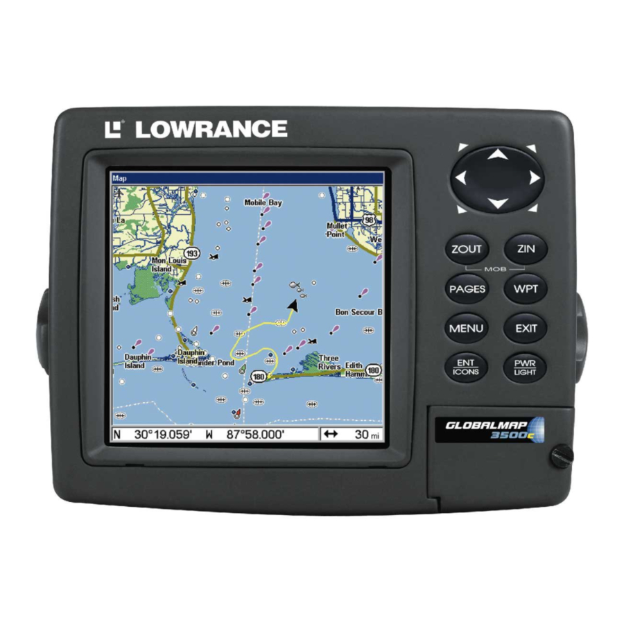
Quick Reference on page 36. Keyboard MMC slot access door GlobalMap 3500C GPS unit, front view, showing Map Page, keyboard and access door for the MMC slot. 1. PWR/LIGHT (Power & Light) – The PWR key turns the unit on and off and activates the backlight. -
Page 30: Power/Lights On And Off
Navigation Page and Map Page.) Each page represents one of the unit's major operation modes. 3. MENU – Press this key to show the menus and submenus, which allow you to select a command or adjust a feature. This also accesses search functions for streets, intersections, addresses and highway exits. - Page 31 Point of Interest or map cursor location; or after you reach the end of a route or trail. GPS Setup command: sets various GPS receiver options. System Setup command: sets general configuration options. Sun/Moon Calculations command: finds the rising and setting time of the sun and the moon.
-
Page 32: Satellite Status Page
Browse MMC Files command: this allows you to view the installed MMC card and the files it contains. Pages The unit has three Pages that represent the three major operating modes. They are the Satellite Status Page, the Navigation Page and the Map Page. - Page 33 You can use this to see which satellites are obstructed by obstacles in your immediate area if the unit is facing north. The GPS receiver is tracking satellites that are in bold type. The re- ceiver hasn't locked onto a satellite if the number is grayed out, there- fore it isn't being used to solve the position.
-
Page 34: Navigation Page
Navigation Page This screen has a compass rose that not only shows your direction of travel, but also the direction to a recalled waypoint. To get to the Navi- gation Page: Press PAGES The navigation screen looks like the one below when you're not navigat- ing to a waypoint or following a route or trail. - Page 35 the speed that you're making toward the waypoint. For instructions, see the Customize Page Displays entry in Sec. 5.) Track is the heading, or the current direction you are actually travel- ing. Bearing is the direction of a line-of-sight from your present position to the destination.
-
Page 36: Map Page
A circular symbol depicting your destination (waypoint) appears on the screen as you approach the waypoint, as shown on the screen in the preceding figure. Travel Time is the time that it will take to reach your destination at your present closing speed. (You can also customize the time data box to show Arrival Time instead. -
Page 37: Background Map Vs. Mapcreate Map Content
Far left, Map Page opening screen. Center, zoomed to 100 miles and right, zoomed to 10 miles. Over Zoomed means you have reached the detail limits in an area covered only by the basic background map. Zooming in any closer will reveal no more map details because a high- detail custom map has not been loaded on the MMC for this area. - Page 38 The medium-detail U.S. maps contain: all incorporated cities; shaded metropolitan areas; county boundaries; shaded public lands (such as national forests and parks); some major city streets; Interstate, U.S. and state highways; Interstate highway exits and exit services informa- tion; large- and medium-sized lakes and streams; and more than 60,000 navigation aids and 10,000 wrecks and obstructions in U.S.
-
Page 39: Resize Window Command
POI, which triggers a pop-up box with the POI name. This pop-up box works on POIs at any zoom range. Tip: In some urban areas, businesses are so close to one another that their POI icons crowd each other on the screen. You can reduce screen clutter and make streets and other map features easier to see by simply turning off the display of POIs you're not watching for. - Page 40 Pages Menu with Two Map option selected, left. Map Page with two map windows, at right. The left map is active. Resize Window is another extremely handy feature for pages that have two major windows. You can change the relative size of the windows, as well as horizontal or vertical layout, to suit your viewing preference.
- Page 41 map, which is now zoomed in to 40 miles. Fig. 3. Pressing → has switched the page layout from horizontal to vertical - note that the relative sizes remain the same. 3. To change the window size again or revert back to the original dis- play, just follow the steps above.
-
Page 42: Basic Gps Quick Reference
Basic GPS Quick Reference Start outdoors, with a clear view of the open sky. As you practice, try navigating to a location at least a few blocks away. While you're learn- ing, navigation in too small an area will constantly trigger arrival alarms. -
Page 43: Find Your Current Position
Find Your Current Position Finding your current position is as simple as turning the unit on. Un- der clear sky conditions, the unit automatically searches for satellites and calculates its position in approximately one minute or less. NOTE: "Clear sky" means open sky, unobstructed by terrain, dense foliage or structures. -
Page 44: Selecting Any Map Item With The Cursor
Cursor line Selected airport The selected airport to the northwest is 4.2 miles away. Selecting Any Map Item With the Cursor 1. Use the zoom keys and the arrow keys to move around the map and find the item you wish to select. 2. - Page 45 2. You could search the entire restaurant category, but in this example we will narrow our search. Press → to |↓ to HAINS 3. The unit says it is calculating, then a list of restaurants appears, with the closest at the top of the list, and the farthest at the bottom of the list.
-
Page 46: Set A Waypoint
6. The unit's map appears, with the cross-hair cursor highlighting the restaurant' s POI symbol. A pop-up data box shows the POI's name, distance and bearing. A data box at the bottom of the screen continues to display the location's latitude and longitude. Map screen showing Finding Waypoint, 7. - Page 47 Create Waypoint at Current Position While you are traveling, press automatically given a name with a sequential number, such as "way- point 003." The waypoint symbol and number appear on the map. Step 1. Step 3. Sequence for setting a waypoint. Step 1: while traveling, quickly press WPT twice to call up Find Waypoint screen (seen in Step 2) and set a point.
-
Page 48: Navigate To A Waypoint
symbol, edit a waypoint and choose the original symbol, or use the Reset Options command (described in Sec. 5). Create Waypoint on Map 1. Use the arrow keys to move the cursor to the place where you want to make a waypoint. 2. -
Page 49: Set Man Overboard (Mob) Waypoint
4. To begin navigating to the waypoint, press Course line (dotted) Off course range, set at 0.20 mile Navigation Page, navigating toward waypoint 004 and leaving a trail. Set Man Overboard (MOB) Waypoint One of boating's most terrifying events is having a friend or family member fall overboard. -
Page 50: Navigate To Cursor Position On Map
Navigating to Man Overboard: Man Overboard Activated message, left, Navigation Page, center, Map Page, right. The victim is to the starboard of the vessel; the GPS shows which direction to steer to for the rescue. The man overboard position is also stored in the waypoint list for future reference. -
Page 51: Navigate To A Point Of Interest
Navigate to cursor. In this example, the cursor has selected 3. Press MENU cation. The Map Page will display a dotted line from your current position to the cursor position. The Navigation Page displays a compass rose showing navigation information to your destination. See the following examples. The 15-mile zoom figure at left clearly shows the dotted course line connecting your current position to your destination. -
Page 52: Creating And Saving A Trail
lier in this section, or turn to Sec. 6, Searching, for detailed instructions on POI searches.) After you have looked up an item with the Find Waypoint command, use ↑ or ↓ to make sure the the top of the screen, then press tion information to the item. - Page 53 To Save a Trail 1. Press |↓ to MENU MENU RAILS Active symbol Visible symbol Sequence for saving a trail and beginning a new one (after My Trails command is selected). Left, the Trails Menu. The arrow to the right of Trail 14 indicates the trail is "active,"...
-
Page 54: Displaying A Saved Trail
You can save and recall up to 10 different plot trails, which can also be copied to your MMC for archiving or for transfer to your MapCreate software. Tip: Another quick way to stop recording one trail and begin a new one is to use the New Trail command: Press RAILS Caution:... -
Page 55: Visual Trailing
end to start.) However, visual trailing provides no navigation informa- tion during the trip, such as the time to your destination. The other two methods provide a full range of navigation data and work with both the Map Page and Navigation Page. The only difference be- tween them is "navigating a trail"... - Page 56 Figure 1. Figure 2. Figure 3. Figure 4. Navigate a trail menu sequence: Fig. 1, My Trails command. Fig. 2, Trails Menu. Fig. 3, Edit Trail Menu. Fig. 4, Edit Route Menu with Navigate command highlighted for Trail 6. A trail is always converted to a "route"...
-
Page 57: Navigate A Back Trail (Backtrack, Or Reverse)
Present position arrow Trail point Navigate trail, map views: at left driver is northbound heading straight toward trail point 6. At right, northbound driver has reached point 6 and has turned west to follow trail. Track or compass heading indicator Trail waypoint symbol... -
Page 58: Transfer Custom Maps And Gps Data Files
5. Now, begin moving and follow your unit. 6. When you reach your destination, be sure to cancel your navigation: press |↓ to . The unit asks if you're MENU MENU ANCEL AVIGATION sure; press ←| Transfer Custom Maps and GPS Data Files Custom Maps: Custom maps work only from the MMC card or SD card. - Page 59 The Transfer My Data submenu asks if you want to save data to the MMC or load data from the MMC into the unit's memory. 2. The Transfer My Data menu includes a message which tells you if an MMC is present or not. If no MMC is present, you must first insert a card into the unit in order to activate the Load or Save commands.
-
Page 60: Cancel Navigation
4. Loading to unit memory: There may be more than one GPS Data File (*.USR) on the card. To select a file, press tion box, use ↓ or ↑ to highlight the file, then press selection. Next, press ↓ to pletion message when the data transfer is finished. -
Page 61: Section 4: Advanced Gps Operations
Advanced GPS Operations Find Distance From Current Position to Another Location 1. While on the Map Page press: 2. Center your cursor over the position you want to find the distance to. A rubber band line appears, connecting your current position to the cursor's location. -
Page 62: Icons
Icons Icons are graphic symbols used to mark some location, personal point of interest or event. They can be placed on the map screen, saved and re- called later for navigation purposes. These are sometimes referred to as event marker icons. This unit has 42 different symbols you can pick from when creating an icon. -
Page 63: Navigate To An Icon
1. Press |↓ to MENU 2. Press ↓ to ELETE press The Delete All Icons command will ask if you are sure. Press ← to . All icons will be deleted from the map. The Delete by Symbol command will launch the Select Symbol menu. Press ←... -
Page 64: Create And Save A Route
The course from one waypoint to the next is a leg; routes are composed of one or more legs. The legs of all GPS routes are based on straight lines between waypoints. A route provides the automatic capability to navigate through several waypoints without having to reprogram the unit after arriving at each waypoint. - Page 65 Selecting the Route Planning command on Main Menu will open the Route List screen. 2. Press ↓ to |↓ to . The Map Page ND OF OUTE appears with the cursor showing. Edit Route menu, left. Edit Route Waypoints menu, right, with Add From Map command selected.
- Page 66 Route creation sequence, from left: Fig. 1. Set route waypoint (1) at 11th St. & 145th Ave. Fig. 2. Zoom in; move cursor north to set point (2) at 145th & Admiral. Fig. 3. With point (2) set, move cursor east to mark interstate on-ramp with waypoint (3).
-
Page 67: Delete A Route
Delete a Route 1. From the AVIGATION press |↓ to MENU MENU 2. Press ↓ to route name| 3. Press ↓ to AVIGATE Tip: You can also delete all routes at once: 1. From the AVIGATION press MENU MENU 2. Press → to Edit a Route Name You can edit the route name if you wish. -
Page 68: Navigate A Route
3. Use ↓ and ↑ to select a command from the Edit Route Waypoints menu and press route by clicking on a map location with the cursor. Add Waypoint calls up the Waypoint List so you can insert a waypoint from the list. Re- move Waypoint will delete the waypoint from the route. -
Page 69: Trails
2. Press ↓ to select route name| |← to VERSE AVIGATE Upon arrival press |↓ to MENU MENU Figure 1. Figure 3. Navigating along a route: Fig. 1 shows the Navigation Page at the start of a route, heading straight for the first waypoint (Wpt 1). In Fig. 2, the traveler has arrived at Wpt 1;... -
Page 70: Edit A Trail Name
Tip: You can also delete all trails at once: 1. Press MENU 2. Press → to Edit a Trail Name To edit a trail name: press . Press ↑ or ↓ to change the first character, then press name| → to the next character and repeat until the name is correct. Press then EXIT EXIT... -
Page 71: Utilities
At left, Edit Trail Menu with Pattern option selected. At right, edited trail with dotted line pattern. Utilities Utilities are useful tools for traveling or for outdoor activities. Alarm Clock To get to the alarm clock menu: press LARM LOCK Sun/Moon Rise &... -
Page 72: Edit A Waypoint
2. Press |→ to the previous page and clear the cursor, press To delete all waypoints at one time: press |↓ to ETUP ELETE to the previous page, press Edit a Waypoint Waypoint Name To edit waypoint name: 1. Press POINT 2. -
Page 73: Set A Waypoint By Projecting A Position
accuracy by helping to eliminate errors caused by atmospheric condi- tions and other factors. 1. Press |→ to 2. Press ↓ or ↑ to VERAGE 3. Wait while the unit takes points to average for the position. (The greater the number of points, the greater the accuracy.) When the desired number of points accumulates, press 4. - Page 74 Notes...
-
Page 75: Section 5: System & Gps Setup Options
Section 5: System & GPS Setup Options Alarms This unit has several GPS alarms. The factory default setting has all of these but the anchor alarm turned on. You can turn the alarms off and on and change their distance settings. You can set an arrival alarm to flash a warning message and sound a tone when you cross a preset distance from a waypoint. -
Page 76: Auto Satellite Search
It then searches for only those satellites. When your GPS receiver is turned on for the first time, it doesn't know what your position or elevation (altitude) is. It does know the current UTC time and date since these were programmed into it at the factory and an internal clock keeps the time while the unit is turned off. -
Page 77: Communications Port Configuration
Main Menu, left, MMC File Browser, right. Communications Port Configuration The unit has one NMEA 0183 version 2.0 compatible communication port, or com port for short. The Com Port Menu, which is accessed from the System Setup Menu, allows you to configure the communications port to send or receive data to another electronic device, such as an autopilot. -
Page 78: Coordinate System Selection
2. Press ↓ to OMMUNICATIONS 3. A menu appears showing the prefixes of the available NMEA sen- tences. A check mark next to a prefix means the prefix is in use. Use ↑ ↓ → ← to select a prefix, then press again to check the box and turn a prefix on.) 4. -
Page 79: To Setup Loran Td
you when you select the grid. See the entry on Map Datum Selection for more information. The Military Grid Reference System (MGRS) uses two grid lettering schemes, which are referred to as standard and standard + 10 MGRS on this unit. Your position and datum in use determines which one to use. -
Page 80: To Configure A Map Fix
To configure a map fix: To use this format, you need to follow these steps in order. First, take your map of the area and determine a reference latitude/longitude. (Note: in order for this system to work, the latitude/longitude lines must be parallel with the edge of the map. -
Page 81: Customize Page Displays
All position information now shows as a distance from the reference point you chose. Customize Page Displays Every Page display option except Full Map (on the Map Page) has cus- tomizable data boxes to provide constant on-screen information. The various data available from your unit are divided into categories in the Data Viewer menu. -
Page 82: Gps Simulator
you are finished with the settings, press ize command, and the box name stops flashing. A Page display can show a limited number of data boxes. You can not turn them off or add more data boxes. GPS Simulator The GPS simulator lets you use the unit as if you were outdoors navigat- ing somewhere. -
Page 83: Simulating Trail Or Route Navigation
Simulating Trail or Route Navigation In Simulator mode, your unit can automatically follow a trail or route without manual steering if you use these steps: 1. From the Map Page, go to the simulator menu. Pick a at or near the beginning of your trail/route. Enter an approximate TION (shown in compass degrees) that will point you toward the start RACK... -
Page 84: Map Auto Zoom
Map Auto Zoom This receiver has an auto zoom feature that eliminates much of the but- ton pushing that other brands of GPS receivers force you to make. It works in conjunction with the navigation features. First, start navigation to a waypoint. (See the waypoint section for more information on navigating to a waypoint.) Then, with the auto zoom mode on, the unit zooms out until the entire course shows, from the present position to the destination waypoint. -
Page 85: Popup Map Information
want, from Off (so the unit operates like a GPS plotter) to High. After the option is set, press Pop-up Map Information From the Map Page, press . With the option highlighted, press NFORMATION on) and uncheck it (turn off.) After the option is set, press return to the page display. -
Page 86: Map Datum Selection
Map Datum Selection Maps and charts are based on a survey of the area that's covered by the map or chart. These surveys are called "Datums." Maps that are cre- ated using different datums will show the same latitude/longitude in slightly different locations. -
Page 87: Map Orientation
Map Categories Drawn Menu. Map Orientation By default, this receiver shows the map with north always at the top of the screen. This is the way most maps and charts are printed on paper. In Track Up mode, map shows "N" and arrow to indicate north. Map orientation at left is shown in north up and at right, track up. -
Page 88: Navionics Charts
Another option is course-up mode, which keeps the map at the same orientation as the initial bearing to the waypoint. When either the track-up or course-up mode is on, an "N" shows on the map screen to help you see which direction is north. To change map orientation: from the Map Page, press . -
Page 89: To Display A Navionics Chart
To display a Navionics chart: 1. Install the Navionics MMC in the memory card compartment and turn on the unit. (For full card install instructions, see Sec. 2.) WARNING: You should never format the MMC containing your Navionics chart. Formatting the MMC will permanently erase the chart from the card. - Page 90 Port Services icons Navionics chart showing Port Services icon selected by cursor. 3. To scroll through the Service Categories window: press ↑ or ↓ to see the types of services available. As you highlight a different category, the list in the lower window changes. To return to the Map Page, press EXIT EXIT...
-
Page 91: Tidal Current Information
Port Services information screens. Tidal Current Information Navionics charts contain Tidal Current information, represented at large zoom ranges by a box icon with the letter "C." The icon stands for a Tidal Current Station location. An example is displayed at right. When you zoom in to a sufficiently small zoom range, the icon itself be- comes an animated arrow showing tidal current velocity and direction for the selected tidal station at the present time. - Page 92 Tidal Current Station icon in animated mode Cursor lines Navionics chart showing Tidal Current Station icon selected by cur- sor. In this example, the tidal current is in flood but it's about to enter the slack water stage. The current is flowing to the west at 0.1 mph. The Tidal Current Information screen displays daily tidal current data for this station on this date at the present time.
-
Page 93: Tide Information
You can look up tidal current data for other dates by changing the month, day and year selection boxes. To select another date: 1. Use → and ← to highlight month, day or year, then press 2. Use ↑ and ↓ to select the desired month, day or year, then press To clear the information screen, press Tide Information Navionics... -
Page 94: Overlay Data
Tide Information screen. The Tide Information screen displays daily tidal data for this station on this date at the present time. The graph at the top of the screen is an approximate view of the tidal range pattern for the day, from midnight (MN), to noon (NN) to midnight (MN). - Page 95 Overlay Data, with "Navigation," "Trip Calculator" and "Time" categories expanded. To overlay information on your screen: 1. While on the Navigation Page or a Map Page, press |↓ to MENU OVERLAY DATA 2. You'll see a list of the overlay data currently shown, if any. Select and press .
- Page 96 From Overlay Data Shown (left) press ENT to see Data Viewer (center). Select a category and press ENT; then select information to float on To remove overlaid data: 1. While on the Page that shows the item or items you want to remove, press |↓...
-
Page 97: Pop-Up Help
1. From one of the Map Pages, press 2. You'll see a list of the overlay data currently displayed. Select the item you want to move and press 3. The data begins to flash on your screen. Use any combination of →, ←, ↑... -
Page 98: Reset Options
System Setup menu, left, with Pop-up Help command highlighted. At right, this example shows the Pop-up Help message for the Go To Cursor command, located on the Map Menu. Reset Options To reset all features to their factory defaults: 1. Press |↓... -
Page 99: Set Language
slider bar is already selected. Press → or ← to move the ONTRAST bar. The left end of the scale is minimum contrast; the right end is maximum contrast. Screen Command, left, and Screen Menu with Contrast bar selected, right. To adjust the display's brightness: Press ↓... -
Page 100: Set Local Time
1. Press MENU MENU 2. Press ↓ to ANGUAGE 3. Use ↓ or ↑ to select a different language and press now appear in the language you selected. Set Local Time Using the correct local time setting is handy when estimating local ar- rival time while navigating. -
Page 101: Software Version Information
That can result in the alarm repeatedly going on and off. If you want, you have the option of turning off the WAAS Acquired/Lost alarm with- out affecting how the unit uses WAAS. Here's how: 1. Press MENU MENU 2. With the option highlighted, press check it (turn on.) After the option is set, press the page display. -
Page 102: Sounds And Alarm Sound Styles
1. Press MENU MENU 2. Read the information displayed on the screen. 3. To return to the last page displayed, press Sounds and Alarm Sound Styles Sounds triggered by key strokes and alarms can be adjusted: You first press MENU Sounds command, left. -
Page 103: Trail Options
Track Smoothing option, turned on. Trail Options There are several options you can use with trails. Some affect all trails, other options can be applied to a particular trail. You can change the way trails are updated, display or hide trails, create a new trail, delete a trail, etc. - Page 104 WARNING: If you uncheck the Update Trail option, automatic trail creation and recording will be turned off. You must turn it back on to record trails. The default setting is on. From the Trails Menu, press → to highlighted, press RAIL Update Trail Criteria (Auto, Time, Distance) The options are automatic, time, or distance.
-
Page 105: Delete Trail
Specific Trail Options Delete Trail To delete a specific trail: From the Trails Menu, press ↓ to Trail Name| . The Edit Trail menu appears as seen in the following fig- ure. Press → to |← to ELETE RAIL Edit Trail menu. New Trail To manually start a new trail, in the Trails Menu, make sure RAIL... -
Page 106: Units Of Measure
Main Menu with Transparency command selected To adjust Menu Transparency level: Press MENU MENU appears. Press ↑ or ↓ to move the bar. The lower end of the scale makes the menus opaque; the upper end is maximum transparency. Units of Measure This menu sets the speed and distance (statute or nautical miles, me- ters), depth (feet, fathoms, or meters), temperature (degrees Fahrenheit or Celsius) and heading (true or magnetic) units. -
Page 107: Section 6: Searching
NOTE: The background map loaded in your unit lets you to search for U.S. Interstate Highway exits and exit services, as well as some land features, including cities and lakes. For a full set of searchable land features, including landmarks, streets, addresses and Points of In- terest, you must load your own high-detail custom map produced with our MapCreate 6 software. - Page 108 3. To enter an address number, press ↑ or ↓ to change the first number, then press → to move the cursor to the next number and re- peat until the number is correct, then press 4. To enter a street name, press ↓ to tions: A.
- Page 109 press → to move the cursor to the next letter and repeat until the name is correct, then press , then press ↓ or ↑ to select a city name from the list, by pressing then press . The city name you selected is now in the city field. NOTE: We recommend that you do not enter a city name unless the list you are given is too large when searching without it.
-
Page 110: Find Any Item Selected By Map Cursor
Address search result list, left. At center, Map Page showing location of the address on the map, highlighted by cursor. At right, after the address is located, you can navigate to it ("D" symbol for destination). 8. To navigate to the address, press begin showing navigation information to the address pointed out by the cursor. -
Page 111: Find Interstate Highway Exits
A POI selected by the cursor, left, POI information screen, right. NOTE: Since the Go To Waypoint command is highlighted, you can navi- gate to the selected POI by pressing Waypoint Information screen. Find Interstate Highway Exits 1. From the Map Page, press up the Find Exit menu. - Page 112 Find By Name menu. 3. Once you have selected a highway name you can then select an exit. Press ↓ to switch to the Exit List, then press ↓ or ↑ until you highlight the exit, then press ENT. Find Exit menu, with an exit selected in the Exit List. 4.
-
Page 113: Find Map Places Or Points Of Interest (Poi)
"Go To Exit" option, left, "Find On Map" option, right. Tip: You can also look up some additional information on the Exit Ser- vices located near this exit. Press ↓ to lect Service Name| Exit Information screen, left; general location and amenities information, at right. - Page 114 Find Waypoint menu with Lodging POI category selected, left, and with the RV Parks subcategory selected, right. 2. Search by nearest POI. Press ↓| . The "find by nearest" menu will show a "calculating" screen, then a list of the nearest POI's will appear.
-
Page 115: Find Streets Or Intersections
Find by Name option, left, Find by Name menu, right. 4. When the POI's Waypoint Information screen is displayed, you can choose to "Go To" the POI waypoint by pressing or find it on the map by pressing ↓| "Go To" POI option, left, "Find on Map" POI option, right. Find Streets or Intersections Find a Street 1. - Page 116 Find Streets command, left, Find Streets menu, right. 2. You must first fill in a street name in the First Street dialog box. Press to display the Find By Name menu. There are two options: A. You can spell out the street in the top selection box. Press ↑ or ↓ to change the first letter, then press →...
-
Page 117: Find An Intersection
At left, the Find Streets menu with the Find First Street command highlighted. At right, Streets Found list. 4. The Map Page appears, with the cursor pointing to the found street. Map Page showing results of a street search. The cursor points to the located street. If you want to navigate to the found street at the cursor location, just press MENU... - Page 118 2. You must fill in a street name in the First Street dialog box. Press to display the Find By Name menu. There are two options: A. You can spell out the street in the top selection box. Press ↑ or ↓ to change the first letter, then press →...
-
Page 119: Find Waypoints
7. The Map Page appears, with the cursor pointing to the found intersec- tion. The intersection in our example is shown in the following figure. Map Page showing results of an intersection search. The cursor points to the located intersection. If you want to navigate to the found intersection, just press MENU EXIT... - Page 120 Calculating message, left, and list of the nearest waypoints, right. 4. To see location information on the closest (highlighted) waypoint, press and the Waypoint Information screen appears. (If you wanted to, you could select another waypoint from the list with the ↑ or ↓...
- Page 121 letter, then press → to move the cursor to the next letter and repeat until the name is correct, then press . B. Or you can jump , then press ↓ or ↑ to down to the lower selection list by pressing select a waypoint from the list, then press .
- Page 122 Notes...
-
Page 123: Section 7: Supplemental Material
Section 7: Supplemental Material Datums Used by This Unit WGS 1984 Default Adindan Mean for Ethiopia, Sudan Adindan Burkina Faso Adindan Cameroon Adindan Ethiopia Adindan Mali Adindan Senegal Adindan Sudan Afgooye Somalia Ain el Abd 1970 Bahrain Ain el Abd 1970 Saudi Arabia Anna 1 Astro 1965 Cocos Islands... - Page 124 Chatham Island Astro 1971; New Zealand (Chatham Island) Chua Astro Paraguay Corrego Alegre Brazil Dabola Guinea Djakarta (Batavia) Indonesia (Sumatra) DOS 1968 New Georgia Islands (Gizo Island) Easter Island 1967 Easter Island European 1950 Mean for Austria, Belgium, Denmark, Finland, France, West Germany, Gi- braltar, Greece, Italy, Luxembourg, Nether-...
- Page 125 Nahrwan United Arab Emirates Naparima BWI Trinidad & Tobago North American 1927 Mean for Antigua, Barbados, Barbuda, Caicos Islands, Cuba, Dominican Republic, Grand Cayman, Jamaica, Turks Islands North American 1927 Mean for Belize, Costa Rica, El Sal- vador, Guatemala, Honduras, Nicaragua North American 1927 Mean for Canada North American 1927...
- Page 126 Point 58 Sweden Santo (DOS) 1965 Espirito Santo Island Sao Braz Azores (Sao Miguel, Santa Maria Islands) Sapper Hill 1943 East Falkland Island Schwarzeck Nambia Selvagem Grande Salvage Islands SGS 85 Soviet Geodetic Sys- tem 1985 South American 1969 Mean for Argentina, Bolivia, Brazil, Chile, Colombia, Ecuador, Guyana, Paraguay,...
-
Page 127: Fcc Compliance
FCC Compliance This device complies with Part 15 of the U.S. Federal Communi- cations Commission (FCC) Rules. Operation is subject to the fol- lowing two conditions: (1) this device may not cause harmful in- terference, and (2) this device must accept any interference re- ceived, including interference that may cause undesired opera- tion. - Page 128 Notes...
- Page 129 Notes...
- Page 130 Notes...
- Page 131 LOWRANCE DATABASES LICENSE AGREEMENT THIS IS A LEGAL AGREEMENT BETWEEN THE END-USER WHO FIRST PURCHASES THIS PRODUCT AS A CONSUMER ITEM FOR PERSONAL, FAMILY, OR HOUSEHOLD USE ("YOU") AND LOWRANCE ELECTRONICS, INC., THE MANUFACTURER OF THIS PRODUCT ("WE", "OUR", OR "US"). USING THE PRODUCT ACCOMPANIED BY THIS LICENSE AGREEMENT CONSTITUTES ACCEPTANCE OF THESE TERMS AND CONDITIONS.
- Page 132 DATABASES LIMITED WARRANTY "We", "our", or "us" refers to Lowrance Electronics, Inc., the manufacturer of this product. "You" or "your" refers to the first person who purchases the prod- uct as a consumer item for personal, family, or household use. The Databases Limited Warranty applies to the one or more databases that your product may contain.
- Page 133 LOWRANCE ELECTRONICS FULL ONE-YEAR WARRANTY "We," "our," or "us" refers to LOWRANCE ELECTRONICS, INC., the manufacturer of this product. "You" or "your" refers to the first person who purchases this product as a consumer item for personal, family or household use. We warrant this product against defects or malfunctions in materials and workmanship, and against failure to conform to this product's written specifications, all for one (1) year from the date of original purchase by you.
-
Page 134: How To Obtain Service
How to Obtain Service… …in the USA: We back your investment in quality products with quick, expert service and genuine Lowrance parts. If you're in the United States and you have technical, return or repair questions, please contact the Factory Customer Service Department. - Page 135 Accessory Ordering Information for all countries To order Lowrance GPS accessories, please contact: 1) Your local marine dealer or consumer electronics store. Most quality dealers that handle marine electronic equipment or other consumer electronics should be able to assist you with these items. To locate a Lowrance dealer near you, visit our web site, www.lowrance.com and look for the Dealer Locator.
-
Page 136: Visit Our Web Site
Visit our web site: Lowrance Pub. 988-0156-081 © Copyright 2004 All Rights Reserved Printed in USA 121704 Lowrance Electronics, Inc.