Lexmark X925 Service Manual
Hide thumbs
Also See for X925:
- User manual (334 pages) ,
- Quick reference (19 pages) ,
- Maintenance manual (18 pages)
Table of Contents
Advertisement
Quick Links
Advertisement
Table of Contents

Related Manuals for Lexmark X925


Summary of Contents for Lexmark X925
- Page 1 Revision date: August 25, 2011 ™ Lexmark X925 7541-03x • Table of contents • Start diagnostics • Safety and notices • Trademarks • Index Lexmark and Lexmark with diamond design are trademarks of Lexmark International, Inc., registered in the United States and/or other countries.
- Page 2 Lexmark, Lexmark with diamond design, and MarkNet are trademarks of Lexmark International, Inc., registered in the United States and/or other countries. Optra Forms is a trademark of Lexmark International, Inc.
-
Page 3: Table Of Contents
7541-03x Table of contents Notices and safety information ......... . xiii Safety information. - Page 4 7541-03x Black page ..............2-9 No print .
- Page 5 7541-03x 113.01 Magenta printhead error ........... 2-45 114.01 Yellow printhead error .
- Page 6 7541-03x No dial tone ..............2-83 Fax dials a number, but no connection is made .
- Page 7 7541-03x NumPad Job Assist ............. 3-13 Format Fax Storage .
- Page 8 7541-03x Print Log ..............3-27 Clear Log .
- Page 9 7541-03x Inner right cover ............. . . 4-19 Left cover removal .
- Page 10 7541-03x HVPS removal ..............4-111 Waste toner sensor removal .
- Page 11 7541-03x Pick roll removal ............. . 4-182 Paperfeed roll removal .
- Page 12 7541-03x Assembly 8: Paper exit ............. 7-16 Assembly 9: Base 1 .
-
Page 13: Notices And Safety Information
7541-03x Notices and safety information This device is an LED based printer. xiii Notices and safety information... - Page 14 7541-03x Service Manual...
-
Page 15: Safety Information
7541-03x Safety information • The safety of this product is based on testing and approvals of the original design and specific components. The manufacturer is not responsible for safety in the event of use of unauthorized replacement parts. • The maintenance information for this product has been prepared for use by a professional service person and is not intended to be used by others. - Page 16 7541-03x Sicherheitshinweise • Die Sicherheit dieses Produkts basiert auf Tests und Zulassungen des ursprünglichen Modells und bestimmter Bauteile. Bei Verwendung nicht genehmigter Ersatzteile wird vom Hersteller keine Verantwortung oder Haftung für die Sicherheit übernommen. • Die Wartungsinformationen für dieses Produkt sind ausschließlich für die Verwendung durch einen Wartungsfachmann bestimmt.
- Page 17 7541-03x Informació de Seguretat • La seguretat d'aquest producte es basa en l'avaluació i aprovació del disseny original i els components específics. El fabricant no es fa responsable de les qüestions de seguretat si s'utilitzen peces de recanvi no autoritzades. •...
-
Page 18: Preface
7541-03x Preface This manual contains maintenance procedures for service personnel. It is divided into the following chapters: General information contains a general description of the printer and the maintenance approach used to repair it. Special tools and test equipment, as well as general environmental and safety instructions, are discussed. -
Page 19: General Information
It prints both four-color and monochrome print jobs. The X925 represents the latest in Lexmark printer innovation, including a full-color eTask touch screen with improved messaging and animation, enhanced security features, remote operator panel access and control, customizable reports, and access to the growing list of downloadable and customizable solutions. -
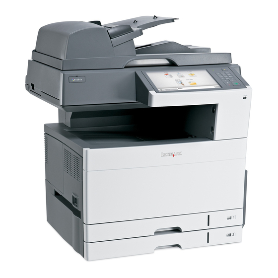
Page 20: Printer Configurations
If you purchased a multifunction printer (MFP) that scans, copies, and faxes, you may need additional furniture. For more information, see www.lexmark.com/multifunctionprinters. ADF input ADF output bin... -
Page 21: Options And Features
7541-03x Options and features Lexmark X925 printers support only Lexmark X925 paper-handling options. These options are not compatible with any other Lexmark printer. Some of the following options are not available in every country or region. Available internal options •... -
Page 22: Print Engine Specifications
7541-03x Print engine specifications Power specifications Average nominal power requirements for the base printer configuration. (Power levels are shown in watts.) Printing states Power Sleep Mode Hibernate Mode Ready Mode 105W Continuous printing 620W Electrical specifications Low-voltage models • 100 to 127 V ac at 50 to 60 hertz (Hz) nominal •... -
Page 23: Acoustics
7541-03x Acoustics All measurements are made in accordance with ISO 7779 and conform with ISO 9296. 1 meter average sound pressure Declared sound power level Status Bels Idle (Standby) 37 dBA Simplex printing 53 dBA Duplex printing 54 dBA Quiet Mode printing (Mono) 54 dBA Quiet Mode printing (Color) 54 dBA... -
Page 24: Performance
7541-03x Performance The X925 printers support up to 30 ppm (Letter) and 30 ppm (A4) maximum print speeds. Actual performance depends on: • Interface to host (parallel, serial, USB or network) • Host system and application • Complexity and content of the page •... -
Page 25: Media Types
7541-03x Optional Multipurpose Paper size Dimensions Tray 1 Tray 2 550-sheet Duplex unit feeder tray Executive 184 x 267 mm (7.3 x 10.5 in.) Oficio 216 x340 mm (8.5 x 13.4 in>) Folio 216 x 330 mm (8.5 x 13 in.) Statement 140 x 216 mm (5.5 x8.5 in.) -
Page 26: Media Weights
7541-03x Media weights Subsystem Size Type Weight Tray 1 All sizes supported Xerographic Long Grain 16lb to 34lb (60g/m2 to 128g/m2) by engine. and Bond Tray2 and Short Grain 16lb to 34lb (60g/m2 to 128g/m2) Excluding banner optional Recycled Long Grain 20lb to 34lb (75g/m2 to 128g/m2) drawers Short Grain... -
Page 27: Media Guidelines
Paper characteristics The following paper characteristics affect print quality and reliability. Consider these characteristics when evaluating new paper stock. For detailed information, see the Card Stock & Label Guide available on the Lexmark Web site at http:// support.lexmark.com. Weight The printer can automatically feed paper weights from 60 to 220 g/m (16 to 58 lb bond) grain long. -
Page 28: Unacceptable Paper
7541-03x Moisture content The amount of moisture in the paper affects both print quality and the ability of the printer to feed the paper properly. Leave the paper in its original wrapper until it is time to use it. This limits the exposure of the paper to moisture changes that can degrade its performance. -
Page 29: Scan Fax And Copy Specifications
7541-03x Scan fax and copy specifications General specifications Processor Speed and type 1GHZ, IBM Memory Standard 512 MB (Max 1.5 GB) Optional memory 256 MB, 512 MB and 1024 MB DDR SODIMM Optional flash memory 256 MB Hard drive 160 GB or higher Connections Standard Gigabit ethernet and USB... -
Page 30: Fax Features
7541-03x Fax features Feature Notes Fax preservation Faxes are preserved over power cycle Color fax Enable color scans Auto convert color to mono fax Enable color fax receive: • When on, the sending device transmits in color and the receiving device prints in grayscale. •... -
Page 31: Scanner Specifications
7541-03x Feature Notes Sound control Ringer volume Speaker volume Speaker mode—On, On until connected, Off Fax server Fax server mode will send the scanned fax job to the fax server as an email, where it will then be sent to the receiver. The device should be tested for configurability and compatibility with the deserved third fax server product (for example, Biscom, Equisys-ZetaFax, OMTool, Captaris-RightFax, or Tobit- Faxware). -
Page 32: Mfp Scan Speed
7541-03x MFP scan speed Simplex Duplex Media size Mono Color Mono Color Letter (plain A4 (plain) Note: Scan performance is measured as 150 dpi 1-bit for mono and 150 depi 24-bit for color. 1-14 Service Manual... -
Page 33: Tools Required For Service
7541-03x Tools required for service Flat-blade screwdrivers, various sizes #1 Phillips screwdriver, magnetic #2 Phillips screwdriver, magnetic #2 Phillips screwdriver, magnetic short-blade 7/32 inch (5.5 mm) open-end wrench 7.0 mm nut driver Needlenose pliers Diagonal side cutters Spring hook Feeler gauges Analog or digital multimeter Parallel wrap plug 1319128 Twinax/serial debug cable 1381963... -
Page 34: Acronyms
7541-03x Acronyms Alternating Current Autocompensator Mechanism (or paper feed) Automatic document feeder Analog front end Automatic Paper Size ASIC Application Specific Integrated Circuit BLDC Brushless DC Motor Black Only Retract Belt up down Cyan Counter clockwise Command Descriptor Blocks CMYK Cyan yellow magenta black Central processing unit Cyclic redundancy check... - Page 35 LASER Light amplification by stimulated emission of radiation Liquid crystal display Liquid Crystal Module Laser Diode Light emitting diode Long edge feed Lexmark Embedded Solution (applications) Low Voltage LVPS Low voltage power supply Magenta Megabyte Motor Driver Control Message handling...
- Page 36 7541-03x Short edge feed Solenoid SRAM Static random access memory Toner Add Roll Toner Patch Sensing Tandem Tray Module TVOC Total Volatile Organic Compound Universally Adjustable Tray Used Parts Return Universal Serial Bus Volts V ac Volts alternating current V dc Volts direct current Volt Ohmmeter Vacuum Transport Belt...
-
Page 37: Diagnostic Information
7541-03x 2. Diagnostic information Start CAUTION Unplug power cord from the electrical outlet before you connect or disconnect any cable or electronic board or assembly for personal safety and to prevent damage to the printer. Disconnect any connections between the printer and PCs/peripherals. CAUTION If the printer is kept on, never touch the conductive parts while it is not specifically required. -
Page 38: Flatbed / Icc Card Nvram
Flatbed / ICC card NVRAM The flatbed ICC card contains NVRAM. Do not use an ICC card from another X925 printer. Using an ICC card or complete flatbed assembly from another machine will result in a 950.10 NVRAM mismatch error. -
Page 39: Por (Power-On Reset) Sequence
7541-03x POR (Power-On Reset) sequence The following is an example of the events that occur during the POR sequence for the base machine with no paper handling options installed. Power the machine on. Power supply fan rotates. Splash screen with progress bar displayed. Printer controller initialized. -
Page 40: Print Quality Issues
7541-03x Print quality issues Note: This symptom may require replacement of one or more CRUs (Customer Replaceable Units) designated as supplies or maintenance items, which are the responsibility of the customer. With the customer's permission, you may need to install a developer (toner) cartridge or photoconductor unit. Service tip: Before troubleshooting any print quality problems, do the following: Print a menu settings page, and then check the life status of all supplies. -
Page 41: One Color Missing
7541-03x One color missing Step Action and questions Are the imaging units (photoconductors) properly Go to step 2. Reinstall the installed? imaging units. Is the photoconductor lock door properly closed on Go to step 3. Open and close both sides? photoconductor lock door ensuring that t is... -
Page 42: Lowered Print Density
7541-03x Lowered print density Step Action and questions Check the paper for moisture. Is the paper moist? Replace the Go to step 2. paper. Check the LED printhead for dirt. Is the printhead dirty? Go to step 3. Go to step 4. Clean the print head with a lint free cloth. -
Page 43: Partial Dirt
7541-03x Partial dirt Step Action and questions Is there toner attached to the developer roll, especially Replace the Go to step 2. the lower part of the roll. imaging unit. Check the transfer belt for defects or foreign matter Remove the dirt Go to step3 such as dirt. -
Page 44: Unprinted Spots
7541-03x Unprinted spots Step Action and questions Check the paper in the tray for moisture. Is the paper Replace the Go to step 2. moist? paper in the tray. Check the LED print head for moisture on the imaging Wipe the LED Go to step 3. -
Page 45: Black Page
7541-03x Black page Step Action and questions Inspect the contact points for the imaging unit and the Go to step 3 Go to step 2 printer. Are they clean and free of debris? Clean the contacts. Did this fix the issue? Problem resolved Go to step 3. -
Page 46: Stain On Back Of Page
7541-03x Stain on back of page Step Action and questions Check for dirt on the transfer belt. Is there dirt on the Clean the transfer belt? transfer belt with a lint free cloth. Check for dirt along the paper path. Is there dirt on the Clean any dirty paper path? paper path... -
Page 47: Adf & Scanner Print Quality
7541-03x ADF & scanner print quality Note: Get a printout as a base, and then follow the symptom table to identify the possible failing FRU. Image quality symptoms: • Dark print — “Dark image quality (using ADF or Scanner)” on page 2-11. -
Page 48: Vertical Lines (Process Direction Using The Adf)
7541-03x Vertical lines (process direction using the ADF) Step Check Check the small platen glass on the scanner unit Clean or replace Go to step 2. assembly. the scanner platen glass Is the large and small platen glass contaminated or cover. - Page 49 7541-03x Step Check Perform a print test using the scanner CCD assembly. Replace the Problem solved. scanner CCD Does the error continue? assembly. Go to “CCD chassis” on page 4-124. Perform a print test using the flatbed scanner assembly. Replace the ICC Problem solved.
-
Page 50: Skew (Using Adf)
7541-03x Skew (using ADF) The printed image is not paralleled with both sides of the media. Step Check Check printer installation placement. Go to step 2. Correct the installation Check the installation surface for irregularities. placement. Check for damaged printer caster. Is the setup surface normal? Properly load document into the ADF unit assembly and Go to step 3. -
Page 51: Media Damage (Using Adf)
7541-03x Media damage (using ADF) Step Check Properly load document into the ADF unit assembly and Go to step 2. Problem solved. ensure all guides are set correctly. Re-print the defective image. Does the error continue? Check for obstructions in the area of the media feed Go to step 3. -
Page 52: Black Page From Scanner
7541-03x Black page from scanner Step Questions / actions Print a menu page, or a page from the host. See Go to “Black page” Go to step 2. Is the page black? on page 2-9. Are the CCD ribbon cables properly Go to step 4 Go to step 3. -
Page 53: Paper Jams
7541-03x Paper jams User primary Location Explanation message 283.05 Scan Sensor Jams To resolve scanner jam issues, see “Clearing and resolving scanner jams” on page 2-29. 290.11 Scanner ADF Cover Open Jam 283.01 Scanner Static Jam - Scan Sensor Jams 280.06 Paper Missing 285.05... -
Page 54: Clearing And Troubleshooting Paper Jams
7541-03x Clearing and troubleshooting paper jams 200 paper jam Open the right side cover. Pull the paper up and out to remove it from the paper path. Note: Make sure all paper fragments are removed. If the page is in the fuser, the fuser nip release lever should be lowered. -
Page 55: Paper Jam
7541-03x Remove the jammed paper. Close the right cover. Press Continue, jam cleared. 203 paper jam Grasp any jammed paper that is visible in the exit bin and gently pull it out. Note: Make sure all paper fragments are removed. If the page is in the fuser, the fuser nip release lever should be lowered. -
Page 56: Paper Jam
7541-03x 230 paper jam Open the right cover. Lift the duplexing unit mechanism away from the cover. Remove any jammed paper. Lower the mechanism. Close the right cover. Press Continue, jam cleared. 2-20 Service Manual... -
Page 57: Paper Jam
7541-03x 231-39 paper jam Open the right cover. Lift the duplexing unit mechanism away from the cover. Remove any jammed paper. Lower the mechanism. Close the right cover. Press Continue, jam cleared. 2-21 Diagnostic information... -
Page 58: 24X Paper Jam
7541-03x 24x paper jam Jam in tray 1 Open the right cover and pull any jammed pages out. Open Tray 1, ad pull the jammed pages up and out. Close Tray 1. Press Continue, jam cleared. Jam in the optional trays Open the side affected tray’s access door and remove the jammed pages. -
Page 59: Paper Jam
7541-03x Open the affected tray and remove the jammed pages. Close the tray. Press Continue, jam cleared. 250 paper jam Remove the jammed pages from the multipurpose feeder. Load paper into the multipurpose feeder. Press Continue, jam cleared. 2-23 Diagnostic information... -
Page 60: Duplex Unit Service Check
7541-03x Duplex unit service check Action Feed roller belts Check for wear or damage to the feed roller belts. Replace as necessary. • Duplex clutch Check the clutch cable for proper connection to CN13 on the engine board. If it is properly connected, replace the clutch. If this doesn't fix the problem, replace the engine board. - Page 61 7541-03x Paper has stopped at the registration roller or has not reached the fuser (Paper jams 200, 250, 24x). Action • Registration roller Check these parts for wear or damage. Replace as necessary. Be clutch sure all guide surfaces in the paper path are free of dirt. •...
- Page 62 7541-03x Paper has entered the duplex unit (Paper jam 230, 231-9). Action Feed rollers Check for wear or damage to feed rollers and belts. Belts Duplex unit Be sure the duplex unit is properly installed and that all connections on the engine board (CN 28, 29, 13, 14) are correct. •...
-
Page 63: Paperfeed Unit Service Check
7541-03x Paperfeed unit service check Note: These tests can also be performed on the expansion paper-feed units. Action Door open interlock switch • Turn the printer on. • Open the door. • Check the operator panel for “Close Door” message. Paper tray level motor •... -
Page 64: Mpf Service Check
7541-03x Action Relay sensor • Bypass the turn guide door open sensor*. • Turn the printer on while holding down the paper relay sensor. - If the operator panel does not display “Paper Jam”, check for a dirty paper relay sensor. - If the paper relay sensor is clean, or the actuator for the paper relay sensor is broken, replace the sensor. -
Page 65: Clearing And Resolving Scanner Jams
7541-03x Clearing and resolving scanner jams Note: Before performing the ADF jam service procedures, perform the following steps: Remove all documents from the ADF input tray. Open the ADF cover. Gently remove the jammed paper from the ADF. Note: Make sure all paper fragments are removed. 280.06 Paper missing Step Action and questions... -
Page 66: Scanner Static Jam - Scan Sensor Jam
7541-03x Step Action and questions Check the ADF cable for continuity. Is there Go to step 16. Go to step 15. continuity? Replace the ADF cable. Did this fix the Problem resolved Go to step 16. problem? Replace the ADF relay board. Did this fix the Problem resolved Go to step 17.‘... -
Page 67: Scan Sensor Jam
7541-03x Step Action and questions Replace the ICC board. Did this fix the issue? Problem resolved Replace the RIP board. See “RIP board removal” on page 4-73. 283.05 Scan sensor jam Step Action and questions Remove the paper from the ADF. Did this resolve the Problem resolved Go to step 2. -
Page 68: Scanner Adf Eject Jam
7541-03x 285.05 Scanner ADF eject jam Step Action and questions Remove the paper from the ADF. Did this resolve the Problem resolved Go to step 2. problem? Remove the ADF main feed unit, and inspect the Go to step 6. Go to step 3. -
Page 69: Scanner Adf Cover Open Jam
7541-03x 290.11 Scanner ADF cover open jam Note: In addition to the steps below, See “ADF cover open service check” on page 2-77. Step Action and questions Open the ADF top cover and check the cover Go to step 4. Go to step 2. - Page 70 7541-03x Step Action and questions Replace the ICC board. Did this fix the issue? Problem resolved Replace the RIP board. See “RIP board removal” on page 4-73. 2-34 Service Manual...
-
Page 71: Flatbed Cover Open
7541-03x 291.06 Flatbed cover open Step Action and questions POR the MFP. Does the error re-occur. Go to step 2. Problem solved Check the sensor (FB Cover open) for proper Go to step 4. Go to step 3 operation. 1. Enter the Diagnostics Menu. 2. -
Page 72: Adf Paper Jam Service Check
7541-03x ADF paper jam service check Note: This service check should be used if the paper feeds and jams in the ADF. If the paper is not feeding into the ADF see “280.06 Paper missing” on page 2-29. If the paper fails to eject from the ADF see Step Questions / actions If the ADF is multi-feeding, check for dirt on... - Page 73 7541-03x Step Questions / actions Replace the ICC board. Did this fix the Problem resolved Replace the RIP board. See issue? “RIP board removal” on page 4-73. 2-37 Diagnostic information...
-
Page 74: Error Codes
7541-03x Error codes In addition to the 1xx and 9xx error codes, this device has displays a symptom where the device shuts down repeatedly. The main symptom of this error is the switch going to the off position automatically when the device PORs. -
Page 75: Abnormal Eeprom
7541-03x 9xx error codes Action 941.01 SDRAM R/W error “941.01 SDRAM R/W error” on page 2-62 900.xx Unrecoverable RIP “900.xx System software error” on page 2-60. software error / illegal trap 910.xx Unrecoverable engine Turn off printer for 10 seconds and restart. If error re-occurs, replace RIP firmware error board. - Page 76 7541-03x 8xx scanner error Description Action codes 840.01 The scanner has been Enter the configuration mode to re- manually disabled enable the scanner. 840.02 The scanner has Enter the configuration mode to re- automatically been disabled enable the scanner. by the controller 840.03 Scanner cable unplugged Check the scanner cables for proper...
-
Page 77: Fax T30 Log Error Codes
7541-03x Fax T30 log error codes Fax error log codes Error code Description Action No error occurred during fax No action needed transmission Error occurred when transmitting • Check line quality. • Select a lower ‘Max Speed’. training. • value under Fax Send settings •... - Page 78 7541-03x Fax error log codes (Continued) Error code Description Action T5 Timeout occurred when transmitting • Check line quality. image data to remote fax device. • Adjust ‘Transmit Level’. • Select a lower ‘Max Speed’value under Fax Send settings. Too many errors when transmitting in •...
- Page 79 7541-03x Fax error log codes (Continued) Error code Description Action Failure to transmit training successfully • Select a lower “Max Speed” under Fax in V17, V29 terminal modulation Send settings. schemes. • Adjust the “Transmit Level”. • Check line quality. Failure to transmit training successfully •...
- Page 80 7541-03x Fax error log codes (Continued) Error code Description Action Modem detected a digital line Verify the MFP is connected to an analog connection. line. See“Faxes fail to transmit” on page 2-78. Phone line was disconnected Restore phone line connection. Received request for unsupported No action needed.
-
Page 81: Service Checks
7541-03x Service checks 111.01 Black printhead error Step Action and questions Is the ribbon cable connecting CN4 on the printhead Go to step 2 Properly connect controller board to the black LED head securely the ribbon cable connected? Replace the ribbon cable. Does this fix the problem? Problem fixed Go to step 3. -
Page 82: Thermistor 1 Error
7541-03x 121.01 Thermistor 1 error Note: If the error is 121.05., the fuser is at the end of life. Step Action and questions Is the fuser properly installed? Make sure that it is Go to step 2. Reinstall the properly seated. fuser. -
Page 83: Thermistor 3 3 Error
7541-03x 121.03 Thermistor 3 3 error Note: If the error is 121.05., the fuser is at the end of life. Step Action and questions Is the fuser properly installed? Make sure that it is Go to step 2. Reinstall the properly seated. -
Page 84: Fuser - Fuser Heater Error
7541-03x 121.05 Fuser - fuser heater error Step Action and questions Is the fuser installed and seated properly? Go to step 2. Properly install the fuser. Are CN02 and CN04 on the LVPS, and CN16 on the Go to step 3. Properly connect printhead control board properly connected? all the cables. -
Page 85: High Voltage Power Supply Error
7541-03x 130.xx High voltage power supply error Step Action and questions Check CN11 on the printhead controller board, and Go to step 2 Properly connect CN01 on the HVPS for proper connectivity. Are the the connections. connection properly connected? Check the HVPS - printhead controller cable for Go to step 4. -
Page 86: Abnormal Theta Sensor
7541-03x 132.xx Abnormal theta sensor Step Action and questions Is the reference pattern for the color plane alignment Go to step 4. Go to step 2. printing properly on the transfer belt? Did all the colors print on the test pattern? Go to step 4. -
Page 87: Drive Motor Error
7541-03x 140 Drive motor error Step Action and questions Are CN 17, 18, 19, and 29 on the engine controller Go to step 2. Connect the board properly connected? cables to the board. Are the cables properly connected to the drive motors? Go to step 3. -
Page 88: Tray1Error
7541-03x 146.01 Tray1error Note: This is the service check for the standard paper tray. Step Action and questions Check the cable connecting the paper tray lift motor to Go to step 3 Go to step 2 CN 6 on the engine board. Is the cable properly connected at both ends? Connect the cable properly at both ends. -
Page 89: Tray 4 Error
7541-03x Step Action and questions Replace the paper full sensor cable. Did this fix the Problem solved. Go to step 12. problem? Replace the paper full sensor. Did this fix the issue? Problem solved. Go to step 13. Replace the expansion paper feeder controller board. Problem solved. -
Page 90: Tray 5 Error
7541-03x 146.05 Tray 5 error Note: This is the third expansion tray. Step Action and questions Check CN 121 on the second expansion paper Go to step 3. Go to step 2. feeder’s expansion feeder controller board for proper connectivity. Is it properly connected? Reconnect the cable to CN 121.Did this fix the Problem Go to step 3. -
Page 91: Power Supply Unit Fan Error
7541-03x 172.01 - Power supply unit fan error Step Questions/actions Is there anything obstructing the fan’s movement? Clear the Go to step 2. obstruction. Check connector CN22 on the MDCONT board, and Go to step 3 Reconnect the CN04 and CN05 on the LVPS. Are they properly connectors. -
Page 92: Service Check
7541-03x 840.03 service check Step Questions/actions • Check the 8 and 30 pin ribbon cables connecting Reseat the cable Go to step 2. the CCD to the ICC card for proper connection. • Check the ribbon cable connecting the RIP board to the ICC card for proper connection. -
Page 93: Delayed Interrupt Detected
7541-03x 841.02 Delayed interrupt detected Step Questions/actions POR the device a few times. Did the error re-occur? Go to step 2. Problem resolved Update the firmware. Before doing so, contact your Problem resolved Go to step 3. second level support for the correct level firmware to flash the device with. -
Page 94: Scanner Did Not Initiate Scan
7541-03x 841.06 Scanner did not initiate scan Step Questions/actions Check the cables connecting the RIP board to the Go to step 2. Go to step 3. scanner for damage. Is there any visible damage? Replace the faulty cables. Did this fix the problem? Problem resolved Go to step 3. -
Page 95: Carriage Home
7541-03x 843.00 Carriage Home Step Questions/actions POR the device.Did the error re-occur? Go to step 2. Problem resolved Check all the connections from the ICC card to the Go to step 3 Go to step 4. CCD carriage, and RIP board to ICC card. Are the cables properly connected? Properly connect all the cables. -
Page 96: System Software Error
Note: Before troubleshooting, determine the operating system used when the error occured. If possible determine whether a PostScript or PCL file was sent to the device when the error occured. Ask the customer which Lexmark Solutions applications are installed on the device. Step Action and questions POR the device. - Page 97 Reinstall the memory, and send a print job to the Go to step 15. Go to step 16. device. Does the 900.xx error reoccur? Install a Lexmark recommended memory option. Send Go to step 31. Problem a print job to the device. resolved.
-
Page 98: Sdram R/W Error
7541-03x Step Action and questions Are there any more ISP options to install? Go to step 27 Problem resolved. Install the next ISP option. Restart the device. Go to step 29. Go to step 28. Does the 900.xx error reoccur? Run a job to test the option. -
Page 99: Cpu Error
7541-03x Step Action and questions Re connect the cables. Did this fix the problem Problem resolved Go to step 3. Check the cables for continuity. Is there continuity? Go to step 5. Go to step 4. Replace the cables. Did this fix the issue? Problem resolved Go to step 5. -
Page 100: 950.29-Eprom Mismatch Failure
7541-03x 950.00–950.29—EPROM mismatch failure Warning: When replacing any of the following components, replace only one component at a time or the printer will be rendered inoperable: • System board • Flatbed scanner assembly • Scanner interface card Replace the required component, bring the printer up in Diagnostics mode (see “Diagnostics mode”... -
Page 101: Service Invalid Firmware Error
7541-03x 959.xx Service invalid firmware error Step Action and questions POR the printer a few times. Does the problem re- Go to step 2. Problem occur? resolved. Put the machine into recovery mode and update the Problem resolved Go to step 3. firmware. -
Page 102: User Attendance Messages
7541-03x User attendance messages User prompts Error code Action Adjusting color Wait until the process is completed. Change <src><custom This message allows the user to override the source for the remainder of a job. The page will type name> be printed as it is formatted on the paper installed in the tray. This may cause clipping. No <orientation>... - Page 103 7541-03x Error code Action Close Tray Door Close Front Door Close the front door securely. Disk Corrupted, The printer has attempted a disk recovery and cannot repair the disk. The disk must be Reformat? formatted to use. Warning: All files stored on the disk will be lost. Held Jobs May Not Be The printer has attempted to restore Held jobs, but not all were restored.
- Page 104 7541-03x Error code Action Load Manual <size> If paper loaded is in the manual feeder, the job continues. If paper is not in the feeder, pressing Select indicates to the printer it should search for a source with the proper size. Additional messages may include: •...
-
Page 105: User Attendance Messages (0-99)
7541-03x Error code Action USB Drive Error This is displayed when an error on the USB drive occurs. The user is instructed to remove and reinsert the drive. Disk Problem Error reading a disk. Disk is improperly formatted. Additional messages include: •... - Page 106 7541-03x Error code Action 35 Insufficient memory • Select Continue to disable Resource Save and continue printing. to support Resource • To enable Resource Save after receiving this message: Save feature - Make sure the link buffers are set to Auto, then exit the menus to activate the link buffer changes.
- Page 107 7541-03x Error code Action 51 Defective Flash • Select Continue to clear the message and continue printing. • Install different flash memory before downloading any resources to flash. • If this does not fix the problem, replace the RIP board. See “RIP board removal”...
- Page 108 7541-03x Error code Action 56 USB Port <x> • Select Continue to clear the message. Disabled The printer discards any data received through the USB port. • Make sure the USB Buffer menu item is not set to Disabled. • If this does not fix the problem, replace the PCI card. 56 Standard USB Port •...
- Page 109 7541-03x Error code Action 80 Fuser Near Life • Select Continue to clear the message and continue printing. Warning • Show Me, View Supplies, and Tell Me More displays additional information. • Order a replacement fuser. When print quality is reduced, install the new fuser using the instruction sheet that comes with the replacement fuser.
- Page 110 7541-03x Error code Action 84 Replace <color> • Replace the specified photoconductor unit using the instruction sheet that comes with the Photoconductor replacement specified photoconductor unit. • If the problem persists, reset the supplies in the supplies menu. 84 <color> PC Unit “Imaging unit (photo developer) missing service check”...
-
Page 111: Other Symptoms
“Transfer belt up down check” on page 2-93. Transparencies curl excessively. Make sure you’re using the recommended Lexmark transparencies. Also be sure the paper delivery is set to the rear exit. The printer seems slow to print. If you set the Paper Type to Transparency or Card Stock, the printer increases the fuser temperature and slows printing to improve the print quality. -
Page 112: Scan / Copy
7541-03x Symptom Action Evenly spaced marks on the Go to “Transfer belt up down check” on page 2-93. paper, or a single mark in the same place on every page. Poor fusing. Go to “121.05 Fuser - fuser heater error” on page 2-48. -
Page 113: Adf Cover Open Service Check
7541-03x ADF cover open service check Step Questions / actions Is the ADF cover properly closed Go to step 3. Go to step 2. Close the ADF cover. Issue resolved Go to step 3. Does the problem go away? Perform the ADF cover open sensor test. Go to step 4 Go to step 8. -
Page 114: Fax Symptoms
7541-03x Fax symptoms Faxes fail to transmit Note: Before performing this service check, verify that the correct country code for the MFP is selected. This setting must match the country in which the MFP is used to transmit and receive faxes. If the setting is wrong, the modem settings can be changed in the Fax/SE menu. - Page 115 7541-03x Step Questions / actions Press **411 to enter the Fax/SE Menu. Problem resolved. Go to step 15. Select “Print Logs”. Print the T30 transmission log. Check the error being reported with the fax error code table. See “Fax T30 log error codes” on page 2-41.
-
Page 116: Fax Reception Fails
7541-03x Fax reception fails Step Questions / actions Is the phone line properly connected to the Go to step 3. Go to step 2. modem card and the wall jack? Properly connect the phone line to the Problem resolved. Go to step 3. modem card and wall jack. - Page 117 7541-03x Step Questions / actions Disable Block No Name Fax user setting. Problem resolved. Go to step 17. Did this fix the issue? Go to the Administrator menu. Enter the Fax Go to step 18. Go to step 19. settings - Analog Fax Settings submenu. Verify the remote device number is not in the Banned Fax List user setting.
-
Page 118: Escalating A Fax Issue To Second-Level Support
7541-03x Escalating a fax issue to second-level support Before contacting the second-level support, go to the SE menu on the MFP.and generate a Fax error file. This file contains machine settings information and debug information that will help second-level support determine the cause of a failure. -
Page 119: Words On Fax Are Stretched
7541-03x Words on fax are stretched The sending machine had a temporary jam. Incoming fax has blank spaces or poor quality The sending fax machine may be faulty. The sending fax machine may have a dirty document glass. A noisy phone line can cause errors. Check the MFP print quality by making a copy. -
Page 120: Other Service Checks
Have the network administrator verify that the device is using the correct SSID, and wireless security protocols. For more network troubleshooting information, consult the Lexmark Network Setup Guide. - Page 121 7541-03x Step Questions / actions Is the device physically connected (ethernet Go to step 13. Go to step15. cable) to the network? Try using a different ethernet cable. Problem resolved Go to step 14. Did this remedy the situation? Have the network administrator check the Replace the controller Contact the network network drop for activity.
-
Page 122: Option Card Service Check
7541-03x Option card service check Option card service check Action Option cards Card Controller board Remove all the option cards from the device. Option card connection Install each card individually. Restart the MFP after each card is installed. cable Remove the card and repeat the previous step with a different card till all cards are Warning: Do not checked. -
Page 123: Operator Panel Service Check
7541-03x Operator panel service check Display functions but the keyboard doesn’t work properly Step Action and questions Check the cable connection between the RIP and the Go to step 3. Go to step 2. UICC, and check the connection from the UICC to the display. -
Page 124: Insert Tray Service Check
7541-03x Step Action and questions Check connector J9 on the RIP board for the following Go to step 9. Go to step 8. voltages and grounds. Pins 2, 9, 15, 20, 21 - GND Pins 10, 16, 17, 18, 23 - +5V Do the voltages and ground readings approximately match the table? Replace the RIP board. -
Page 125: Paper Skew Service Check
7541-03x Paper skew service check Step Action and questions Are the paper guides in the paper trays and MPF tray Go to step 4. Go to step 3. in there proper position. Adjust all the paper guides. Did this fix the problem? Problem solved. -
Page 126: Option Card Service Check
7541-03x Option card service check Step Action and questions Remove all the cards, and POR the machine. Does the Go to step 3. Go to step2. printer work normally? Replace the RIP. Does the printer work normally? Go to step 3. Contact your second level support. -
Page 127: Hard Disk Option
7541-03x Hard disk option Service Tip: The 5041-030 printers support one hard disk option. Be sure only one hard disk option is installed. Be sure the hard disk and the hard disk board are correctly installed. Run the “Quick Disk Test” on page 3-23 from the Device Test on the Diagnostic Menu. -
Page 128: Power Supply (Dead Machine) Service Check
7541-03x Power supply (Dead machine) service check Note: Before proceeding, make sure that this is not an issue with the display. Turn the machine on. If the machine’s fans, and motors start up, it could be an issue with the display. Step Action and questions Is the power cord connected to the printer and the wall... -
Page 129: Printhead Service Check
7541-03x Printhead service check Step Action and questions Check the LED for any dirt or toner that may distort the Go to step 2. Go to step 3. image. Is the LED dirty? Clean the LED. Did this fix the problem? Problem solved Go to step 3. -
Page 130: Unable To Print From Usb Thumb Drive Service Check
7541-03x Unable to print from USB thumb drive service check Step Action and questions Try a different thumb drive. Does that drive work? Problem solved Go to step 2. Verify that the USB cable is properly connected to the Go to step 4. Go to step 3. -
Page 131: Wrong Paper Size Service Check - Tray1
7541-03x Wrong paper size service check - tray1 Step Action and questions Check the size indicator on the front of the tray. Is it set Go to step 3. Go to step 2. to the correct size? Set the indicator to the correct size. Did this fix the Problem solved Go to step 3. -
Page 132: Paper In Adf Size Service Check
7541-03x Paper in ADF size service check Step Action and questions Check the sensors (ADF long, width 1,and width 2) for Go to step 7. Go to step2. proper operation. 1. Enter the Diagnostics Menu. 2. Touch SCANNER TESTS. 3. Touch Sensor Tests. 4. -
Page 133: Diagnostic Aids
7541-03x 3. Diagnostic aids This chapter provides basic information to help you navigate the printer menus and explains the tests and procedures used to identify printer failures and verify repairs have corrected the problem. Understanding the operator panel and menus Operator panel (need new art) @ ! . -
Page 134: Understanding The Home Screen
7541-03x Understanding the home screen Buttons appearing on the home screen may vary depending on home screen customization settings. Possible buttons and icons on the home screen Item Description Copy Opens the Copy menu E-mail Opens the E-mail menu Scan Opens the Scan menu Opens the Fax menu Opens the administrative menus when Ready appears on the display... -
Page 135: Using The Touch Screen
7541-03x Item Description Unlock Device This button appears when the printer is locked. The operator panel (not pictured) buttons and shortcuts cannot be used while this appears. Touching this button opens a PIN entry screen. Enter the correct PIN to unlock the printer control panel. - Page 136 7541-03x Button Function Right scroll increase Increases a value Left scroll decrease Decreases a value Returns to the home screen Home Exit Exits from the current screen to the home screen Tips Opens context-sensitive Help on the touch screen Other touch-screen buttons Icon Function Accept...
- Page 137 7541-03x Icon Function Selected radio button Indicates a selection Index Displays information about the key functions of the printer, including instructions on how to operate it Search Lets you search for files and menus Indicates a warning or error condition Warning Diagnostic aids...
-
Page 138: Administrative Menus
7541-03x Administrative menus See the menu map for a brief overview of the printer menus available from the operator panel. Select a menu or menu item for more details. Reports Supplies Menu Network/Ports Paper Menu Menu Settings Page Replace Supply Active NIC Device Statistics Default Source... -
Page 139: Accessing The Service Menus
7541-03x Accessing the service menus There are different test menus that can be accessed during POR to identify problems with the printer. Diagnostics menu 1. Turn off the printer. The Diagnostics menu group contains the settings and 2. Press and hold 3 and 6. operations used while manufacturing and servicing the printer. - Page 140 7541-03x Recovery mode 1. Turn off the printer. This mode will allow the printer to boot from a secondary set of 2. Press and hold 2, 7,and 8. instructions to allow a code flash 3. Turn on the printer. to the printer. Code can be 4.
-
Page 141: Configuration Menu
7541-03x Configuration Menu The Configuration menu contains a set of menus, settings, and operations which are infrequently used by a user. Generally, the options made available in this menu are used to configure a printer for operation. An asterisk (*) in the value list in the following menus indicates the default value. Entering Config Menu To enter the Configuration Menu: Turn off the printer. -
Page 142: Reset Separator Roll And Pick Assembly Counter
7541-03x Configuration Menu Auto Align Adj “Auto Align Adj” on page 3-13 Color Alignment “Color Alignment” on page 3-14 ADF Edge Erase “ADF Edge Erase” on page 3-14. FB Edge Erase “FB Edge Erase” on page 3-15. Scanner Manual Registration “Scanner Manual Registration”... -
Page 143: Reset Transfer Belt Counter
7541-03x Reset Transfer Belt Counter This menu item is used to reset the fuser counter for the print engine. Touch the menu item. A “Reset Fuser Counter” button is displayed. Touch that button to reset the counter. USB Scan to Local When set to Off, this setting tells the USB device driver to enumerate as a USB Simple device. -
Page 144: Tray Insert Message
7541-03x Tray Insert Message This setting determines how many seconds the panel will display the “Tray Insert” message after a user has inserted a tray into the printer. The values are 1 - 90 seconds. Select Tray Insert Message from the Configuration menu. Use the arrows to scroll to the desire value. -
Page 145: Energy Conserve
7541-03x Energy Conserve When Energy Conserve is on, the customer does not have access to disable the Sleep Mode function. When Energy Conserve is off, Disable appears as an additional menu item in the Sleep Mode menu. This setting only affects the values that are displayed in the Sleep Mode menu. -
Page 146: Color Alignment
7541-03x Color Alignment When you enter Color Alignment, the printer generates four alignment pages that are used to set the color alignment on the print engine. This needs to be run whenever a toner cartridge or imaging unit is installed on the print engine. -
Page 147: Fb Edge Erase
7541-03x FB Edge Erase The FB Edge Erase setting specifies, in millimeters, the size of a border around the scanned image that will be erased. For copies, the printed page will always have a at least a 2-mm no-print border. The larger of the 2-mm no-print border and the Edge Erase setting will be used in this situation. -
Page 148: Disk Encryption
7541-03x Disk Encryption This setting appears only if a hard disk is installed, the disk is not read only, and Disk Encryption is enabled. Warning: When the settings are changed, all data on the hard disk is deleted. Erase all information on Disks This setting performs a wipe of the printer hard disk, erasing all data. -
Page 149: Usb Speed
7541-03x USB Speed This setting determines the speed at which the USB port reads and writes data from flash drives. Auto is the default setting. Setting the USB Speed to Full disables the hi-speed capabilities of the port. USB PnP Use this menu item to toggle between USB 1.0 and 2.0. -
Page 150: Diagnostics Mode
7541-03x Diagnostics mode To run the printer diagnostic tests described in this chapter, put the printer in Diagnostics mode. Entering Diagnostics mode To enter the Diagnostics Mode: Turn off the printer. Press and hold 3 and 6. Turn on the printer. Hold the buttons until the splash screen appears. - Page 151 7541-03x HARDWARE TESTS Panel Test “Panel Test” on page 3-21 Button Test “Button Test” on page 3-21 DRAM Test “DRAM Test” on page 3-21 Serial 1 Wrap (if installed) “Serial Wrap Test” on page 3-22 USB HS Test Mode INPUT TRAY TESTS (if installed) Feed Test DEVICE TESTS (if installed) Quick Disk Test...
-
Page 152: Scanner Calibration
7541-03x SCANNER CALIBRATION Adjust Calibration Values This menu is used to manually adjust the scanner black levels to optimize printed text and images from scanned or copied originals. Use this menu to adjust the levels after you replace any of the following parts: –... -
Page 153: Print Quality Pages
7541-03x Print Quality Pages The print quality test consists of five pages. Pages one and two contain a mixture of graphics and text. The remainder of the pages only contain graphics. This test may be printed from either Configuration menu or the Diagnostics menu. To run the print quality pages from the Diagnostics menu, select PRINT TESTS and Print Quality Pages from the menu. -
Page 154: Serial Wrap Test
7541-03x Serial Wrap Test Use this test to check the operation of the Serial Port Hardware using a wrap plug. Each signal is tested. Note: this test is listed only if the serial option ISP card is installed. To run the Serial Wrap Test: Disconnect the serial interface cable, and install the wrap plug. -
Page 155: Usb Hs Test Mode
7541-03x USB HS Test Mode 1. From the Diagnostics menu, navigate to: HARDWARE TESTS > USB HS Test Mode 2. Select the desired Port. The test begins immediately for the Single Stop tests. 3. Select the desired Test. Ports Tests Port 0 Test J Port 1... -
Page 156: Flash Test
7541-03x Flash Test This test causes the file system to write and read data on the flash to test the flash. Warning: This test destroys all data on the flash because the flash is reformatted at the end of the test. Select Flash Test from DEVICE TESTS From the Diagnostics menu, navigate to: DEVICE TESTS >... -
Page 157: Page Counts
7541-03x PAGE COUNTS This menu lets you view the total page counts of the printer or the page counts broken down into color and mono pages printed. Unlike in previous printers, none of these values can be changed. Touch Back to return to the Diagnostics menu. Serial Number You can view the serial number. -
Page 158: Par 1 Strobe Adj
7541-03x Par 1 Strobe Adj Parallel Strobe Adjustment enables you to change the amount of time the strobe is sampled in order to determine if data is available on the parallel port. Increasing the value increases the amount of time by 50 ns per increment. -
Page 159: Print Log
7541-03x Print Log The Print Log menu item prints a detailed report of each event in the log. The first page of the event log contains a Printer Information section similar to what is printed on a Menu Setting Page. Printed at the top of each page is the model name and serial number to assist in tracking each page of a report to a specific printer. -
Page 160: Scanner Tests
7541-03x SCANNER TESTS Scanner Calibration Reset This option resets the scanner calibration values to factory default settings. This should be done after you replace the flatbed scanner unit. For more information, see “Calibrating the scanner” on page 4-205. Note: Be sure the scanner glass and backing material are clean before performing this test. ASIC Test This test initiates a scan of the scanner ASIC memory. -
Page 161: Theory Of Operation
7541-03x Theory of operation Printer engine Electrophotographic Process (EP Process) The method that all laser and LED printers use to print is called the electrophotographic process. These machines use differences in charge to manipulate and move toner from the toner cartridge to the printed page. Even though the basic EP process is the same for every laser and LED printer, the specifics for each printer are different. -
Page 162: Step 1: Charge
7541-03x Step 1: Charge During the charge step, voltage is sent from the high-voltage power supply to the charge roller (A) beside each of the four photoconductors. The charge roller is part of the photoconductor unit. The charge roller (A) puts a uniform negative charge over the entire surface of the photoconductor to prepare it for the LED. -
Page 163: Step 2: Expose
7541-03x Step 2: Expose During the expose step, the LED exposes the surface of each photoconductor (B) and writes an invisible image called a latent image or electrostatic image for each color. The LED actually discharges the surface only where the beam hits the photoconductor. This creates a difference in charge potential between the exposed area and the rest of the photoconductor surface. -
Page 164: Step 3: Develop
7541-03x Step 3: Develop Once the laser exposes the photoconductor, the high-voltage power supply sends charge to the developer roll (C). For each color, the toner cartridge engages the photoconductor so it is in contact with the surface. Because of the charge difference between the toner on the developer roller and the electrostatic image created by the laser, the toner will attract to the photoconductor only where the laser exposed the surface. -
Page 165: Step 4A: First Transfer
7541-03x Step 4a: First transfer When the latent images are developed on each Photoconductor, the high-voltage power supply sends voltage to the 1st Transfer Rollers inside the transfer belt unit. The charge difference between the developed toner image on the Photoconductor surface and the 1st Transfer Roller causes the images to transfer to the surface of the transfer belt for each color. -
Page 166: Step 4B: Second Transfer
7541-03x Step 4b: Second transfer Once the four planes of color are transferred to the transfer belt from the photoconductors, the image is carried towards the transfer roll. This transfer roll is mounted on the duplex unit. The paper passes between the transfer belt and transfer roll when the image on the belt reaches the second transfer area. -
Page 167: Step 5: Fuse
7541-03x Step 5: Fuse Once the image has been fully transferred to the media, the transfer roll helps move the paper into the fuser area. The fuser applies heat and pressure to the page to melt the tiny toner particles and bond them permanently to the media. -
Page 168: Step 6: Clean/Erase
7541-03x Step 6: Clean/Erase There are two main cleaning processes that take place during the EP Process. One process cleans the transfer belt, and the other cleans the photoconductors. Transfer Unit Clean Once the toner image on the transfer belt has been transferred to the page, the transfer belt rotates around and is cleaned by the cleaning blade. -
Page 169: Cleaning Blade
7541-03x Photoconductor Clean/Erase After each plane of color has been transferred to the transfer belt from the photoconductors, a cleaning blade scrapes the remaining toner from the surface of each photoconductor. This is the clean/erase process. Cleaning blade Now the photoconductor surface is prepared to begin the EP cycle once again. This cleaning/erasing cycle happens after each plane of color is transferred to the transfer belt. -
Page 170: Paper Path Components
7541-03x Paper path components Paper feed The standard paper feed sources consist of a multi-paper cassette (Tray 1), a standard paper cassette (Tray 2), and an MPF Tray. The paper feed system on the paper cassettes uses a separation roll/torque limiter to prevent multiple feeds. - Page 171 7541-03x Tray 2 and optional trays (3-5) Trays 2 through Tray 5 use a motorized lift mechanism to engage the media in the tray with the pickup roller. Tray 1 holds up to150 sheets of 20 lb. paper and the optional Trays (3-5) can hold up to 500 sheets of 20lb paper.
-
Page 172: Feeding Paper From A Tray
7541-03x Feeding paper from a tray The printer controller sends a signal to turn on the paper feed clutch; the pick roll grabs the top sheet of paper while the separator roll rotates backwards to prevent multiple sheets of paper from feeding. The paper moves to the feed roll and is fed into the paper path. -
Page 173: Feeding Paper From The Mpf
7541-03x Feeding paper from the MPF To start the paper feed, the printer controller sends a signal to turn on the MPF feed clutch; the paper feed motor starts turning to feed the top sheet of paper in the MPF tray one by one. Once the duplex exit/MPF detection lever senses the leading edge of the media at the duplex exit roller, it engages the duplex re-feed clutch to transport the sheet of paper into the paper path. - Page 174 7541-03x Paper registration As the media trips the Registration Sensor, it briefly stops at the Registration Rollers. Here, the leading edge is adjusted so it is parallel with the image on the Transfer Belt and synchronized with the Belt’s rotation. Next, the paper feed motor triggers the Registration Clutch to rotate the Registration Rollers to feed the paper toward the Transfer Belt and 2nd Transfer Roller.
- Page 175 7541-03x Duplexing If a page is two-sided, a signal is sent to the Printer Controller Board once the trailing edge of the paper passes the Fuser Exit Sensor. The leading edge of the paper partially feeds from the Exit Rolls and then reverses direction and feeds into the Duplex Unit.
-
Page 176: Scanner
7541-03x Scanner Duplex ADF The following illustration shows the paperpath, rollers and sensors used in the X925 duplex ADF. Affected CRU / FRU part Callout Part name catalog name ADF paper length and width sensors - photo reflect / Tray paper size sensor... - Page 177 7541-03x The X925 duplex ADF enables the user to create duplex scans automatically, eliminating the need to stop the scanning process to flip the media being duplicated over. The ADF uses a step motor, and a series of sensors to determine the media’s position in the paper path during the scan process.
- Page 178 7541-03x 11. The duplex gate is moved into position by a solenoid. After passing through the gate, the paper reaches the paper pass sensor. The paper pass sensor performs two tasks. It can determine whether a jam has taken place. The jam is triggered by the time it takes for the paper to pass through the sensor.
-
Page 179: Color Theory
7541-03x Color theory What is RGB color? Red, green, and blue light can be added together in various amounts to produce a large range of colors observed in nature. For example, red and green can be combined to create yellow. Televisions and computer monitors create colors in this manner. -
Page 180: My Color Transparencies Seem Dark When They Are Projected. Is There Anything I Can Do To Improve The Color
7541-03x My color transparencies seem dark when they are projected. Is there anything I can do to improve the color? This problem most commonly occurs when projecting transparencies with reflective overhead projectors. To obtain the highest projected color quality, transmissive overhead projectors are recommended. If a reflective projector must be used, then adjusting the Toner Darkness setting to 1, 2, or 3 will lighten the transparency. -
Page 181: What Are Detailed Color Samples And How Do I Access Them
7541-03x What are detailed Color Samples and how do I access them? Detailed Color Samples sets are available only through the Embedded Web Server of a network printer. A detailed Color Samples set contains a range of shades (displayed as colored boxes) that are similar to a user- defined RGB or CMYK value. - Page 182 7541-03x 3-50 Service Manual...
-
Page 183: Repair Information
7541-03x 4. Repair information Warning: Read the following before handling electronic parts. Handling ESD-sensitive parts Many electronic products use parts that are known to be sensitive to electrostatic discharge (ESD). To prevent damage to ESD-sensitive parts, use the following instructions in addition to all the usual precautions, such as turning off power before removing logic boards: •... -
Page 184: Flatbed / Icc Card Nvram
Flatbed / ICC card NVRAM The flatbed ICC card contains NVRAM. Do not use an ICC card from another X925 printer. Using an ICC card or complete flatbed assembly from another machine will result in a 950.10 NVRAM mismatch error. -
Page 185: Esf Solutions Backup
7541-03x If the above procedure fails, you must contact the technical support center for further instructions. eSF solutions backup If a technician needs to replace the RIP board, the steps below should be taken to backup the eSF solutions and settings: POR the printer into invalid engine code mode. -
Page 186: Removal Procedures
7541-03x Removal procedures CAUTION Remove the power cord from the electrical outlet before you connect or disconnect any cable or electronic board or assembly for personal safety and to prevent damage to the printer. Disconnect any connections between the printer and PCs/peripherals. Arrangement of removals in this chapter The removals in this chapter are arranged by area of printer. -
Page 187: Cover Removals
7541-03x Cover Removals RIP cover Remove the two screws securing the RIP cover to the RIP cage. Remove the RIP cover. Repair information... -
Page 188: Scanner Power Supply Access Cover
7541-03x Scanner power supply access cover Press the access cover inward at the arrow and pull back, removing the cover. Cord cover Remove the screw (A) securing the right side of the cord cover to the rear cover and scanner frame. Service Manual... -
Page 189: Rear Cover
7541-03x Remove the screw (B) securing the left side of the cord cover to the rear cover and scanner frame. Tilt the cord cover back and lift it up and away from the rear of the scanner. Rear cover Remove the cord cover. See “Cord cover”... - Page 190 7541-03x Remove the two screws (B) in the lower left corner. Remove the screw (C) in the lower left corner. Service Manual...
- Page 191 7541-03x Remove the screw (D) in the upper right corner. Remove the screw (E) in the top middle of the cover. Repair information...
- Page 192 7541-03x Remove the screw (F) in the upper left corner of the cover. Open the duplex unit and remove the one plastite screw that secures the cover to the side frame. Remove the option connector cover. Use the flatblade screwdriver to pry the rear cover away from the side cover at the main fan. Use a small flatblade screwdriver to release the tabs (G) that fasten the option connector cable to the rear cover.
-
Page 193: Front Op Panel Cover
7541-03x Front op panel cover Remove the one screw (A) on the front right side. Remove the two screws (B) on the on the inner left side of the cover. 4-11 Repair information... - Page 194 7541-03x Remove the two screws (C) on the under side of the cover. Pull the cover back. Disconnect the USB cable (D) from the cover. 4-12 Service Manual...
-
Page 195: Op Panel Top Cover
7541-03x Op panel top cover Remove the card reader cover. See “Front op panel cover” on page 4-11. Remove the two screws (A) on the front of the cover. Remove the screw (B) in the upper left corner of the panel assembly. 4-13 Repair information... - Page 196 7541-03x Remove the screw (C) in the upper right corner of the panel assembly. Release the tabs on the inside of the cover and gently lift the top cover assembly away from the bottom cover. Disconnect the speaker cable (D) from the UICC. Disconnect the grey and blue USB cables (E) from the UICC.
-
Page 197: Op Panel Bottom Cover
7541-03x Op panel bottom cover Remove the op panel top cover. Remove the three screws (A) that secure the op panel bottom cover to the flatbed assembly. Lift the cover up and away from the flatbed assembly. 4-15 Repair information... -
Page 198: Upper Right Cover
7541-03x Upper right cover Remove the op panel bottom cover. See “Op panel bottom cover” on page 4-15. Remove the screw (A) at the rear of the cover. Remove the screw (B) at the front of the cover. 4-16 Service Manual... -
Page 199: Output Bin (Print Engine Top) Cover
7541-03x Lift the cover up so it clears the tabs (C), and pull it away from the printer. Output bin (print engine top) cover Open the front cover. Remove the two screws (A) securing the top cover to the printer frame. 4-17 Repair information... -
Page 200: Back Cave Cover
7541-03x Remove the one screw (B) on the left side above the scanner power supply door. Use a flatbed screwdriver to release the tabs (C) on the top cover from the printer frame. Lift and remove the top cover. Back cave cover Remove the inner right cover. -
Page 201: Inner Right Cover
7541-03x Remove the two screws (A) on the left side of the back cave cover. Remove the cover. Inner right cover Remove the upper right cover. Remove the lower op panel cover. Remove the front screw (A) that secures the inner right cover to the frame. 4-19 Repair information... - Page 202 7541-03x Remove the screw (B) that secures the front of the inner right cover to the back cave cover. Remove the two screws (C) that fasten the rear cave cover to the inner right cover. 4-20 Service Manual...
- Page 203 7541-03x Use a screw driver to release the four tabs (D) that secure the inner right cover to the back cave cover. Pull the inner right cover forward and out of the device. 4-21 Repair information...
-
Page 204: Left Cover Removal
7541-03x Left cover removal Remove the rear cover. See “Rear cover” on page 4-7. Remove the top cover. See “Output bin (print engine top) cover” on page 4-17. Remove the rear screw (A) securing the left cover to the printer frame. Remove the screw (B) securing the left cover to the left EMI shield. - Page 205 7541-03x Remove the two screws (C) securing the left cover to the frame. Remove the screw (D) securing the left cover to the printer frame. 4-23 Repair information...
- Page 206 7541-03x Slide the left cover back to release the tabs from the printer frame. Pull the left cover away from the frame. 4-24 Service Manual...
-
Page 207: Speaker Removal
7541-03x Speaker removal Remove the front operator panel cover. Remove the top operator panel cover. Remove the four screws (A) that secure the speaker cover to the op panel bottom cover. Remove the speaker. 4-25 Repair information... -
Page 208: Top Removals
7541-03x Top removals Output bin full sensor actuator removal Remove the op panel paper exit guide. See “Op panel paper exit guide removal” on page 4-32. Remove the screw (A) from the op panel paper exit guide. Remove the screw (B) from the op panel paper exit guide. 4-26 Service Manual... - Page 209 7541-03x Remove the screw (C) from the op panel paper exit guide. Remove the top cover of the guide. 4-27 Repair information...
- Page 210 7541-03x Use a flatblade screwdriver to release the actuator from the exit guide. Remove the actuator. 4-28 Service Manual...
-
Page 211: Led Assembly Removal
7541-03x LED assembly removal Remove the transfer belt. See “Transfer belt – CRU” on page 4-40. Remove the top cover. See “Output bin (print engine top) cover” on page 4-17. Remove the rear EMI shield. See “Rear EMI shield – Not a FRU” on page 4-106. - Page 212 7541-03x Press up on the green touchpoint, Pull the LED assembly towards the front of the print engine. Note: Use two hands when removing the unit. This is to prevent the LED assembly from dropping down and damaging the LED unit in the assembly. Note: Perform a color alignment after installing the new printhead.
-
Page 213: Led Print Head Removal
7541-03x LED print head removal Remove the LED assembly. See “LED assembly removal” on page 4-29. Using a screw driver, pull the plastic casing (A) on the rear of the holder away from the tab on the printhead, releasing it from the printhead holder. Repeat the previous step for the front of the printhead assembly. -
Page 214: Op Panel Paper Exit Guide Removal
7541-03x Op panel paper exit guide removal Remove the paper output bin. See “Output bin (print engine top) cover” on page 4-17. Remove the two screws (A) on the front. Remove the two screws (B) in the rear. 4-32 Service Manual... -
Page 215: Paper Exit Guide Removal
7541-03x Remove the ground screw (C). Paper exit guide removal Remove the top cover. Remove the op panel paper exit guide. See “Op panel paper exit guide removal” on page 4-32. Disconnect the paper exit / bin full sensor cable from CN7 on the printhead controller board. Thread the cable (A) through the fuser fan duct. - Page 216 7541-03x Remove the screw (C) securing the paper exit guide to the rear of the printer frame. Pull the fuser duct back to provide some clearance for the paper exit unit. 4-34 Service Manual...
- Page 217 7541-03x Lift the unit up and remove it from the printer. Note: When reinstalling the unit, line up the slots (D) on the paper exit unit with the tabs (E) on the sub drive unit before pushing the unit down in place. 4-35 Repair information...
-
Page 218: Bin Full Sensor Removal
7541-03x Bin full sensor removal Remove the paper exit guide. See “Paper exit guide removal” on page 4-33. Release the tabs (A) securing the black exit guide. Open the guide, exposing the bin full sensor. Release the tabs (B) securing the bin full sensor to the paper exit guide. Disconnect the blue cable from the sensor. -
Page 219: Paper Exit Sensor Removal
7541-03x Paper exit sensor removal Remove the paper exit guide. See “Paper exit guide removal” on page 4-33. Release the tabs (A) securing the paper exit sensor to the paper exit guide. Disconnect the purple cable from the sensor. Printhead controller board removal Warning: When replacing any one of the following components: •... - Page 220 7541-03x Remove the screws (A) securing the cable box to the scanner support. Remove the screw (B) securing the cable box to the top shield. Remove the screws securing the top shield. Disconnect all the cables from printhead controller board. Warning: Be careful to avoid damaging the ribbon cables when removing them from the printhead controller board.
-
Page 221: Top Emi Sheild Removal
7541-03x Remove the six screws (C) fastening the printhead controller board to the frame. Top EMI sheild removal Remove the output bin cover. See “Output bin (print engine top) cover” on page 4-17. Remove the two front screws (A) that secure the top EMI shield to the printer frame. Remove the screws (B) that secure the top sheild to the rear EMI sheild. -
Page 222: Front Removals
7541-03x Front removals Transfer belt – CRU Open the front cover. Open the right cover. Lower the transfer belt door. 4-40 Service Manual... -
Page 223: Transfer Belt Position Sensor Removal
7541-03x Using the handle on the transfer belt, pull the belt outward till the two green handles appear on the top of the unit. Use the two handles to pull the unit all the way out. Transfer belt position sensor removal Remove the transfer belt. -
Page 224: Paper Size Sensor Removal
7541-03x Paper size sensor removal This is the paper size sensor for the top MPF tray. Remove the standard paper tray. Remove the MPF paper tray. Remove the 15 screws (A) securing the sensor support frame to the print engine frame. Remove the paper size sensors. -
Page 225: Photoconductor Lock Removal
7541-03x Photoconductor lock removal Remove the standard paper tray. Remove the two screws (A) that secure the front metal cover to the printer frame. Remove the photoconductor lock. 4-43 Repair information... -
Page 226: Cassette Stopper Removal
7541-03x Cassette stopper removal Remove the standard and MPF trays. Disengage the tabs (A) securing the cassette stopper to the left side of the printer frame. Twist the stopper downward to release the two pawls (B). Insert a flat-blade screwdriver at point (C). Pull the stopper forward to disengage the stopper from the printer frame. -
Page 227: Left Side Removals
7541-03x Left side removals Left EMI shield removal (not a FRU) Remove the top cover. See “Output bin (print engine top) cover” on page 4-17. Remove the left cover. See “Left cover removal” on page 4-22. Remove the screw (A). Remove the three screws (B). - Page 228 7541-03x Remove the two screws (C). Remove the two screws (D). 4-46 Service Manual...
- Page 229 7541-03x Remove the one screw (E). Remove the four screws (F) on top. 4-47 Repair information...
- Page 230 7541-03x Remove the two screws (G) on top. Remove the two screws (H). 4-48 Service Manual...
- Page 231 7541-03x Remove one screw (I). Remove the screw (J). 4-49 Repair information...
- Page 232 7541-03x Carefully insert the screwdriver through the main fan and remove the one screw (K). Remove the Left EMI shield. 4-50 Service Manual...
-
Page 233: Low Volt Power Supply Removal
7541-03x Low volt power supply removal CAUTION-SHOCK HAZARD Remove power from the printer before continuing or use caution if the product must be energized during this procedure. The heat sink transformer core presents risk of electric shock. Test before touching. Remove the left side EMI shield. - Page 234 7541-03x Remove the three screws (B) securing the bottom of power supply to the power supply cage. 4-52 Service Manual...
-
Page 235: Main Fan Removal
7541-03x Main fan removal Remove the HVPS. Remove the rear fan. See “Rear fan” on page 4-102. Disconnect the engine board fan cable from the engine board. Disconnect the main fan cable from CN22 on the engine board. Remove the screw (A) fastening the main fan stay to the left EMI shield. Remove the screw (B) fastening the main fan stay to the rear of the printer frame. - Page 236 7541-03x Thread the fan cable through the cable stay. Lift the fan up and pull the main fan stay away from the printer. 4-54 Service Manual...
-
Page 237: Power Supply Fan Removal
7541-03x Power supply fan removal Note: Fan needs to be mounted with label pointed outwards. Remove the left side EMI shield. Remove the fan’s wiring harness from the connector (A) on the shield. Note: The harness must be routed in this matter when the fan is reinstalled. Turn the shield over, and remove the four screws (B) securing the fan to the shield. -
Page 238: Theta Sensor Removal
7541-03x Theta sensor removal Remove the LVPS. See “Low volt power supply removal” on page 4-51. Remove the scanner power supply. See “Scanner power supply removal” on page 4-58. Remove the 7 screws (A) securing the power box shield to the printer frame. Disconnect the theta sensor harness from the theta sensor. -
Page 239: Density Sensor Removal
7541-03x Density sensor removal Remove the LVPS. See “Low volt power supply removal” on page 4-51. Remove the scanner power supply. See “Scanner power supply removal” on page 4-58. Remove the 7 screws securing the power box shield to the printer frame. Disconnect the density sensor harness from the density sensor. -
Page 240: Main Switch
7541-03x Main switch Remove the main power switch cable. Disconnect both harnesses (A) from the power switch. Scanner power supply removal Remove the left cover Remove the left EMI shield. Disconnect the three cables from the scanner power supply. 4-58 Service Manual... - Page 241 7541-03x Remove the four screws (A) from the top of the scanner power supply. Remove the screw (B) from the lower right corner of the scanner power supply. 4-59 Repair information...
- Page 242 7541-03x Remove the screw (C) from the lower left corner of the scanner power supply. 4-60 Service Manual...
-
Page 243: Right Side Removals
7541-03x Right side removals Fuser removal Open the right side door. Grab the handles on the fuser and gently pull the fuser out of the print engine. 4-61 Repair information... -
Page 244: Handle Cover Removal
7541-03x Handle cover removal Remove the two screws (A) securing the handle covers to the printer frame. Remove the handle cover. 4-62 Service Manual... -
Page 245: Duplex Removal
7541-03x Duplex removal Remove the high voltage power supply. See “HVPS removal” on page 4-111. Remove the handle covers. See “Handle cover removal” on page 4-62. Open the right cover, and remove the transfer roll. Warning: Avoid damaging the transfer roll. While holding the right cover, lift the duplex unit. - Page 246 7541-03x Disconnect the two springs from the right cover. Disconnect the left and right link arms from the duplex pin covers on the right cover. 4-64 Service Manual...
- Page 247 7541-03x Disconnect the duplex clutch and sensor cables from the connectors (B) on the engine controller board. Disconnect the duplex ground wire from the frame. 4-65 Repair information...
- Page 248 7541-03x Route the duplex cables through the frame. Slide the duplex to the right, freeing it from the left hinge. 4-66 Service Manual...
- Page 249 7541-03x Pull the duplex away from the printer while carefully routing the cables through the right hinge on the printer. Remove the screws securing the duplex unit to the right cover. Note: See “Duplex unit component removals” on page 4-172 for instructions to remove the duplex sub- components.
-
Page 250: Paper Feed Unit Removal
7541-03x Paper feed unit removal Remove the HVPS. See “HVPS removal” on page 4-111. Remove the complete duplex unit. See “Duplex removal” on page 4-63. Using a flatblade screwdriver, gently push the tab securing the link arm to the link arm stay back, and remove the right link arm. - Page 251 7541-03x Remove the four screws (A) fastening the paperfeed mount plate to the right scanner stay. 4-69 Repair information...
- Page 252 7541-03x Remove the two screws (B) securing the right side of the paper feed unit to the printer frame. 4-70 Service Manual...
- Page 253 7541-03x Remove the two screws (C) securing the upper left side of the paper feed unit to the printer frame. Remove the two screws (D) securing the lower left side of the paper feed unit to the printer frame. 4-71 Repair information...
-
Page 254: Transfer Roll - Cru
7541-03x Carefully remove the paperfeed unit. Feed the cables through the printer frame while removing the unit. Note: When routing the cables through the frame, be sure to make a note of where they go through the frame. Note: See “Paperfeed unit component removals”... -
Page 255: Rear Removals
7541-03x Rear removals RIP board removal Warning: Observe all ESD precautions while handling electrostatic-discharge sensitive parts. See “Handling ESD-sensitive parts” on page 4-1. Warning: When replacing any one of the following components: • Operator panel (UICC) assembly • Controller (RIP) board Replace only one component at a time. -
Page 256: Crossbar Removal (Not A Fru)
7541-03x Remove the fourteen screws (B) securing the RIP board to the RIP cage. Crossbar removal (not a FRU) Remove the RIP cage. Remove the five screws (A) securing the cross bar to the rear EMI shield and the vertical scanner supports. -
Page 257: Engine Board And Mount Removal (Not A Fru)
7541-03x Engine board and mount removal (not a FRU) Remove the HVPS unit. See “HVPS removal” on page 4-111. Remove the rear fan. See “Rear fan” on page 4-102. Disconnect the engine board fan cable from the engine board. Disconnect all the cables from the engine board. Remove the screw (A) from the upper right corner. - Page 258 7541-03x Remove the screw (C) from the upper left corner. Remove the screw (D) from the lower left corner. Pull the board and frame away from the printer frame. 4-76 Service Manual...
-
Page 259: Drive Unit Cover (Not A Fru)
7541-03x Drive unit cover (not a FRU) Remove the HVPS unit. See “HVPS removal” on page 4-111. Disconnect the drive unit motor cables from CN 17, 18, 19 and 20 on the engine board. Remove the screw (A) from the upper right corner. Remove the screw (B) from the lower right corner. - Page 260 7541-03x Remove the screw (C) from the upper left corner. Remove the screw (D) from the lower left corner. Slide the drive unit cover away from the drive unit, being careful to avoid damaging the contact springs on the sub unit. 4-78 Service Manual...
-
Page 261: Drive Unit
7541-03x Drive unit Remove the plastic drive unit cover. See “Drive unit cover (not a FRU)” on page 4-77. Remove the engine board and engine board mounting bracket. See “Engine board and mount removal (not a FRU)” on page 4-75. Disconnect the drive motor wiring harnesses from the engine board. - Page 262 7541-03x Remove the screw (C) between the two rightward motors. Remove the screw (D) securing the fan cage to the scanner support. 4-80 Service Manual...
- Page 263 7541-03x Push the fan cage back. Remove the two screws (E) in the upper right corner. 4-81 Repair information...
- Page 264 7541-03x Remove the screw (F) in the lower right corner. Remove the two screws (G) in the center bottom of the drive unit. 4-82 Service Manual...
-
Page 265: Drive Unit Motor C/M/Y/K
7541-03x Remove the two screws (H) in the lower left corner. Drive unit motor C/M/Y/K Note: All four motors use this procedure. Remove the drive unit. Place the drive unit with the motors down on a table. Remove the two screws (A) securing the motor to the drive unit. Note: Note: When replace the drive motor, be careful to not damage the gears in the drive unit with the metal gear on the motor. -
Page 266: Sub Drive Unit Removal
7541-03x Sub drive unit removal Open the right cover and remove the fuser. Remove the rear cover. See “Rear cover” on page 4-7. Remove the top cover. See “Output bin (print engine top) cover” on page 4-17. Remove the rear EMI shield. See “Rear EMI shield –... - Page 267 7541-03x Disconnect the cables (A) from the blade connectors on the interlock switch. Disconnect the fuser / paper exit motor cable (B). 4-85 Repair information...
- Page 268 7541-03x Using a long shaft screwdriver, remove the two black plastite screws (C) securing the sub drive cover to the sub drive unit. Remove the black plastic sub drive cover. 4-86 Service Manual...
- Page 269 7541-03x Remove the screw (D) at the bottom of the sub drive unit. Remove the screw (E) at the middle of the sub drive unit above the fuser / paper exit motor. 4-87 Repair information...
- Page 270 7541-03x Remove the screw (F) at the top of the sub drive unit. Note: If you are replacing the unit, place the ground wire on the new unit. Pull the portion of the unit with the motor, and sensors out of the machine. Disconnect the fuser entry sensor cable.
-
Page 271: Door Interlock Switch Removal
7541-03x Lift and remove the gear train portion of the sub drive unit out of the printer. Door interlock switch removal Remove the sub drive unit. See “Sub drive unit removal” on page 4-84. Remove the two screws (A) securing the door interlock switch to the sub drive unit. 4-89 Repair information... -
Page 272: Duplex Solenoid Removal
7541-03x Duplex solenoid removal Remove the sub drive unit. See “Sub drive unit removal” on page 4-84. Remove the left screw (A) securing the solenoid to the sub drive unit. Remove the right screw (B) securing the solenoid to the sub drive unit. 4-90 Service Manual... -
Page 273: Fuser Entry Sensor Removal
7541-03x Fuser entry sensor removal Remove the sub drive unit. See “Sub drive unit removal” on page 4-84. Depress the tabs (A) fastening the fuser entry sensor to the sub drive unit. 4-91 Repair information... -
Page 274: Engine Board (Mdcont)
7541-03x Engine board (MDCONT) Remove HVPS. See “HVPS removal” on page 4-111. Remove the rear fan. See “Rear fan” on page 4-102. Disconnect the cables from the board. Remove the four screws (A) securing the board to the bracket. Fuser Fan Remove the rear EMI shield.See “Rear EMI shield –... -
Page 275: Fuser Exit Drive Unit Motor Removal
7541-03x Fuser exit drive unit motor removal Remove the rear EMI shield.See “Rear EMI shield – Not a FRU” on page 4-106. Disconnect the cable from the connector (A) exit drive unit motor. Remove the two screws (B) that secure the exit drive unit motor to the fuser motor damper. Note: The ground wire (C) is connected with one of the screws. -
Page 276: Modem Removal
7541-03x Modem removal Disconnect the modem cable (A) from CN U14 on the RIP board. Loosen the two screws (B) that secure the modem to the RIP cage. Pull the modem up and inward to remove it from the cage. Papertray lift motor removal Remove the HVU. -
Page 277: Rip Cage Removal
7541-03x Disconnect the cable (A) from the DC Geared motor. Remove the three screws (B) securing the paper tray lift motor to the frame. RIP cage removal Note: The RIP board does not need to be removed to perform this procedure. Remove the rear cover. - Page 278 7541-03x Remove the two screws (B) securing the upper left corner of the RIP cage to the EMI shield. Remove the six screws (C) on the inside of the RIP cage. 4-96 Service Manual...
-
Page 279: Toner Sensor Removal
7541-03x Toner sensor removal Remove the drive unit. See “Drive unit” on page 4-79. Remove the printhead controller board.“Printhead controller board removal” on page 4-37. Remove the three screws (A) securing the board stay to the printer frame. Remove the five screws (B) securing the head pin plate to the printer frame. 4-97 Repair information... - Page 280 7541-03x Remove the ten screws (C) securing the top support rail (not a FRU) to the top frame. Remove the four printhead assemblies. See “LED assembly removal” on page 4-29. 4-98 Service Manual...
- Page 281 7541-03x Remove the twelve screws (D) securing the top frame to the printer. Remove the four screws (E) securing the plastic body back to the left and right printer frames. 4-99 Repair information...
-
Page 282: Transfer Belt Motor Removal
7541-03x Remove the screws (F) securing the toner sensors to the top frame. Transfer belt motor removal Remove the HVPS. Disconnect the motor harness (A) from the transfer belt. Remove the two screws (B) securing the motor to the frame. 4-100 Service Manual... -
Page 283: Temperature And Humidity Sensor Removal
7541-03x Temperature and humidity sensor removal Remove the rear cover. The sensor will be located to the right side of the right rear scanner support. Disconnect the sensor cable (A) from the sensor. Remove the screw (B) securing the sensor to the printer frame. 4-101 Repair information... -
Page 284: Rear Fan
7541-03x Rear fan Remove the high volt power supply. See “HVPS removal” on page 4-111. Remove the three screws (A) securing the fan mounting duct to the printer. Route the high volt power supply cable the fan mounting duct. 4-102 Service Manual... - Page 285 7541-03x Disconnect the fan cable (B) from the MDCONT (engine) board. 4-103 Repair information...
-
Page 286: Sub Frame Unit
7541-03x Sub frame unit Remove the drive unit. Disconnect the belt up down sensor harness (A) if it is connected. Remove the four screws (B) securing the sub unit to the head in plate. 4-104 Service Manual... -
Page 287: Paper Size Switch Removal
7541-03x Paper size switch removal Remove the HVPS. See “HVPS removal” on page 4-111. Disconnect the three cables. Remove the two screws (A) securing the sensor mount to the printer frame. 4-105 Repair information... -
Page 288: Rear Emi Shield - Not A Fru
7541-03x Depress the tabs holding the sensor in place. Rear EMI shield – Not a FRU Remove the rear cover. See “Rear cover” on page 4-7. Remove the RIP cage. See “RIP cage removal” on page 4-95. Remove the cross bar. See “Crossbar removal (not a FRU)”... - Page 289 7541-03x Remove the four screws (B) on the upper right side of the shield. Remove the two screws (C) on the lower right side of the shield. 4-107 Repair information...
- Page 290 7541-03x Remove the screw (D) in the lower left corner of the shield. Remove the two screws (E) in the upper left corner. 4-108 Service Manual...
- Page 291 7541-03x Remove the upper screw (F) securing the emi shield to the cage. Remove the lower screw (G) securing the emi shield to the cage. 4-109 Repair information...
-
Page 292: Paper Feed Motor Removal
7541-03x Remove the three cables out of the guides. Paper feed motor removal Remove the paper feed unit. See “Power supply fan removal” on page 4-55. Disconnect the cable (A) from the paper feed motor. Remove the two screws (B) securing the paper feed motor to the paper feed unit. 4-110 Service Manual... -
Page 293: Hvps Removal
7541-03x HVPS removal Remove the rear cover. See “Rear cover” on page 4-7. Remove the top cover. See “Output bin (print engine top) cover” on page 4-17. Remove rear EMI shield. See “Rear EMI shield – Not a FRU” on page 4-106. -
Page 294: Waste Toner Sensor Removal
7541-03x Disconnect the power cable (C) from the HVU. Waste toner sensor removal Remove the HVPS. See “HVPS removal” on page 4-111. Remove the rear fan. See “Rear fan” on page 4-102. Depress the tabs (A) securing the waste toner sensor to the frame and push the sensor in. After the sensor is detached, pull it out of the frame. -
Page 295: Scanner Area Removals
7541-03x Scanner area removals Note: After replacing the ADF assembly, the flatbed unit, or CCD, you will need to run the scanner registration procedure and scanner calibration procedure. These are located in the Diagnostics menu and Calibration menu. For more information see “Adjustments”... -
Page 296: Adf Pick Roll Removal
7541-03x ADF pick roll removal Open the ADF top cover. Pull the tab(1) down (2). Remove the ADF pick roll. 4-114 Service Manual... -
Page 297: Adf Separator Roll Removal
7541-03x ADF separator roll removal Open the ADF top cover. Pull the separator roll lock (1) up. Pull the separator roll shaft holder (2) up. Pull the lock (3) off the shaft. Take the separator roll (4) off the shaft. 4-115 Repair information... -
Page 298: Flatbed Assembly Removal
7541-03x Flatbed assembly removal Remove the op panel assembly. See “Op panel top cover” on page 4-13 “Op panel bottom cover” on page 4-15. Remove the ADF assembly. See “ADF assembly removal” on page 4-113. Remove the RIP cover. See “RIP cover”... -
Page 299: Flatbed Front Cover
7541-03x Flatbed front cover Remove the flatbed assembly from the flatbed platform. Turn the flatbed over on a non marring surface. Remove the screw (A). Remove the screw (B). 4-117 Repair information... - Page 300 7541-03x Remove the screw (C). Remove the screw (D). 4-118 Service Manual...
- Page 301 7541-03x Remove the screw (E). 4-119 Repair information...
-
Page 302: Uicc Removal
7541-03x UICC removal Remove the upper operator panel top cover. See “Op panel top cover” on page 4-13. Disconnect the haptics cable (A) from the UICC. Remove the UICC cable (B) from the UICC. Disconnect the ribbon cable (C) from the UICC. Remove the four screws (D) securing the UICC to the upper operator panel assembly. -
Page 303: Touchscreen Assembly Removal
7541-03x Touchscreen assembly removal Remove the upper operator panel assembly. Remove the UICC. See “UICC removal” on page 4-120. Disconnect the UICC cable (A) from the touchscreen from the touchscreen. Remove the seven screws (B) securing the touchscreen to the upper operator panel assembly. Note: When reattaching the UICC cable to the display and the UICC card,ensure that the end of the cable with the black tape is connected to the display. -
Page 304: Adf Relay Board
7541-03x ADF relay board Remove the ADF relay board cover. See “ADF relay card cover” on page 4-167, Disconnect the ADF cable ground (A) from the relay board. Disconnect all the cables from the relay board. Remove the other screw securing the board to the ADF assembly. 4-122 Service Manual... -
Page 305: Icc Board
7541-03x ICC board Remove the ADF assembly from the flatbed. See “ADF assembly removal” on page 4-113. Remove the flatbed assembly from the print engine. Place the scanner, glass side down, on a non marring surface. Remove the 5 screws securing the shield to the flatbed assembly. Remove the shield from the flatbed assembly. -
Page 306: Ccd Chassis
7541-03x CCD chassis Remove the flatbed upper cover. Remove the screw (A) securing the CCD guide rod to the flatbed frame. Remove the screw (B) securing the CCD guide rod to the flatbed frame. 4-124 Service Manual... - Page 307 7541-03x Slide the guide rod towards the CCD chassis and remove the chassis from the rod. Disconnect the ribbon cables (C) from the CCD chassis. 4-125 Repair information...
-
Page 308: Ccd Belt
7541-03x Remove the belt from the gears on the bottom of the CCD chassis. Note: After installing the new CCD, perform the scanner calibration procedures. See “Adjustments” on page 4-205. CCD belt Remove the flatbed upper cover. Disconnect the belt from the clip on the right side. Disconnect the belt from the spring on the left side of the flatbed. -
Page 309: Optical Paper Size Sensor
7541-03x Optical paper size sensor Remove the flatbed unit from the printer. Place the flatbed unit facedown on a non marring surface, and remove the bottom shield. Disconnect the affected sensor’s cable from the ICC board. Turn the flatbed rightside up. Remove the flatbed upper cover. -
Page 310: Adf Cable
7541-03x ADF cable Remove the cord cover. See “Cord cover” on page 4-6. Remove the left ADF cover. Remove the ADF relay card cover. Disconnect the ground cable from the ADF relay board (A). Disconnect the ground cable from the ADF main feeder chassis (B). 4-128 Service Manual... -
Page 311: Adf Motor Frame
7541-03x Disconnect the ADF cable (C) from the ADF relay board. ADF motor frame Remove the left ADF cover. Disconnect the motor cables from the ADF relay card. 4-129 Repair information... - Page 312 7541-03x Remove the two screws (A) securing the motor frame to the ADF main feeder unit. 4-130 Service Manual...
- Page 313 7541-03x Remove the motor frame from the ADF unit. Note: When replacing the frame, make sure the ADF drive clutch stop (B) is properly aligned with the clutch. 4-131 Repair information...
-
Page 314: Adf Solenoid
7541-03x ADF solenoid Remove the ADF main feeder. Remove the four screws (A) securing the solenoids to the ADF main feeder. ADF drive clutch Remove the ADF main feeder unit. Remove the clip (A) securing the ADF drive clutch to the shaft. Slide the ADF drive clutch off the shaft. -
Page 315: Adf Input Tray
7541-03x ADF input tray Remove the screw (A) under the front side of the ADF input tray. Remove the screw (B) under the rear side of the ADF input tray. Open the ADF top cover. 4-133 Repair information... -
Page 316: Adf Main Feeder
7541-03x Lift the ADF input tray and disconnect the tray paper present sensor cable. ADF main feeder Remove the left ADF cover. Remove the right ADF cover. Disconnect the cables from the ADF relay card. Disconnect the ground wire (A) from the ADF main feeder. Remove the ADF motor frame assembly. - Page 317 7541-03x Remove the three screws (B) securing the right side of the ADF main feeder to the top flatbed cover. Remove the screw (C) securing the right side of the ADF main feeder to the top flatbed cover. 4-135 Repair information...
- Page 318 7541-03x Remove the screw (D), beneath the spur gear, securing the right side of the ADF main feeder to the top flatbed cover. Remove the main feeder from the flatbed cover. Remove the solenoids. Remove the ADF clutch. Remove the Inner ADF top cover. Remove the ADF paper guide.
-
Page 319: Adf Clutch
7541-03x ADF clutch Remove the ADF main feed unit. See “ADF main feeder” on page 4-134. Remove the clip (A) securing the ADF clutch to the transport roll shaft. Slide the clutch off the shaft. ADF hinge Remove the ADF unit from the scanner assembly. Place the ADF unit upside down on a non-marring surface. -
Page 320: Fb Hinge
7541-03x FB hinge Remove the ADF unit from the scanner assembly. Place the ADF unit upside down on a non-marring surface. Remove the four screws (A) the secure the hinge to bottom of the flatbed cover. Tray paper size sensors Remove the ADF input tray from the ADF unit. - Page 321 7541-03x Release the tab (B) securing the tray top to the tray bottom. Release the tab (C) securing the tray top to the tray bottom. 4-139 Repair information...
- Page 322 7541-03x Release the tab (D) securing the tray top to the tray bottom. Release the tab (E) securing the tray top to the tray bottom. Pull the tabs (F) back to release the width sensor cable from the tray bottom. 4-140 Service Manual...
- Page 323 7541-03x Remove the two screws (G) securing the paper width actuator to the rack gear. Remove the size sensors from the ADF input top. 4-141 Repair information...
-
Page 324: Adf Cover Open / Adf Pick Sensor
7541-03x Remove the screw (H) securing the width sensor to the ADF paper tray. ADF cover open / ADF pick sensor Note: The ADF cover open and ADF pick sensor are one assembly. Remove the flatbed upper cover. Disconnect the sensor cable (A) from the connector on the sensor. Remove the screw (B) securing the sensor cable to the ADF inner cover. -
Page 325: Adf Cover Open Sensor Actuator
7541-03x Remove the screw (C) securing the sensor to the inner cover. Remove the screw (D) securing the ADF pick sensor to the inner cover ADF cover open sensor actuator Remove the screw securing the cover open sensor to the ADF inner cover. Remove the ADF cover open sensor actuator. -
Page 326: Paper Present / Paper In Sensor
7541-03x Paper present / paper in sensor Note: The ADF paper in and ADF paper present sensors are one assembly. Remove the ADF outer cover. Disconnect the sensor assembly (A) cable from the main cover sensor cable. Remove the screw (B) holding the cable to the ADF inner cover. Remove the screw (C) securing the ADF paper in sensor to the ADF inner cover. -
Page 327: Paper Present Sensor Actuator
7541-03x Paper present sensor actuator Remove the screw securing the ADF paper present sensor to the ADF inner cover. Turn the actuator up and carefully remove the actuator from the inner ADF to cover. Paper in sensor actuator Remove the ADF paper in sensor. Carefully remove the actuator from the inner ADF to cover. -
Page 328: Paper Path Sensor
7541-03x Paper path sensor “Scan sensor” on page 4-146. Scan sensor Note: The scan sensor FRU assembly is made of the scan sensor and an optical (paper path) jam sensor. Remove the ADF main feed unit. Remove the scan sensor cover. Remove the screw (A) securing the scan sensor to the scan sensor cover. - Page 329 7541-03x Pull the scan sensor cable through the clip on the ADF main feed unit. Pull the sensor cable through the side of the ADF main feed unit. 4-147 Repair information...
-
Page 330: Scan Sensor Actuator
7541-03x Scan sensor actuator Remove the scan sensor. Use a flatbed screwdriver to free the actuator from the scan sensor cover. Remove the actuator. 4-148 Service Manual... -
Page 331: Scan Sensor Cover (Not A Fru)
7541-03x Scan sensor cover (not a fru) Remove the ADF main feed unit. Use a flatblade screwdriver to remove the guide on the bottom of the ADF main feed unit. Pull the guide out of the ADF main feed unit. 4-149 Repair information... - Page 332 7541-03x Remove the screw (A) securing the scan sensor cover to the ADF main feed unit. Remove the screw (B) securing the scan sensor cover to the ADF main feed unit. 4-150 Service Manual...
- Page 333 7541-03x Remove the screw (C) securing the scan sensor cover to the ADF main feed unit. Remove the screw (D) securing the scan sensor cover to the ADF main feed unit. 4-151 Repair information...
-
Page 334: Duplex Timing Sensor
7541-03x Remove the screw (E) securing the scan sensor cover to the ADF main feed unit. Remove the scan sensor cover. Duplex timing sensor Remove the ADF main feed unit. Remove the fastener (A). Remove the gear (B). 4-152 Service Manual... - Page 335 7541-03x Turn the bushing (C) to release it from the ADF main feed unit. Remove the screw (D) securing the paper guide to the ADF main feed unit. 4-153 Repair information...
- Page 336 7541-03x Turn the bushing (E) to release it from the ADF main feed unit. Remove the screw (F) securing the paper guide to the ADF main feed unit. 4-154 Service Manual...
- Page 337 7541-03x Lift the paper guide up and feed the duplex pass timing sensor cable through the ADF main feeder frame. Release the cable from the clip (G) on the paper guide. 4-155 Repair information...
- Page 338 7541-03x Carefully pull the sensor PCBA away from the retainer (H) on the paper guide. Carefully lift the sensor up and away from the paper guide. 4-156 Service Manual...
-
Page 339: Duplex Out (Scan Out) Sensor
7541-03x Duplex out (scan out) sensor Remove the ADF main feed unit. Remove the screw (a) securing the duplex out sensor to the ADF main feed unit. Route the cable out of the main feed unit, removing the clips if needed. 4-157 Repair information... -
Page 340: Duplex Out Sensor Actuator
7541-03x Duplex out sensor actuator Remove the duplex out sensor. Remove the two screws (A) that fasten the sensor mount to the ADF main feed unit. Lift the actuator out of the ADF main feed unit. 4-158 Service Manual... -
Page 341: Flatbed Cover Closed Sensor
7541-03x Flatbed cover closed sensor Remove the flatbed upper cover. See “Flatbed upper cover” on page 4-161. Remove the two screws (a) securing the sensor mounting bracket to the flatbed chassis. Remove the sensor cable from the connector. 4-159 Repair information... - Page 342 7541-03x Pull the two tabs (B) back to release the sensor from the mounting bracket. 4-160 Service Manual...
-
Page 343: Flatbed Upper Cover
7541-03x Flatbed upper cover Remove the flatbed assembly. See “Flatbed assembly removal” on page 4-116. Remove the flatbed front cover. See “Flatbed front cover” on page 4-117. Remove the two screws (A) on the front of the flatbed unit. Remove the screw (B) on the front of the cover. 4-161 Repair information... - Page 344 7541-03x Remove the two screws (C) on the top rear of the cover. Remove the two screws (D) on the top rear of the cover. Lift the cover off of the flatbed chassis. 4-162 Service Manual...
-
Page 345: Outer Adf Top Cover
7541-03x Outer ADF top cover Open the ADF top cover. Remove the left cover screw (A) that secures the outer cover to the inner cover. Remove the middle cover screw (B) that secures the outer cover to the inner cover. 4-163 Repair information... -
Page 346: Inner Adf Top Cover
7541-03x Remove the right cover screw (C) that secures the outer cover to the inner cover. Inner ADF top cover Remove ADF outer top cover. Remove the ADF main feeder. Remove the screw (A) securing the hinge to the main feeder. 4-164 Service Manual... - Page 347 7541-03x Remove the hinge. Pull the inner top cover away from the ADF main feeder. 4-165 Repair information...
- Page 348 7541-03x Carefully feed the sensor assembly cable through the ADF main feeder. Carefully feed the sensor assembly cable through the ADF paper guide assembly. Remove sensors, and hinges from the inner cover to place on the new cover. 4-166 Service Manual...
-
Page 349: Adf Relay Card Cover
7541-03x ADF relay card cover Remove the two screws (A) securing the relay cover to the ADF assembly. Left ADF cover Remove the two screws (A) on top of the left ADF cover. 4-167 Repair information... - Page 350 7541-03x Remove the screw (B) in the rear of the left ADF cover. Lift the ADF top cover and remove the screw (C). 4-168 Service Manual...
- Page 351 7541-03x Lift the cover up, and slide the tab on the cover out of the ADF assembly. 4-169 Repair information...
-
Page 352: Right Adf Cover
7541-03x Right ADF cover Remove the screw (A) securing the cover to the flatbed cover. Lift the ADF top cover and remove the screw (B) securing the cover to the flatbed cover. 4-170 Service Manual... - Page 353 7541-03x Lift the rear of the right ADF cover up and pull the cover away from the flatbed cover. 4-171 Repair information...
-
Page 354: Duplex Unit Component Removals
7541-03x Duplex unit component removals Duplex clutch removal Remove the duplex unit. See “Duplex removal” on page 4-63. Remove the two screws (A) securing the duplex cover to the duplex unit. Disconnect the duplex clutch harness from the duplex clutch. Remove the e-clip (B) that fastens duplex clutch to the carrying shaft. -
Page 355: Duplex Timing Belt Removal
7541-03x Duplex timing belt removal Remove the duplex clutch.See “Duplex clutch removal” on page 4-172. Remove the timing belts. Duplex exit / MPF sensor removal Remove the duplex unit. See “Duplex removal” on page 4-63. Remove the duplex exit / MPF sensor actuator. Disconnect the sensor harness. -
Page 356: Mpf Clutch Removal
7541-03x MPF clutch removal Remove the duplex unit. See “Duplex removal” on page 4-63. Remove the two screws (A) securing the MPF clutch cover to the duplex unit. Remove the e-clip (B) securing the clutch to the MPF shaft. Remove the MPF shaft (C). Remove the MPF paper empty lever (D). -
Page 357: Mpf Tray Assembly Removal
7541-03x MPF tray assembly removal Open the MPF tray. Slide the MPF arm up to the opening on the tray (A). Pull the arm out of the tray. Repeat steps 1 and 2 for the other arm. Remove the MPF roller cover. 4-175 Repair information... - Page 358 7541-03x Lift and pull the tray away from the printer. 4-176 Service Manual...
-
Page 359: Paperfeed Unit Component Removals
7541-03x Paperfeed unit component removals Note: The paperfeed, separator, and pick rolls are part of the 300,000 page maintenance kit. See the “Paperfeed maintenance kit removals” on page 4-182 for removal instructions. Separating the MPF tray and main tray paperfeed units Remove the paperfeed unit from the printer. - Page 360 7541-03x Remove the twelve screws (C) securing the paperfeed connect frame to the paperfeed units. Remove the eight screws (D) securing the paperfeed connect frame to the paperfeed units. 4-178 Service Manual...
-
Page 361: Paperfeed Unit Clutch Removal
7541-03x Paperfeed unit clutch removal Note: This procedure applies to all the clutches on the paperfeed unit. Remove the paperfeed unit. See “Power supply fan removal” on page 4-55. Disconnect the wiring harness (A) from the clutch. Remove the e-clip (B) securing the clutch to the shaft. Note: When reinstalling the clutch make sure the clutch stopper on the paperfeed unit is lined up with the stop on the clutch. -
Page 362: Registration Sensor Actuator Removal
7541-03x Registration sensor actuator removal Note: The paperfeed unit does not need to be removed from the printer. Open the right cover door. Pull the cassette guide down. Place a flatbed screwdriver under the right side of the actuator, using it as a lever to pull the actuator shaft out of the cassette guide. -
Page 363: Torque Limiter Removal
7541-03x Torque limiter removal Remove the separator roll. See “Separator roll removal” on page 4-183. Remove the torque limiter. Upper and lower registration springs removal Remove the paperfeed unit. See “Power supply fan removal” on page 4-55. Remove the clutches on the paperfeed unit. See “Paperfeed unit clutch removal”... -
Page 364: Paperfeed Maintenance Kit Removals
7541-03x Paperfeed maintenance kit removals Pick roll removal Remove the paperfeed unit. See “Power supply fan removal” on page 4-55. Depress the tab (A) and remove the PE sensor actuator. Pull back the tab on the pick roll (B) and remove the pick roll. Paperfeed roll removal Remove the paperfeed unit. -
Page 365: Separator Roll Removal
7541-03x Separator roll removal Lower the duplex unit to the down position. Remove the outer cassette guide (A. Remove the inner cassette guide (B). Remove the plastic e-clip (C) that secures the separator roll to the shaft. Remove the separator roll. 4-183 Repair information... -
Page 366: Registration Roll Removal
7541-03x Registration roll removal Note: This removal applies to both sets of registration rolls. To remove the lower roll, you will need to separate the MFP feed unit from the main feed unit. See “Separating the MPF tray and main tray paperfeed units” on page 4-177 for instructions. -
Page 367: Mpf Roll Removal
7541-03x MPF roll removal Remove the MPF arms (A) from the MPF tray and right cover. Lower the MPF tray. Remove the MPF roller cover. Slide the MPF coupling to the left. 4-185 Repair information... - Page 368 7541-03x Take the MPF shaft out. Remove the MPF roll. 4-186 Service Manual...
-
Page 369: Mpf Pad Removal
7541-03x MPF pad removal Remove MPF tray. See “MPF tray assembly removal” on page 4-175. Gently pull the right side of the pad holder cover and disconnect it from the mount (A). Gently pull the left side of the pad holder cover and disconnect it from the mount (B). 4-187 Repair information... - Page 370 7541-03x Remove the right screw (C) securing the outer pad holder to the MPF unit. Remove the left screw (D) securing the outer pad holder to the MPF unit. 4-188 Service Manual...
- Page 371 7541-03x Pull the outer pad holder away from the machine. Carefully lift and remove the pad from the pad holder. Note: Reuse the spring that was between the pad and pad holder. 4-189 Repair information...
-
Page 372: Exit Guide (Paper Exit) Roll Removal
7541-03x Exit guide (paper exit) roll removal Note: You will need to remove the drive gear, spring, and washer on the paper exit roll and place it on the new paper exit roll. Remove the paper exit unit. See “Paper exit guide removal” on page 4-33. - Page 373 7541-03x Remove the e-clip (C) securing the drive gear to the shaft. Remove the drive gear (D) from the shaft. 4-191 Repair information...
- Page 374 7541-03x Remove the spring, washer, e-clip and bushing (E) from the shaft. Release the tabs (F) that secure the black guide to the exit unit. 4-192 Service Manual...
- Page 375 7541-03x Open the paper exit unit, exposing the rollers. Pull back the tab (G) to release the roller. 4-193 Repair information...
- Page 376 7541-03x Remove the screw (H) that fastens the roller holder to the paper exit unit frame. Pull the roller holder back and away from the paper exit unit. Repeat steps 9 thru 11 for the remaining rollers. 4-194 Service Manual...
- Page 377 7541-03x Move the paper exit guide roll to the left, lift it out of the frame and pull it to the lift, releasing it from the paper exit unit. 4-195 Repair information...
-
Page 378: Option Paper Feed Removals
7541-03x Option paper feed removals Paper feed roll removal Remove the paper tray from the option paper feed unit. Remove the clip (A) securing the paper feed roll to the shaft. Slide the paper feed roll (B) off the shaft to remove it. Pick roll removal Remove the paper tray from the option paper feed unit. -
Page 379: Separator Roll Removal
7541-03x Separator roll removal Remove the paper tray from the option paper feed unit. Remove the clip (A) securing the separator roll to the shaft. Slide the separator roll (B) off the shaft to remove it. Paper size switches removal Remove the paper tray from the option paper feed unit. -
Page 380: Paper Level Sensor Removal
7541-03x Paper level sensor removal Remove the tray from the option paperfeed unit. Remove the rear cover. Disconnect the paper level sensor cable. Push the tabs securing the paper level sensor to the rear of the tray. Remove the sensor from the option paperfeed drawer. Transport sensor removal Take the main printer unit off of the option paper feed unit. -
Page 381: Paper Empty Sensor Removal
7541-03x Paper empty sensor removal Take the main printer unit off of the option paper feed unit. Remove the paper empty sensor from the frame by pressing the tabs (A) on the sensor together and pulling it away from the frame. Disconnect the sensor from the harness. -
Page 382: Option Controller Board Removal
7541-03x Option controller board removal Remove the rear cover. Disconnect all the cables from the option controller board. Remove the four screws (A) securing the controller board to the rear frame. Stepper motor removal Remove the rear cover. Remove the stepper motor cable from the controller board. Remove the three screws (A) securing the bracket to the rear frame. -
Page 383: Tray Lift Motor Removal
7541-03x Remove the two screws (B) securing the stepper motor to the bracket. Tray lift motor removal Remove the rear cover. Disconnect the tray lift cable from the tray lift motor. Remove the three screws (A) securing the tray lift motor to the frame. 4-201 Repair information... -
Page 384: Option Door Inter Lock Switch Removal
7541-03x Option door inter lock switch removal Remove the rear cover. Disconnect the interlock cable from the interlock switch. Remove the one screw (A) securing the bracket to the frame. Remove the one screw (B) securing the interlock switch to the bracket. 4-202 Service Manual... -
Page 385: Paper Feed Clutch Removal
7541-03x Paper feed clutch removal Remove the screw (A) securing the right front cover. Remove the screw (B) securing the right rear cover. Remove the screw (C) securing the right rear switch cover. Remove the two screws (D) securing the vertical transport guide rail. Remove the vertical transport cover. - Page 386 7541-03x Remove the two screws (G) securing the rear cover to the option feeder. Remove the left and right drum stays (H). Remove the clutch. 4-204 Service Manual...
-
Page 387: Adjustments
7541-03x Adjustments Calibrating the scanner After replacing any of the following components, you must reset the scanner calibration values and check the black levels of the scanner: – Flatbed scanner assembly – ADF unit assembly – Flatbed scanner CCD assembly Resetting the calibration values Note: If the printer menus do not match the following instructions, then contact your next level of support. -
Page 388: Adjusting Adf Magnification
7541-03x Adjusting ADF magnification Enter the Diagnostic menu: press and hold 3 and 6, turn on the printer, and release the buttons when the splash screen appears. To print a test page from the Diagnostic menu, navigate to: REGISTRATION > Quick Test To copy the test page from the Diagnostic menu, navigate to: SCANNER CALIBRATION >... -
Page 389: Locations
7541-03x 5. Locations Locations Print engine cross section Callout no. Part name Charge roll LED head Developer roll Primary transfer roll Drum cleaning blade Photoconductor Doctor blade Supply roll Locations... - Page 390 7541-03x Callout no. Part name Toner cartridge Secondary transfer roll Transfer belt cleaning blade Fuser heater Hot roll Fuser belt Fuser roll Press roll Transfer belt Transfer belt drive roll Pickup roll (MP feeder) Feed roll (MP feeder) Separator roll (MP feeder) Pickup roll (Std tray) Feed roll (Std tray Separator roll (Std tray...
-
Page 391: Flatbed / Adf Sensors
7541-03x Flatbed / ADF sensors Affected CRU / FRU part Callout Part name catalog name ADF paper length and width sensors - photo reflect / Tray paper size sensor multi-point contact Paper pass sensor - photo reflect Duplex timing sensor ADF paper present - photo interrupt ADF paper path sensor ADF cover open... -
Page 392: Rip Board Connectors
7541-03x Rip Board connectors Service Manual... - Page 393 7541-03x RIP board Connector Pin no. Signal J3 - ICC board FB_LAMP_ON_R +24V +24V 5V_FB_CDU +5V_SCANNER FB_PWRSVR_R FBR_AFE_SH_R FBR_AFE_SEN_R FBR_AFE_SCK_R FBR_AFE_SDIO_R FBR_AFE_NRST_R FB_LVDS_RXIN0- FB_LVDS_RXIN0+ FB_LVDS_RXIN1- FB_LVDS_RXIN1+ FB_LVDS_RXIN2- FB_LVDS_RXIN2+ FB_LVDS_RXCLK- FB_LVDS_RXCLK+ FB_LVDS_MCLK- FB_LVDS_MCLK+ Locations...
- Page 394 7541-03x RIP board Connector Pin no. Signal +24V_FEED_FAN TOP_FB_CN BOOT_SEL_CN +5V SCANNER +5V SCANNER MDC_TXD_CN MDC_RXD_CN ADF_PAPER_PRES_R FB_COVER_CLOSING_R FB_NHOME_R ADF_INTERVAL_R MDC_RST_NR +3.3V NC_MDC_23 IC2_CLK IC2_DATA Service Manual...
- Page 395 7541-03x RIP board Connector Pin no. Signal JMODEM1 MOD_CS_R MOD_DINR MOD_DOUT_R MOD_CLK_R MOD_IRQ_R POR_CUHD- +3.3V +3.3V NC_MOD_P6 UI_RESET_NR TX1- TX1+ TX2- TX2+ CLXTX- CLXTX+ UI_RXD- UI_RXD+ TX0- TX0+ WAKE+ AMBER_LED +5V_CONT PWR_BUTTON Locations...
- Page 396 7541-03x RIP board Connector Pin no. Signal J11 - Printhead controller board VSYN_Y VSYN_M VSYN_C VSYN_K HSYN_Y HSYN_M HSYN_C HSYN_K LEVELY-O0 LEVELY-O1 LEVELY-E0 LEVELY-E1 Service Manual...
- Page 397 7541-03x RIP board Connector Pin no. Signal LEVELM-O0 LEVELM-O1 LEVELM-E0 LEVELM-E1 LEVELC-O0 LEVELC-O1 LEVELC-E0 LEVELC-E1 LEVELK-O0 LEVELK-O1 LEVELK-E0 LEVELK-E1 FEED2 SBSY GND (RESRT STATUS FDRDY CPRDY STCLK START CBSY PPRDY STCLK READY COMMAND J12 Printhead controller board VCLK_M VCLK_Y VCLK_C VCLK_L Locations...
- Page 398 7541-03x Printhead controller connectors 5-10 Service Manual...
- Page 399 7541-03x Printhead controller board Connector Connects to Pin no. Signal Yellow printhead HD5V HD5V HD5V HD5V HD5V HD3V SO-Y SCK-Y STROBE-Y DATA_Y0 DATA_Y1 DATA_Y2 DATA_Y3 HSYNC-Y LOAD_Y CLOCK-N-Y CLOCK-P-Y 5-11 Locations...
- Page 400 7541-03x Printhead controller board Connector Connects to Pin no. Signal Cyan printhead USB +5 V dc USB D- HD5V HD5V HD5V HD5V HD5V HD3V SO-C SCK-C STROBE-C DATA_C0 DATA_C1 DATA_C2 DATA_C3 HSYNC-C LOAD_C CLOCK-N-C CLOCK-P-C 5-12 Service Manual...
- Page 401 7541-03x Printhead controller board Connector Connects to Pin no. Signal Magenta printhead USB +5 V dc USB D- HD5V HD5V HD5V HD5V HD5V HD3V SO-M SCK-M STROBE-M DATA_M0 DATA_M1 DATA_M2 DATA_M3 HSYNC-M LOAD_M CLOCK-N-M CLOCK-P-M 5-13 Locations...
- Page 402 7541-03x Printhead controller board Connector Connects to Pin no. Signal Black printhead HD5V HD5V HD5V HD5V HD5V HD3V SO-K SCK-K STROBE-K DATA_K0 DATA_K1 DATA_K2 DATA_K3 HSYNC-K LOAD_K CLOCK-N-K CLOCK-P-K Engine board MBUSY_IN SUBRXD SUBTXD MOTOR_CLK1 MOTOR_CLK2 MOTOR_CLK3 MOTOR_CLK4 HTNB1 PEPCNG THETALED PRG_SW LDPRG...
- Page 403 7541-03x Printhead controller board Connector Connects to Pin no. Signal Fuser entry sensor FUIN_SW LDPRG Paper exit, PEX_SW IDPRG Bin full sensors STACK_SW Theta sensor THETA CN 10 CN11 HVPS VCC24VFAN HV24V_2 HINB DACLK DASO DARIN DA_LAT CN12 CN13 OPTION ADR0 ADR1 OPTION_RST...
- Page 404 7541-03x Printhead controller board Connector Connects to Pin no. Signal CN14 Density sensor GLED VMON VOUT CN15 LVPS +5V_IN +5V_GND +24V_IN +24V_GND Engine board +24VSW CN16 LVPS +24V_GND HV25V SLEEP1 SLEEP2 ZEROCRS CN17 Toner sensor K TNSETK TSZANK Toner sensor C TNSETC TSZANC CN18...
- Page 405 7541-03x Printhead controller board Connector Connects to Pin no. Signal CN21 VCLK-Y RIP board VCLK-M VCLK-C VCLK-K CN22 RIP board VSYN-Y VSYN-C VSYN-M VSYN-K HSYN-Y HSYN-C HSYN-M HSYN-K LEVELY-O0 5-17 Locations...
- Page 406 7541-03x Printhead controller board Connector Connects to Pin no. Signal CN22 - continued RIP Board - continued LEVELY-O1 LEVELY-E0 LEVELY-E1 LEVELM-O0 LEVELM-O1 LEVELM-E0 LEVELM-E1 LEVELC-O0 LEVELC-O1 LEVELC-E0 LEVELC-E1 LEVELK-O0 LEVELK-O1 LEVELK-E0 LEVELK-E1 FEED2 SBSY STATUS FDRDY CPRDY START CBSY PPRDY STCLK READY COMMAND...
- Page 407 7541-03x Engine board connectors 5-19 Locations...
- Page 408 7541-03x Engine board Connector Connects to Pin no. Signal Printhead Controller LDPRG PRGSW5V THETA LED /PCZCNG HTNB1 MOTOR CLK4 MOTOR CLK3 MOTOR CLK2 MOTOR CLK1 /MBUSY_IN Temp humidity sensor Temp S Humid S Paper size sensor (Std CPSIZE2 Cassette) PCZCNG C CPSIZE1 PCZCNG C CPSIZE0...
- Page 409 7541-03x Engine board Connector Connects to Pin no. Signal CN8 Paperfeed clutches Paperfeed clutches VCC24V /PF1CL VCC24V /TRCL VCC24V /MLTCL Waste toner HTONER Belt pos sensor BELT U/D CN10 Duplex solenoid DUPSOL CN12 Full sensor PFLIFTSW PE Sensor STD tray PP EMP PE Sensor MPF tray MPF DET...
- Page 410 7541-03x Engine board Connector Connects to Pin no. Signal CN16 Paperfeed motor / Paperfeed motor 1A FEED Fuser motor 1B FEED 2A FEED 2B FEED Fuser / paper exit motor 1A FUSER 1B FUSER 2A FUSER 2B FUSER CN17 Motor Y Motor DSYMOY -A DSYMOY -B...
- Page 411 7541-03x Engine board Connector Connects to Pin no. Signal CN25 Power supply fan PSFAN PSFALM CN26 Rear fan REAFAN REAFALM CN27 Remote switch P OFF CN28 MPF clutch TMPCL CN29 t MPF paper out TMFDET 5-23 Locations...
- Page 412 7541-03x LVPS Connectors LVPS board Connector Connects to Pin no. Signal CN01 Scanner power supply AC-L AC-N CN02 Fuser sensor 5-24 Service Manual...
-
Page 413: Scanner (Secondary) Power Supply
7541-03x LVPS board Connector Connects to Pin no. Signal CN03 Engine board +24V +5V- Printhead controller board +24V +5V- CN04 Printhead controller board ACXerox-P Heater3N Heater2N Heater1N Sleep2 Sleep1 HT24 Engine board FAN GND FAN ARM CN06 Power supply fan FAN ARM FAN GND Scanner (secondary) power supply... -
Page 414: Scanner Icc Board Connectors
7541-03x Scanner ICC board connectors ICC board Connector Pin no. Signal J1 FB Cover open FB_COVER_OPEN DGND J2 FB paper size sensor 2 FBPS2 3 FBPS2 2 FBPS2 1 24V_RIP 24V_RIP 24V_RIP TOP_FB BOOT SEL MDC RXD ADF_PAPER_INMDC_TXD F_COVER_OPEN HMSEN PAPER_GAP RESET_N 3.3V... - Page 415 7541-03x ICC board Connector Pin no. Signal J4 FB paper size sensor 1 FBPS1 3 FBPS1 2 FBPS1 1 24VM_ADF 24VM_ADF IO_BUS0) IO_BUS2 IO_BUS4 IO_BUS6 ADF_PICKUP_STEP FB_ADF_STEP DGND I_ADF_PLUG DGND 24VM_ADF DGND IO_BUS1 IO_BUS3 IO_BUS5 ADF_PAPER_IN PAPER _GAP 3.3V 5-27 Locations...
- Page 416 7541-03x ICC board Connector Pin no. Signal J6 - CCD RIP 18 pin 3.3VM 3.3VM FB_DIR HM_SEN FBM_EN FB_RS FB_MS2 FB_MS1 24VM_CCD FB_ADF_STEP 24VM_CCD JTD1 JTD 0 JTCK RTCK JTMS 3.3V JIRST_N 3.3V 5-28 Service Manual...
- Page 417 7541-03x ICC board Connector Pin no. Signal J8 - To RIP - Ribbon cable IN_CLK_M IN_CLK_P 98714_CLK_M 98714_CLK_P 98714_OUT2_M 98714_OUT2_P 98714_OUT1_M 98714_OUT1_P 98714_OUT0_M 98714_OUT0_P AFE_RESET 98714_SDATA 98714_SCLK 98714_SEN_N 98714_SH_R PWR_SVR 5V_CCD_IN 5V_CCD_IN 24V_IN 24V_IN LAMP_ON 5-29 Locations...
- Page 418 7541-03x ICC board Connector Pin no. Signal J9 - CCD 30 pin LAMP_ON 24V_IN 24V_IN 5V_CCD_IN 5V_CCD_IN PWR_SVR 98714_SH_R 98714_SEN_N 98714_SCLK 98714_SDATA AFE_RESET 98714_OUT0_P 98714_OUT0_M 98714_OUT1_P 98714_OUT1_M 98714_OUT2_P 98714_OUT2_M 98714_CLK_P 98714_CLK_M INCLK_P INCLK+M J10 FB paper size sensor 3 FBPS3 3 FBPS3 2 FBPS3 1 5-30...
-
Page 419: Adf Relay Card Connectors
7541-03x ADF relay card connectors ADF relay card Connector Pin no. Signal J1 - ADF cover sensors COVER OPEN PICKUP ROLLER PAPER DET J2 - ADF scan motor OUT2B 1 OUT1A 1 OUT2A 1 OUT1B 1 J6 - ADF pick motor OUT2B 2 OUT1A 2 OUT2A 2... - Page 420 7541-03x ADF relay card Connector Pin no. Signal J4 - ADF paper out sensor Paper out J5 - Duplex paper pass 2 PASS SEN J7 - Scan sensor / paper in PAPER SCAN PAPER IN J8 - Solenoids 5-32 Service Manual...
- Page 421 7541-03x ADF relay card Connector Pin no. Signal J9 - ADF cable 3.3V Note: This connection 3.3V cannot be probed to check signals. 24VM MOTOR ON 24VM MOTOR ON 24VM MOTOR ON FB ADF STEP ADF PICKUP STEP PAPER DET FB IO BUS 3 FB IO BUS 1 FB IO BUS 2...
-
Page 422: Uicc Connectors
7541-03x UICC connectors J1 - N.C J3 - Touchscreen display (4 pin ribbon cable) J5 - N.C J8 - N.C J10 - Pop panel connector to RIP J12 - Touchscreen display J20 - N.C J21 - Speaker J22 - USB card reader J23 - Haptics motor J24 - USB connection to RIP board J25 - USB thumbdrive connector... -
Page 423: Option Feeder Locations
7541-03x Option feeder locations Option feeder layout Upper UL1 Interface Transport Motor Paper tray lift motor Paper full Transport Paper empty Paper volume Paper size detection Paper size detection Paper size detection Door interlock Lower UL2 Interface 5-35 Locations... -
Page 424: Option Board Layout
7541-03x Option board layout ASSY NO CN121 IC100 IC103 IC Socket CN104 CN105 CN106 CN108 CN103 5-36 Service Manual... -
Page 425: Option Board Connector Values
7541-03x Option board connector values Conne Connect Parts Signal Signal ctor Name VAA(24V) CN101 Transport Motor VAA(24V) VAA/SW Cover Open 3 N.C.( Cover Open CN102 VAA(24V) CGND CGND Paper Overload Paper Full Sensor Sensor VCC(5V) CGND Transport CN103 Transport Sensor Sensor VCC(5V) CGND... - Page 426 7541-03x 5-38 Service Manual...
-
Page 427: Preventive Maintenance
Use Nyogel type 774 to lubricate the Fuser Drive Assembly and Nyogel 744 to lubricate the ITU and Cartridge Drive assemblies. Scheduled maintenance The following parts are used for regular maintenance on the X925: 40X6372 - 300,000 page paper feed maintenance kit 40X6457 - 100,000 page MPF maintenance kit... - Page 428 7541-03x Service Manual...
-
Page 429: Parts Catalog
PP: (Parts Packet) in the parts description column indicates the part is contained in a parts packet. • Model information used in the parts catalog: Machine type Description and model 7541-032 X925 w/duplex 7541 -036 X925 w/duplex and fax 7541-096 Parts catalog... -
Page 430: Assembly 1: Covers
7541-03x Assembly 1: Covers Service Manual... - Page 431 7541-03x Assembly 1: Covers Asm- Part Units/ Units/ Description index number mach 40X6126 Complete Duplex 40X6272 A/S link arm spring 40X6268 A/S link arm 40X6303 Op panel front cover 40X6302 Op panel front cover w/card reader 40X6120 Paper size sensor cable 40X6114 Paper size sensor 40X6354...
-
Page 432: Assembly 2: Flatbed And Adf
7541-03x Assembly 2: Flatbed and ADF Service Manual... - Page 433 7541-03x Assembly 2: Flatbed and ADF Asm- Part Units/ Units/ Description index number mach 40X6545 ADF unit (whole unit) 40X6980 Flatbed (whole unit) Parts catalog...
-
Page 434: Assembly 3: Flatbed
7541-03x Assembly 3: Flatbed Service Manual... - Page 435 7541-03x Assembly 3: Flatbed Asm- Part Units/ Units/ Description index number mach 40X6320 Flatbed upper cover 40X6321 CCD chassis 40X6323 30 pin FFC ribbon cable 40X6324 18 pin FFC ribbon cable 40X6322 ICC PCBA 40X6973 UICC (User interface controller card) 40X6957 Button assembly (op panel top) 40X6959...
-
Page 436: Assembly 4: Adf 1
7541-03x Assembly 4: ADF 1 Service Manual... - Page 437 7541-03x Assembly 4: ADF 1 Asm- Part Units/ Units/ Description index number mach 40X6338 ADF input tray 40X6966 Tray paper size sensors 40X6979 ADF tray bottom cover 40X6345 ADF paper stop 40X6346 Upper flatbed top cover 40X6344 Right ADF cover 40X6334 Flatbed hinge 40X6347...
-
Page 438: Assembly 5: Adf 2
7541-03x Assembly 5: ADF 2 7-10 Service Manual... - Page 439 7541-03x Assembly 5: ADF 2 Asm- Part Units/ Units/ Description index number Mach 40X6331 Outer ADF top cover 40X6531 ADF paperpath sensors 40X6540 Paper present sensor actuator 40X6539 Paper in sensor actuator 40X6340 Top cover release handle 40X6332 Inner ADF top cover 40X6327 ADF pick roll assembly 40X6328...
-
Page 440: Assembly 6: Duplex Components 1
7541-03x Assembly 6: Duplex components 1 7-12 Service Manual... - Page 441 7541-03x Assembly 6: Duplex components 1t Asm- Part Units/ Units/ Description index number mach 40X6419 MPF Clutch 40X6259 Duplex ground cable 40X1104 Photo sensor 40X6416 MPF - Engine board cable 40X6982 MPF paper empty lever 40X6152 A/S Carrying roller 40X6147 Duplex roller bushing 40X6153 B/S Carrying roller...
-
Page 442: Assembly 7: Duplex Components 2
7541-03x Assembly 7: Duplex components 2 7-14 Service Manual... - Page 443 7541-03x Assembly 7: Duplex components 2 Asm- Part Units/ Units/ Description index number mach 40X6578 MPF roll 40X6457 MPF Maintenance kit 40X6412 MPF separator spring 40X6411 MPF pad holder 40X6415 MPF bottom cover 40X6414 MPF catch 40X6141 Sub tray 40X6136 A/S pushing spring 40X6137 Duplex cover roller...
-
Page 444: Assembly 8: Paper Exit
7541-03x Assembly 8: Paper exit 7-16 Service Manual... - Page 445 7541-03x Assembly 8: Paper exit Asm- Part Units/ Units/ Description index number mach 40X6579 Paper exit roller 40X1104 Photo sensor (exit sensor) 40X6168 Exit sensor cable 40X6745 Paper exit guide 7-17 Parts catalog...
-
Page 446: Assembly 9: Base 1
7541-03x Assembly 9: Base 1 7-18 Service Manual... - Page 447 7541-03x Assembly 9: Base 1 Asm- Part Units/ Units/ Description index number mach 40X6173 Main unit drive 40X6261 Photo interrupter cable 40X1104 Photo sensor 40X6160 Sub frame 40X6162 Belt motor 40X6262 Belt motor cable 40X6161 Drive unit motor 40X7052 Base 1 screw parts pack 7-19 Parts catalog...
-
Page 448: Assembly 10: Base 2
7541-03x Assembly 10: Base 2 7-20 Service Manual... - Page 449 7541-03x Assembly 10: Base 2 Asm- Part Units/ Units/ Description index number mach 40X6163 Sub unit drive 40X6742 Fuser fan 40X6170 Fuser duct 40X6355 Exit solenoid bracket 40X6165 Exit drive unit solenoid 40X6368 Engine power supply (Door interlock) cable 40X6166 Door open switch 40X1104 Photo sensor...
-
Page 450: Assembly 11: Base 3
7541-03x Assembly 11: Base 3 7-22 Service Manual... - Page 451 7541-03x Assembly 11: Base 3 Asm- Part Units/ Units/ Description index number mach 40X6174 Handle cover 40X6175 Bottom foot 40X6421 Rubber grip pad 7-23 Parts catalog...
-
Page 452: Assembly 12: Paper Feed
7541-03x Assembly 12: Paper feed 7-24 Service Manual... - Page 453 7541-03x Assembly 12: Paper feed Asm- Part Units/ Units/ Description index number mach 40X6176 Paperfeed unit 40X6193 Registration sensor cable 40X1104 Photo sensor 40X6189 Registration sensor actuator spring 40X6188 Registration sensor actuator 40X6195 Static discharge brush 40X6581 Standard registration roller 40X6580 MPF registration roller 40X6185...
-
Page 454: Assembly 13: Electrical 1
7541-03x Assembly 13: Electrical 1 7-26 Service Manual... - Page 455 7541-03x Assembly 13: Electrical 1 Asm- Part Units/ Units/ Description index number mach 40X6211 LV fuser power cable 40X6440 HV fuser power cable 40X6197 Theta sensor 40X6198 Theta sensor cable 40X6264 Sensor B/S cleaner 40X6371 Main power button 40X6213 Insulation seal 40X6204 110 V Low voltage power supply 40X6424...
-
Page 456: Assembly 14: Electrical 2
7541-03x Assembly 14: Electrical 2 7-28 Service Manual... - Page 457 7541-03x Assembly 14: Electrical 2 Asm- Part Units/ Units/ Description index number mach 40X6746 Engine board 40X6747 Engine power supply cable 40X6210 Power supply fan cable 40X6262 Belt motor cable 40X6206 Main fan cable (fan included) 40X6203 Humidity sensor cable 40X6120 Paper size sensor cable 40X6427...
-
Page 458: Assembly 15: Upper Assembly
7541-03x Assembly 15: Upper assembly 7-30 Service Manual... - Page 459 7541-03x Assembly 15: Upper assembly Asm- Part Units/ Units/ Description index number mach 40X6429 LED printhead assembly 40X6216 LED FFC ribbon cable 40X6218 LED printhead 40X6756 Printhead controller board 40X6215 Contact spring 40X6214 Toner sensor 40X6369 PRCONT option cable 40X7449 Upper assembly screw parts pack 7-31 Parts catalog...
-
Page 460: Assembly 16: Printhead Controller Board Cables
7541-03x Assembly 16: Printhead controller board cables 7-32 Service Manual... - Page 461 7541-03x Assembly 16: Printhead controller board cables Asm- Part Units/ Units/ Description index number mach 40X6193 Registration sensor cable 40X6211 Fuser power cable (110V) 40X6440 Fuser power cable (220V) 40X6168 Paper exit sensor cable 40X6278 Fuser exit sensor cable 40X6756 Printhead controller board 40X6201 Density sensor cable...
-
Page 462: Assembly 17: Paper Trays
7541-03x Assembly 17: Paper trays 7-34 Service Manual... - Page 463 7541-03x Assembly 17: Paper trays Asm- Part Units/ Units/ Description index number mach 40X6223 Multipurpose tray 40X6219 Main paper tray 40X6220 Tray rack gear 40X6221 Tray pinion gear 40X7451 Cassette screw parts pack 7-35 Parts catalog...
-
Page 464: Assembly 18: Fuser
7541-03x Assembly 18: Fuser 7-36 Service Manual... - Page 465 7541-03x Assembly 18: Fuser Asm- Part Units/ Units/ Description index number mach 40X6013 110V Fuser 40X6093 220V Fuser 7-37 Parts catalog...
-
Page 466: Assembly 19: 550 Sheet Option Feeder Covers
7541-03x Assembly 19: 550 sheet option feeder covers 7-38 Service Manual... - Page 467 7541-03x Assembly 19: 550 sheet option feeder covers Asm- Part Units/ Units/ Description index number mach 40X6357 Right option tray cover 40X6227 Drive roller 40X6251 Right front option cover 40X6252 Right rear option cover 40X6254 Right switch cover 40X6224 Stand base foot 40X6250 Left option cover 40X6248...
-
Page 468: Assembly 20: 550 Sheet Option Feeder Base
7541-03x Assembly 20: 550 sheet option feeder base 7-40 Service Manual... - Page 469 7541-03x Assembly 20: 550 sheet option feeder base Asm- Part Units/ Units/ Description index number mach 40X6361 UL1 Interface cable 40X6362 UL2 Interface cable 40X6430 Option switch sensor 40X6358 Rising unit hub 40X6359 Rising unit spring 40X6360 Timing belt 40X6231 Option interface board 40X6232 Main interface cable...
-
Page 470: Assembly 21: 550 Sheet Option Feeder Paper Feed
7541-03x Assembly 21: 550 sheet option feeder paper feed 7-42 Service Manual... - Page 471 7541-03x Assembly 21: 550 sheet option feeder paper feed Asm- Part Units/ Units/ Description index number mach 40X6365 Option paperfeed cable 40X1107 Vertical paperfeed sensor 40X1111 Type2 feed roll 40X1173 Horizontal sensor (paperfeed) 40X1106 Retainer clip 40X1078 Option tray feed roll 40X1077 Option tray pick roll 40X1079...
-
Page 472: Assembly 22: 550 Sheet Option Feeder Tray
7541-03x Assembly 22: 550 sheet option feeder tray 7-44 Service Manual... - Page 473 7541-03x Assembly 22: 550 sheet option feeder tray Asm- Part Units/ Units/ Description index number mach 40X6246 Option paper tray 7-45 Parts catalog...
-
Page 474: Index
7541-03x Assembly 23: Maintenance kits, power cords, and options Asm- Part Units/ Description index number 40X6372 300K paperfeed maintenance kit 40X6457 MFP maintenance kit 40X5301 256 M DDR DRAM DIMM 40X5302 512 M DDR DRAM DIMM 40X5303 1 GB DDR DRAM DIMM 40X4823 Parallel 1284-B serial adapter 40X4826... - Page 475 7541-03x Index 3-11 Numerics Black Only Mode 3-14 Color Alignment 2-69 2-74 3x–8x attendance messages – 3-11 Color Trapping 2-18 200 paper jam 3-12 Demo Mode 2-18 201 paper jam 3-16 Disk Encryption 2-19 203 paper jam 3-12 Download Emuls 2-20 230 paper jam 3-13...
- Page 476 7541-03x 3-26 Display Log Feed Test 3-27 3-28 Print Log SCANNER 2-90 HARDWARE TESTS flash options service check 3-21 3-24 Button Test Flash Test 3-21 DRAM Test flatbed 3-21 2-35 Panel Test lock 3-22 3-16 Serial Wrap Test Font Sharpening 3-23 3-13 USB HS Test Mode...
- Page 477 1234xxx 2-18 weight 2-18 recommended types 1-10 2-19 unacceptable 2-20 memory 2-21 menus 231-39 2-66 2-22 messages, attendance 3-13 2-23 Min Copy Memory 3-25 2-18 Model Name Clearing and troubleshooting paper jams 4-198 models Paper level sensor removal 4-94 2-24 Modem removal Paper path service checks 4-174...
- Page 478 7541-03x 4-63 Duplex removal removals 4-90 4-18 Duplex solenoid removal Back cave cover 4-92 Engine board (MDCONT) Cord cover 4-190 4-74 Exit guide (paper exit) roll removal Crossbar removal (not a FRU) 4-91 4-79 Fuser entry sensor removal Drive unit 4-93 4-83 Fuser exit drive unit motor...
- Page 479 1234xxx 2-59 indicates it should not Paper is being picked up and carried to the registration 2-24 849.10 Device had HD installed, but config ID indicates roller (Paper jams 200, 250, 24x). 2-59 2-24 it should not paper path 2-45 service checks Paper has entered the duplex unit (Paper jam 230, 2-45...
- Page 480 7541-03x 2-83 842.00 No response / 842.01 HW protocol / 842.02 Words on fax are stretched 2-58 2-95 Logical protocol Wrong paper size service check - tray1 2-59 2-95 843.00 Carriage Home Wrong paper size service check - tray2 2-59 844.00 Lamp failure (Front side) 849.01 Device had modem installed, but config ID 2-59...
-
Page 481: Part Number Index
7541-03x Part number index Description Page 1 GB DDR DRAM DIMM (40X5303) - - - - - - - - - - - - - - - - - - - - - - - - - - - - - - - - - - - - - - - - - - - - - - - - - - - - - - - - - - 7-46 110V Fuser (40X6013) - - - - - - - - - - - - - - - - - - - - - - - - - - - - - - - - - - - - - - - - - - - - - - - - - - - - - - - - - - - - - - - - - - - 7-37... - Page 482 7541-03x 40X6293 (Upper panel exit cover) - - - - - - - - - - - - - - - - - - - - - - - - - - - - - - - - - - - - - - - - - - - - - - - - - - - - - - - - - - - - 40X6294 (Back cave cover) - - - - - - - - - - - - - - - - - - - - - - - - - - - - - - - - - - - - - - - - - - - - - - - - - - - - - - - - - - - - - - - - 40X6295 (Upper right cover) - - - - - - - - - - - - - - - - - - - - - - - - - - - - - - - - - - - - - - - - - - - - - - - - - - - - - - - - - - - - - - - 40X6296 (Printer top cover) - - - - - - - - - - - - - - - - - - - - - - - - - - - - - - - - - - - - - - - - - - - - - - - - - - - - - - - - - - - - - - - -...
- Page 483 7541-03x 40X6432 (Flatbed cushion) - - - - - - - - - - - - - - - - - - - - - - - - - - - - - - - - - - - - - - - - - - - - - - - - - - - - - - - - - - - - - - - - - 40X6433 (ADF cable) - - - - - - - - - - - - - - - - - - - - - - - - - - - - - - - - - - - - - - - - - - - - - - - - - - - - - - - - - - - - - - - - - - - - - 40X6434 (ADF solenoid) - - - - - - - - - - - - - - - - - - - - - - - - - - - - - - - - - - - - - - - - - - - - - - - - - - - - - - - - - - - - - - - - - - 7-11...
- Page 484 7541-03x 550 sheet paperfeed screw parts pack (40X7452) - - - - - - - - - - - - - - - - - - - - - - - - - - - - - - - - - - - - - - 7-39 7-41 7-43...
- Page 485 7541-03x Exit sensor cable (40X6168) - - - - - - - - - - - - - - - - - - - - - - - - - - - - - - - - - - - - - - - - - - - - - - - - - - - - - - - - - - - - - - - 7-17 Exit solenoid bracket (40X6355) - - - - - - - - - - - - - - - - - - - - - - - - - - - - - - - - - - - - - - - - - - - - - - - - - - - - - - - - - - - - - 7-21...
- Page 486 7541-03x MPF roll (40X6578) - - - - - - - - - - - - - - - - - - - - - - - - - - - - - - - - - - - - - - - - - - - - - - - - - - - - - - - - - - - - - - - - - - - - - 7-15 MPF roller bushing (40X6418) - - - - - - - - - - - - - - - - - - - - - - - - - - - - - - - - - - - - - - - - - - - - - - - - - - - - - - - - - - - - - 7-15...
- Page 487 7541-03x Remote off switch cable (40X7454) - - - - - - - - - - - - - - - - - - - - - - - - - - - - - - - - - - - - - - - - - - - - - - - - - - - - - - - - - - 7-29 Retainer clip (40X1106) - - - - - - - - - - - - - - - - - - - - - - - - - - - - - - - - - - - - - - - - - - - - - - - - - - - - - - - - - - - - - - - - - - - 7-43...
- Page 488 7541-03x I-14 Service Manual...