Linksys SRW2016 User Manual
16- or 24-port 10/100/1000 gigabit switch with webview
Hide thumbs
Also See for SRW2016:
- User manual (134 pages) ,
- Specifications (3 pages) ,
- User manual (123 pages)

Related Manuals for Linksys SRW2016


Summary of Contents for Linksys SRW2016
-
Page 1: User Guide
® A Division of Cisco Systems, Inc. 16- or 24-Port 10/100/1000 Gigabit Switch User Guide with WebView WIRED SRW2016 or SRW2024 Model No. - Page 2 16- or 24-Port 10/100/1000 Gigabit Switch with WebView Copyright and Trademarks Specifications are subject to change without notice. Linksys is a registered trademark or trademark of Cisco Systems, Inc. and/or its affiliates in the U.S. and certain other countries. Copyright © 2005 Cisco Systems, Inc. All rights reserved.
-
Page 3: Table Of Contents
16- or 24-Port 10/100/1000 Gigabit Switch with WebView Table of Contents Chapter 1: Introduction Welcome What’s in this User Guide? Chapter 2: Getting to Know the Switch Overview The Front Panel The Back Panel Chapter 3: Connecting the Switch Overview Before You Install the Switch... - Page 4 16- or 24-Port 10/100/1000 Gigabit Switch with WebView QoS Tab - CoS to Queue Security Tab - ACL Security Tab - 802.1x Users Security Tab - 802.1x Port Conf. (Configuration) Security Tab - Management Conf. (Configuration) Security Tab - RADIUS Server...
- Page 5 16- or 24-Port 10/100/1000 Gigabit Switch with WebView Appendix A: About Gigabit Ethernet and Fiber Optic Cabling Gigabit Ethernet Fiber Optic Cabling Appendix B: Windows Help Appendix C: Glossary Appendix D: Specifications Appendix E: Warranty Information Appendix F: Regulatory Information...
- Page 6 Figure 2-1: Front Panel of the 16-Port Switch Figure 2-2: Back Panel of the 16-Port Switch Figure 3-1: Typical Network Configuration for the 16-Port Switch Figure 3-2: Attach the Brackets to the Switch Figure 3-3: Mount the Switch in the Rack...
- Page 7 16- or 24-Port 10/100/1000 Gigabit Switch with WebView Figure 4-24: Port Configuration Figure 4-25: Help Figure 5-1: Login Screen Figure 5-2: System Information - System Description Figure 5-3: System Information - System Mode Figure 5-4: System Information - Forwarding Database...
- Page 8 16- or 24-Port 10/100/1000 Gigabit Switch with WebView Figure 5-29: RADIUS Server - Change Settings Figure 5-30: Security - TACACS Server Figure 5-31: TACACS Server - Change Settings Figure 5-32: Security - Storm Control Figure 5-33: Security - Authenticated Users...
- Page 9 16- or 24-Port 10/100/1000 Gigabit Switch with WebView Figure 5-59: Maintenance - File Download Figure 5-60: File Download - Configuration Download Figure 5-61: Maintenance - File Upload Figure 5-62: File Upload - Configuration Upload Figure 5-63: Maintenance - Restore Defaults...
-
Page 10: Chapter 1: Introduction Welcome
VLANs and trunking groups. Or if you prefer, you can use the Switch’s console interface to configure the Switch. Use the instructions in this User Guide to help you connect the Switch, set it up, and configure it to bridge your different networks. -
Page 11: What's In This User Guide
This appendix supplies the Switch’s warranty information. • Appendix F: Regulatory Information This appendix supplies the Switch’s regulatory information. • Appendix G: Contact Information This appendix provides contact information for a variety of Linksys resources, including Technical Support. Chapter 1: Introduction What’s in this User Guide? -
Page 12: Chapter 2: Getting To Know The Switch
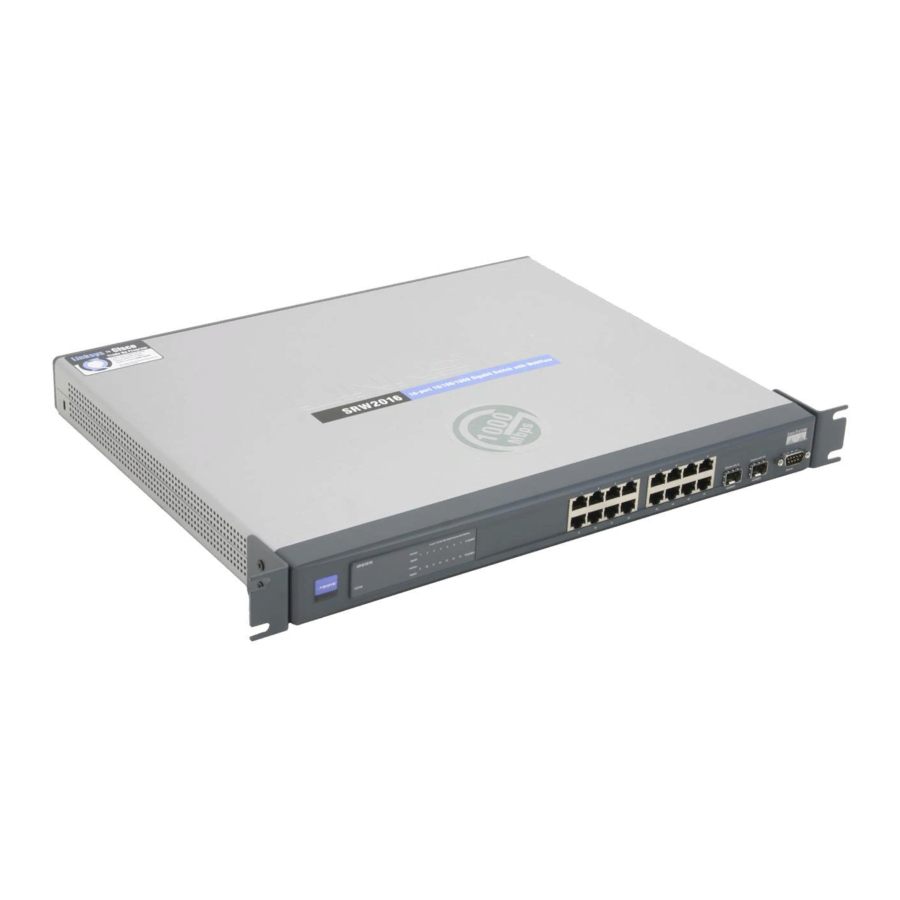
Chapter 2: Getting to Know the Switch Overview The 16- and 24-Port Switches differ in number of LEDs and ports. Pictured in this chapter is the 16-Port Switch; however, the other Switch is similar in form and function. The Front Panel The Switch's LEDs and ports are located on the front panel. -
Page 13: The Back Panel
Each mini-GBIC port provides a link to a high-speed network segment or individual workstation at speeds of up to 1000Mbps. Use the Linksys MGBT1, MGBSX1, or MGBLH1 mini-GBIC modules with the Switch. The MGBSX1 and the MGBLH1 require fiber cabling with LC connectors, while the MGBT1 requires a Category 5e Ethernet cable with an RJ-45 connector. -
Page 14: Chapter 3: Connecting The Switch
Chapter 3: Connecting the Switch Overview This chapter will explain how to connect network devices to the Switch. For an example of a typical network configuration, see the application diagram shown below. Figure 3-1: Typical Network Configuration for the 16-Port Switch When you connect your network devices, make sure you don’t exceed the maximum cabling distances, which are... -
Page 15: Before You Install The Switch
Placement Options Before connecting cables to the Switch, first you will physically install the Switch. Either set the Switch on its four rubber feet for desktop placement or mount the Switch in a standard-sized, 19-inch wide, 1U high rack for rack- mount placement. -
Page 16: Connecting The Switch
(This PC must be running the VT100 terminal emulation software, such as HyperTerminal.) 7. Connect the supplied power cord to the Switch’s power port, and plug the other end into an electrical outlet. IMPORTANT: Make sure you use the power cord that is supplied with the Switch. Use of a different power cord could damage the Switch. - Page 17 16- or 24-Port 10/100/1000 Gigabit Switch with WebView 8. Power on the network devices connected to the Switch. Each active port’s corresponding Link/Act LED will light up on the Switch. If a port has an active Gigabit connection, then its corresponding Gigabit LED will also light up.
-
Page 18: Chapter 4: Using The Console Interface For Configuration
2. On the Connection Description screen, enter a name for this connection. In the example, the name of connection is SRW2016. Select an icon for the application. Then click OK. 3. On the Connect To screen, select a port to communicate with the Switch, COM1, COM2, or TCP/IP. -
Page 19: Configuring The Switch Through The Console Interface
16- or 24-Port 10/100/1000 Gigabit Switch with WebView 4. Set the serial port settings as follows: Bits per second: 38400 Data bits: 8 Parity: None Stop bits: 1 Flow control: None Then click OK. Configuring the Switch through the Console Interface The console screens consist of a series of menus. -
Page 20: Figure 4-6: System Configuration Menu
6. Reboot System 0. Back to main menu System Information Using this screen, you can check the Switch’s firmware versions and general system information. Figure 4-7: System Information Versions The Versions screen displays the Switch’s boot, software, and hardware firmware versions. -
Page 21: Figure 4-9: General System Information
16- or 24-Port 10/100/1000 Gigabit Switch with WebView General System Information The General System Information screen displays the Switch’s description, System Up Time, System MAC Address, System Contact, System Name, and System Location. Select Edit to make changes. When your changes are complete, press the Esc key to return to the Action menu, and select Save to save your changes. -
Page 22: Figure 4-12: Telnet Configuration
Management VLAN. The VLAN ID number is displayed. DHCP client. The status of the DHCP client is displayed. If you want the Switch to be a DHCP client, then select ENABLE. If you want to assign an static IP address to the Switch, then enter the IP settings and select DISABLE. -
Page 23: Figure 4-15: Http
16- or 24-Port 10/100/1000 Gigabit Switch with WebView HTTP The HTTP screen displays the status and port number of the HTTP Server. Select Edit to make changes. When your changes are complete, press the Esc key to return to the Action menu, and select Save to save your changes. -
Page 24: Figure 4-17: Ping
16- or 24-Port 10/100/1000 Gigabit Switch with WebView Ping The Ping screen displays the IP address of the location you want to contact. Select Edit to change the IP address, and select Execute to begin the ping test. After the ping test is complete, the Ping screen displays the IP address, status, and statistics of the ping test. -
Page 25: Figure 4-20: Traceroute Test Results
Reboot System Select Reboot System and press the Enter key if you want to restart the Switch. You will be asked if you want to continue. Press the y key to reboot the Switch, or press the n key to cancel. After the Switch has rebooted, the Switch Main Menu screen will appear. -
Page 26: Figure 4-23: Port Status
16- or 24-Port 10/100/1000 Gigabit Switch with WebView Port Status On the Switch Main Menu screen, select Port Status and press the Enter key if you want to view the status information for the Switch’s ports. The Port Status screen displays the port numbers, their status, Link status, speed and duplex mode, and status of flow control, which is the flow of packet transmissions. -
Page 27: Chapter 5: Using The Web-Based Utility For Configuration
At the top of each screen is a picture of the 16- or 24-Port Switch. The LEDs display status information about their corresponding ports. A green LED indicates a connection, while a blue LED indicates no connection. When you click a port’s LED, the statistics for that port are displayed. -
Page 28: Sys. Info. (System Information) Tab - System Mode
Jumbo Frames. If you want to enable this feature on the Switch, select Enabled. You will be notified that this feature will be enabled after the Switch is reset. Otherwise, select Disabled. -
Page 29: Sys. Info. (System Information) Tab - Time Synchronization
Daylight Saving. Select Daylight Saving to enable it on the Switch. If the Switch should use US daylight savings, then select USA. If the Switch should use EU daylight savings, then select European. If it should use another kind of daylight savings, then select Other and complete the From and To fields. -
Page 30: Ip Conf. (Configuration) Tab - Ip Addr. (Address)
Click the Submit button to save your changes. Switch Conf. (Configuration) Tab - Interface Conf. (Configuration) The Interface Configuration screen shows you the port settings for the Switch. Interface#. This is the port number. Name. This is the device port ID. -
Page 31: Figure 5-9: Interface Configuration - Change Settings
The MDI setting is used if the port is connected to an end station. The MDIX setting is used if the port is connected to a hub or another switch. LAG. This indicates if the port is part of a LAG. - Page 32 MDI/MDIX. Select the Auto setting if you want the port to automatically detect the cable type. Select MDI if the port is connected to an end station. Select MDIX if the port is connected to a hub or another switch.
-
Page 33: Switch Conf. (Configuration) Tab - Vlan
16- or 24-Port 10/100/1000 Gigabit Switch with WebView Switch Conf. (Configuration) Tab - VLAN The VLAN screen lets you create subgroups of a LAN (Local Area Network) using software. The VLAN groups are listed on this screen. VLAN ID. This displays the VLAN ID number. -
Page 34: Switch Conf. (Configuration) Tab - La Conf. (Configuration)
Switch Conf. (Configuration) Tab - LA Conf. (Configuration) The Switch supports up to eight Link Aggregated Groups (LAGs), which maximize port usage by linking a group of ports together to form a single group. LAGs multiply the bandwidth between the network devices, increase port flexibility, and provide link redundancy. -
Page 35: Switch Conf. (Configuration) Tab - Port Mirroring
Switch Conf. (Configuration) Tab - Port Mirroring The Port Mirroring screen lets you configure the Switch’s port mirroring settings. Port mirroring can be used for diagnostics or debugging. It forwards copies of incoming and outgoing packets from one port to a monitoring port. -
Page 36: Qos Tab - Cos Settings
Weighted Round Robin (WRR), for which no single application dominates the forwarding capacity. The CoS Settings screen lets you enable or disable CoS for various ports. CoS Mode. This indicates whether CoS is enabled or disabled for the Switch. Interface. This indicates the interface to be configured. -
Page 37: Qos Tab - Cos To Queue
Click the Submit button to save your changes. Security Tab - ACL The ACL screen lists the access profiles and allows you to configure access profiles for the Switch. Access Profile. This is the name of the access profile. Activated. You can activate an access profile by selecting the radio button. You can deactivate an access profile Figure 5-22: Security Tab - ACL by deselecting the radio button. -
Page 38: Security Tab - 802.1X Users
Traffic is discarded if the state is forceUnauthorized. If the state is Auto, then that means the controlled port state is set by the authentication method. Quiet Period. This is the number of seconds the Switch remains in the quiet state after an authentication exchange has failed. -
Page 39: Figure 5-26: 802.1X Port Configuration - Change Settings
Supplicant Timeout. This is the number of seconds that the Switch waits before EAP requests are resent to the client. Server Timeout. This is the number of seconds that the Switch waits before it resends a request to the RADIUS server. -
Page 40: Security Tab - Management Conf. (Configuration)
Number of Retries. This is the number of requests sent to the RADIUS server before a failure occurs. Timeout for Reply. This is the number of seconds the Switch waits for an answer from the RADIUS server before retrying the query or switching to the next server. -
Page 41: Figure 5-29: Radius Server - Change Settings
Number of Retries. Enter the number of retries allowed before a failure occurs. To use the default, click the Use Default checkbox. Timeout for Reply. Enter the number of seconds the Switch waits for an answer from the RADIUS server before retrying the query or switching to the next server. To use the default, click the Use Default checkbox. -
Page 42: Security Tab - Tacacs Server
16- or 24-Port 10/100/1000 Gigabit Switch with WebView Default Timeout for Reply. Enter the default number of seconds the Switch waits for an answer from the RADIUS server before retrying the query or switching to the next server. Default Dead Time. Enter the default number of minutes that a RADIUS server is bypassed for service requests. -
Page 43: Security Tab - Storm Control
Key String. Enter the default key used for authentication and encryption. Timeout for Reply. Enter the default number of seconds the Switch waits for an answer from the RADIUS server before retrying the query or switching to the next server. -
Page 44: Security Tab - Authenticated Users
The Global Settings screen lets you set the Simple Network Time Protocol (SNTP) settings. SNTP makes possible accurate time synchronization by a network SNTP server for network devices. Using SNTP, the Switch is synchronized with the rest of the network and set with the correct time. -
Page 45: Sntp Tab - Authentication
Click the Submit button to save your change. Figure 5-36: SNTP - Authentication Encryption Key ID. Displayed here is the encryption key used to authenticate the SNTP server and Switch. Authentication Key. This is the key used for authentication. Trusted Key. This indicates if there is an encryption key used (unicast/anycast) or elected (broadcast) to authenticate the SNTP server. -
Page 46: Sntp Tab - Servers
Last Response. This describes the last response of the unicast server. Offset. This is the difference between the Switch’s time zone and the server’s time zone. Delay. This shows how long it takes for data from the server to travel to the Switch. Anycast Server Anycast Server. -
Page 47: Sntp Tab - Interface Settings
SNTP Server. Enter the IP address of an SNTP server. You can have up to eight SNTP servers. Poll Interval. Enable this feature if you want the Switch to poll the SNTP server for system time information. Figure 5-39: Servers - Change Settings Encryption Key ID. -
Page 48: Statistics Tab - Interface Statistics
16- or 24-Port 10/100/1000 Gigabit Switch with WebView Statistics Tab - Interface Statistics The Interface Statistics screen displays statistics for received and transmitted packets. Interface. Select the appropriate interface, Port, LAG, or VLAN. Then select the appropriate number from the drop-down menu. -
Page 49: Statistics Tab - Etherlike Statistics
16- or 24-Port 10/100/1000 Gigabit Switch with WebView Statistics Tab - Etherlike Statistics The Etherlike Statistics screen displays interface statistics. Interface. Select the appropriate interface, Port, LAG, or VLAN. Then select the appropriate number from the drop-down menu. Refresh Rate. Select how often you want the interface statistics refreshed. -
Page 50: Statistics Tab - Rmon Statistics
Refresh Rate. Select how often you want the interface statistics refreshed. Drop Events. This is the number of dropped events that have occurred on the interface since the Switch was last refreshed. Received Bytes. This is the number of octets received on the interface since the Switch was last refreshed. (This number excludes framing bits.) -
Page 51: Statistics Tab - Rmon History Control
16- or 24-Port 10/100/1000 Gigabit Switch with WebView Frames of 64 Bytes. This is the number of 64-byte frames received on the interface since the Switch was last refreshed. Frames of 65 to 127 Bytes. This is the number of 65- to 127-byte frames received on the interface since the Switch was last refreshed. -
Page 52: Statistics Tab - Rmon History Log
Multicast Packets. This is the number of good multicast packets received on the interface since the Switch was last refreshed. CRC Align Errors. This is the number of CRC and Align errors that occurred on the interface since the Switch was last refreshed. -
Page 53: Statistics Tab - Rmon Alarms
Jabbers. This is the total number of received packets that were longer than 1518 octets. (This number excludes frame bits.) Collisions. This is the number of collisions received on the interface since the Switch was last refreshed. Utilization. This is the percentage of packet utilization across the entire Switch. -
Page 54: Statistics Tab - Rmon Events Control
16- or 24-Port 10/100/1000 Gigabit Switch with WebView Interval. This is the alarm interval, measured in seconds. Owner. This is the user who requested this alarm. To delete an entry, click its X icon. To add an entry, click the paper and pencil icon. On the new screen that appears, you can configure its settings. -
Page 55: Statistics Tab - Rmon Events Log
16- or 24-Port 10/100/1000 Gigabit Switch with WebView Description. This is the description of the event. Type. This is the event type, Log, Trap, Log and Trap, or None. Log indicates that the event is a log entry. Trap indicates that the event is a trap. An event can be both a log entry and a trap. None indicates that no event has occurred. -
Page 56: Statistics Tab - Eap Statistics
16- or 24-Port 10/100/1000 Gigabit Switch with WebView Statistics Tab - EAP Statistics The EAP Statistics screen displays information about EAP packets received on a specific port. Port. Select the port you want to poll for statistics. Refresh Rate. Select how often you want the EAP statistics to be refreshed. -
Page 57: Logs Tab - Event Log
The Global Parameters screen lets you define which events are recorded by which logs. You can enable logs for the Switch and define specific logs. Logging. If you want the Switch to keep logs, select Enable. Otherwise, select Disable. Attribute. Displayed here is Max RAM Log Entries (20-400). This stands for the maximum number of log entries held in RAM. -
Page 58: Maintenance Tab - Telnet
Reset the Device. If you want to reset the Switch, click Reset the Device. You will be asked to confirm the reset. Click the OK button. After the Switch is reset, you will be prompted for a user name and password before you can access the Web-based Utility. -
Page 59: Maintenance Tab - File Upload
Configuration file holds all startup file commands and commands entered during the current session. The Startup Configuration file holds the startup file commands needed by the Switch to power on or be rebooted. Click the Submit button to begin the download of the firmware or configuration file. -
Page 60: Maintenance Tab - Restore Defaults
Configuration file holds all startup file commands and commands entered during the current session. The Startup Configuration file holds the startup file commands needed by the Switch to power on or be rebooted. Click the Submit button to begin the upload of the firmware or configuration file. -
Page 61: Maintenance Tab - Http File Download
Maintenance Tab - HTTP File Download The HTTP File Download screen allows you to download a file to the Switch via HTTP. Source File Name. Enter the file path of the file you want to download, or click the Browse button to browse for the source file. -
Page 62: Appendix A: About Gigabit Ethernet And Fiber Optic Cabling
A fiber connection always require two fiber cables: one transmits data, and the other receives it. Each fiber optic cable is tipped with a connector that fits into a fiber port on a network adapter, hub, or switch. In the USA, most cables use a square SC connector that slides and locks into place when plugged into a port or connected to another cable. -
Page 63: Appendix B: Windows Help
16- or 24-Port 10/100/1000 Gigabit Switch with WebView Appendix B: Windows Help Almost all networking products require Microsoft Windows. Windows is the most used operating system in the world and comes with many features that help make networking easier. These features can be accessed through Windows Help and are described in this appendix. -
Page 64: Appendix C: Glossary
16- or 24-Port 10/100/1000 Gigabit Switch with WebView Appendix C: Glossary Adapter - A device that adds network functionality to your PC. AES (Advanced Encryption Standard) - A security method that uses symmetric 128-bit block data encryption. Backbone - The part of a network that connects most of the systems and networks together, and handles the most data. - Page 65 16- or 24-Port 10/100/1000 Gigabit Switch with WebView DDNS (Dynamic Domain Name System) - Allows the hosting of a website, FTP server, or e-mail server with a fixed domain name (e.g., www.xyz.com) and a dynamic IP address. Default Gateway - A device that forwards Internet traffic from your local area network.
- Page 66 16- or 24-Port 10/100/1000 Gigabit Switch with WebView Firewall - A set of related programs located at a network gateway server that protects the resources of a network from users from other networks. Firmware - The programming code that runs a networking device.
- Page 67 Packet - A unit of data sent over a network. Passphrase - Used much like a password, a passphrase simplifies the WEP encryption process by automatically generating the WEP encryption keys for Linksys products. PEAP (Protected Extensible Authentication Protocol) - A mutual authentication method that uses a combination of digital certificates and another system, such as passwords.
- Page 68 Subnet Mask - An address code that determines the size of the network. Switch - 1. A data switch that connects computing devices to host computers, allowing a large number of devices to share a limited number of ports. 2. A device for making, breaking, or changing the connections in an electrical circuit.
- Page 69 16- or 24-Port 10/100/1000 Gigabit Switch with WebView Throughput - The amount of data moved successfully from one node to another in a given time period. Topology - The physical layout of a network. TX Rate - Transmission Rate. UDP (User Datagram Protocol) - A network protocol for transmitting data that does not require acknowledgement from the recipient of the data that is sent.
-
Page 70: Appendix D: Specifications
SRW2024 - 24-Port 10/100/1000 Gigabit Switch with WebView Standards IEEE 802.3, 802.3u, 802.3ab, 802.3x, 802.1p, 802.1q Ports SRW2016 - 16 10/100/1000 RJ-45 ports and 2 shared MiniGBIC slots SRW2024 - 24 10/100/1000 RJ-45 ports and 2 shared MiniGBIC slots Cabling Type Cat5e or better... -
Page 71: Appendix E: Warranty Information
Your exclusive remedy and Linksys' entire liability under this warranty will be for Linksys at its option to repair or replace the Product or refund Your purchase price less any rebates. -
Page 72: Appendix F: Regulatory Information
16- or 24-Port 10/100/1000 Gigabit Switch with WebView Appendix F: Regulatory Information FCC STATEMENT This product has been tested and complies with the specifications for a Class B digital device, pursuant to Part 15 of the FCC Rules. These limits are designed to provide reasonable protection against harmful interference in a residential installation. -
Page 73: Appendix G: Contact Information
Can't find information about a product you want to buy on the web? Do you want to know more about networking with Linksys products? Give our advice line a call at: Or fax your request in to: If you experience problems with any Linksys product,...