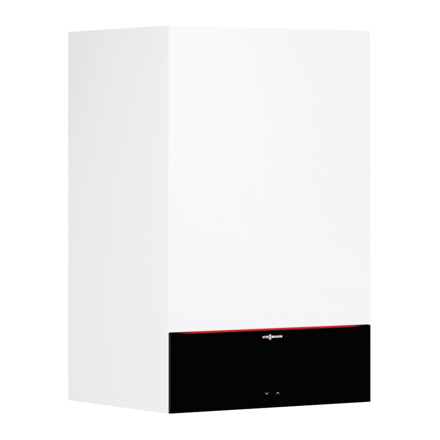
Viessmann Vitodens 100-W Installation Instructions Manual
Replacing the control unit
Hide thumbs
Also See for Vitodens 100-W:
- Installation instructions manual (204 pages) ,
- Installation and service instructions manual (105 pages) ,
- Manual (84 pages)
Table of Contents
Advertisement
Quick Links
Installation instructions
for contractors
Replacing the control unit
for the Vitodens 100-W
Safety instructions
Please follow these safety instructions closely to prevent accidents and
material losses.
Safety instructions explained
!
Please note
This symbol warns against the
risk of material losses and envi-
ronmental pollution.
Note
Details identified by the word "Note" con-
tain additional information.
Installation, initial start-up, inspection,
maintenance and repairs must only be
carried out by a competent person (heat-
ing engineer/installation contractor).
Before working on the equipment/heat-
ing system, isolate the power supply
(e.g. by removing a separate mains fuse
or by means of a mains isolator) and
safeguard against unauthorised recon-
nection.
Opening the Vitodens
Installation and service instruc-
tions
5602 997 GB
4/2012
VIESMANN
When using gas as fuel, also close the
main gas shut-off valve and safeguard
against unauthorised reopening.
Repairing components which fulfil a
safety function can compromise the safe
operation of your heating system.
For replacements, use only original
spare parts supplied or approved by
Viessmann.
Dispose after installation.
Advertisement
Table of Contents

Summary of Contents for Viessmann Vitodens 100-W
-
Page 1: Installation Instructions
VIESMANN Installation instructions for contractors Replacing the control unit for the Vitodens 100-W Safety instructions Please follow these safety instructions closely to prevent accidents and material losses. Safety instructions explained When using gas as fuel, also close the Please note... -
Page 2: Replacing The Control Unit
Replacing the control unit Please note Before beginning work, touch Electronic assemblies can be earthed objects, such as heating damaged by electrostatic dis- or water pipes, to discharge static charge. loads. 1. Push in the side locking tabs. 5. Push in the side locking tabs and remove the pressure gauge from the 2. -
Page 3: Matching The Control Unit To The Boiler
Replacing the control unit (cont.) 7. Remove the control unit from the floor 9. Fit the pressure gauge into the con- of the air box. trol unit casing. 8. Secure the new control unit with two 10. Connect all plugs to the control screws on the floor of the air box. - Page 4 Matching the control unit to the boiler (cont.) 4. Turn rotary selector "rt" fully anti- clockwise within 2 s. In the display the value for the selec- ted parameter set (1 - 12) flashes. 5. Select the parameter set that suits the boiler in accordance with the fol- lowing table and the serial number (see type plate).
-
Page 5: Changing The Gas Type At The Control Unit
Matching the control unit to the boiler (cont.) 10. If a lead was previously connected to "X 21" at the control unit (remote control unit or outside temperature sensor): Reconnect this lead to "X 21". Serial no. Parameter set Serial no. Parameter set (Type plate) (Type plate) -
Page 6: Matching The Burner Output To The Flue System
Changing the gas type at the control unit (cont.) 1. Switch on the ON/OFF switch. 2. Turn both rotary selectors "tw" and "tr" simultaneously into their respective central positions. "SERV" appears on the display. 3. Turn rotary selector "tr" fully anti- clockwise within 2 s . -
Page 7: Closing The Control Unit And Starting The Boiler
Closing the control unit and starting the boiler 1. Close the control unit casing and flip 3. Start up the boiler and check for cor- up the control unit. rect function. 2. Fit the front panel. - Page 8 Viessmann Werke GmbH&Co KG Viessmann Limited D-35107 Allendorf Hortonwood 30, Telford Telephone: +49 6452 70-0 Shropshire, TF1 7YP, GB Fax: +49 6452 70-2780 Telephone: +44 1952 675000 www.viessmann.com Fax: +44 1952 675040 E-mail: info-uk@viessmann.com...


