Table of Contents
Advertisement
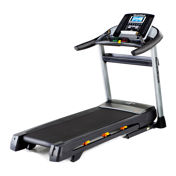
Model No. NETL14714.0
Serial No.
USER'S MANUAL
Write the serial number in the space
above for reference.
Serial Number
Decal
CUSTOMER SERVICE
UNITED KINGDOM
Call: 08457 089 009
From Ireland: 053 92 36102
Website: www.iconsupport.eu
E-mail: csuk@iconeurope.com
Write:
ICON Health & Fitness, Ltd.
c/o HI Group PLC
Express Way
CASTLEFORD
WF10 5QJ
UNITED KINGDOM
AUSTRALIA
Call: 1800 993 770
E-mail: australiacc@iconfitness.com
Write:
ICON Health & Fitness
PO Box 635
WINSTON HILLS NSW 2153
AUSTRALIA
CAUTION
Read all precautions and instruc-
tions in this manual before using
this equipment. Save this manual
for future reference.
www.iconeurope.com
Advertisement
Table of Contents

Related Manuals for NordicTrack T17.5


Summary of Contents for NordicTrack T17.5
- Page 1 Model No. NETL14714.0 Serial No. USER’S MANUAL Write the serial number in the space above for reference. Serial Number Decal CUSTOMER SERVICE UNITED KINGDOM Call: 08457 089 009 From Ireland: 053 92 36102 Website: www.iconsupport.eu E-mail: csuk@iconeurope.com Write: ICON Health & Fitness, Ltd. c/o HI Group PLC Express Way CASTLEFORD...
-
Page 2: Table Of Contents
Apply the decal in the location shown. Note: The decals may not be shown at actual size. 305284 NORDICTRACK is a registered trademark of ICON IP, Inc. -
Page 3: Important Precautions
IMPORTANT PRECAUTIONS WARNING: To reduce the risk of burns, fire, electric shock, or injury to persons, read all important precautions and instructions in this manual and all warnings on your treadmill before using your treadmill. ICON assumes no responsibility for personal injury or property damage sus- tained by or through the use of this product. -
Page 4: Assembly
DANGER: 21. Do not attempt to move the treadmill until Always unplug the power it is properly assembled. (See ASSEMBLY cord immediately after use, before clean- on page 7 and HOW TO FOLD AND MOVE ing the treadmill, and before performing the THE TREADMILL on page 28.) You must be maintenance and adjustment procedures able to safely lift 45 lbs. -
Page 5: Before You Begin
BEFORE YOU BEGIN Thank you for selecting the revolutionary reading this manual, please see the front cover of this NORDICTRACK T 17.5 treadmill. The T 17.5 treadmill manual. To help us assist you, please note the product ® offers an impressive selection of features designed model number and serial number before contacting us. -
Page 6: Part Identification Chart
PART IDENTIFICATION CHART Use the drawings below to identify small parts used for assembly. The number in parentheses below each draw- ing is the key number of the part, from the PART LIST near the end of this manual. The number following the key number is the quantity used for assembly. -
Page 7: Assembly
ASSEMBLY • Assembly requires two persons. • To identify small parts, see page 6. • Place all parts in a cleared area and remove the • Assembly requires the following tools: packing materials. Do not dispose of the packing materials until you finish all assembly steps. the included hex key •... - Page 8 2. Make sure that the power cord is unplugged. Wire Press the two Base Caps (74) into the Base (94), if they are not already in the Base. Identify the Right Upright (90). Remove and discard the indicated screw (A). Have a sec- ond person hold the Right Upright near the Base (94).
- Page 9 4. Insert a Wheel Spacer (63) into a Front Wheel (62). Hold the Front Wheel inside the bottom of the Right Upright (90), and insert a 3/8" x 4" Screw (7) with a 3/8" Star Washer (13) into the Right Upright and the Front Wheel. Repeat this step with the Left Upright (not shown).
- Page 10 6. Remove and save the four indicated 5/16" x 3/4" Screws (4); the Screws will be used in a later step. Identify the Left and Right Base Covers (82, 83). Slide the Left Base Cover onto the Left Upright (89), and slide the Right Base Cover onto the Right Upright (90).
- Page 11 8. Attach a Handrail (86) to the Right Upright (90) with two 5/16" x 2 1/2" Screws (28) and two 5/16" Star Washers (11). Be careful not to pinch the Upright Wire (81). Do not fully tighten the Screws yet. Attach the other Handrail (86) to the Left Upright (89) in the same way.
-
Page 12: Assembly
10. Set the console assembly face down on a soft surface to avoid scratching the console assembly. Attach the Right and Left Trays (27, 36) with eight #8 x 1/2" Screws (1). Do not overtighten the Screws. Remove the four indicated 1/4" x 1/2" Screws (31) from the Console Frame (18);... - Page 13 13. Set the console assembly on the brackets on the Handrails (86). Be careful not to pinch any Console wires. Assembly Attach the console assembly with the four 1/4" x 1/2" Screws (31) that you removed in step 10 and four 1/4" Star Washers (32). Start all four Screws, and then tighten them.
-
Page 14: Assembly
15. Connect the ground wires (E), the 8-pin wires (F), the 10-pin wires (G), and the four speaker wires (H). Note: The Upright Wire (81) has 8 pins, the pulse wire (D) has 10 pins, and the speaker wires (H) have 2 pins. See the inset drawing. - Page 15 17. Carefully slide the Upright Crossbar (41) between the Uprights (89, 90). Attach the Upright Crossbar with the four 5/16" x 3/4" Screws (4) that you removed in step 6 and four 5/16" Star Washers (11). Start all four Screws, and then tighten them.
- Page 16 19. Attach the Console Cover (105) with two #8 x 3/4" Screws (2). Tighten the six 3/8" x 4" Screws (7). Then, press the Base Covers (82, 83) into place. 20. Note: If assembled on a smooth surface, the treadmill may roll forward during this step. Brackets Raise the Frame (56) to the upright position.
- Page 17 21. Orient the Storage Latch (53) so that the decal is facing away from the treadmill as shown. Attach the lower end of the Storage Latch (53) to the bracket on the Base (94) with a 5/16" x 1 3/4" Bolt (6) and a 5/16"...
-
Page 18: The Chest Heart Rate Monitor
THE CHEST HEART RATE MONITOR HOW TO PUT ON THE HEART RATE MONITOR • Do not expose the heart rate monitor to direct sun- light for extended periods of time; do not expose it to The heart rate temperatures above 122° F (50° C) or below 14° F monitor consists of (-10°... -
Page 19: How To Use The Treadmill
HOW TO USE THE TREADMILL HOW TO PLUG IN THE POWER CORD Follow the steps below to plug in the power cord. This product must be earthed. If it should malfunc- 1. Plug the indicated end of the power cord into the tion or break down, earthing provides a path of least socket on the treadmill. - Page 20 CONSOLE DIAGRAM FEATURES OF THE CONSOLE You can even listen to your favorite workout music or audio books with the console’s sound system while you The treadmill console offers an impressive array of exercise. features designed to make your workouts more effec- To turn on the power, see page 21.
- Page 21 HOW TO TURN ON THE POWER HOW TO USE THE MANUAL MODE IMPORTANT: If the treadmill has been exposed to 1. Insert the key into the console. cold temperatures, allow it to warm to room tem- perature before you turn on the power. If you do See HOW TO TURN ON THE POWER at the left.
- Page 22 5. Follow your progress with the displays. Press the Home button to return to the default menu (see THE SETTINGS MODE on page 26 As you walk or run on the treadmill, the display can to set the default menu). If necessary, press the show the following workout information: Home button again.
- Page 23 7. Turn on the fan if desired. 3. Start the workout. The fan features several Press the Start button or the Speed increase button speed settings and an auto to start the workout. A moment after you press the mode. When the auto mode button, the treadmill will automatically adjust to the is selected, the speed of first speed and incline settings of the workout.
- Page 24 If the speed or incline setting is too high or too low a calorie, time, or distance workout, press the at any time during the workout, you can manu- increase and decrease buttons next to the Enter ally override the setting by pressing the Speed or button and then press the Enter button.
- Page 25 HOW TO USE AN IFIT WORKOUT When you select an iFit workout, the display will show the duration of the workout, the distance you Note: To use an iFit workout, you must have an will walk or run, and the approximate number of optional iFit module.
- Page 26 7. Measure your heart rate if desired. THE SETTINGS MODE See step 6 on page 22. The console features an information mode that keeps track of treadmill information and allows you to person- 8. Turn on the fan if desired. alize console settings.
- Page 27 CONTRAST LVL—Press the Incline increase and HOW TO ADJUST THE CUSHIONING SYSTEM decrease buttons to adjust the contrast level of the display. The treadmill features a cushioning system that reduces the impact as you walk or run on the treadmill. If a module is connected, you may also select the following screen: Remove the key from the console and unplug the...
-
Page 28: How To Fold And Move The Treadmill
HOW TO FOLD AND MOVE THE TREADMILL HOW TO FOLD THE TREADMILL HOW TO MOVE THE TREADMILL To avoid damaging the treadmill, adjust the incline Before moving the treadmill, fold it as described at the to zero before you fold the treadmill. Then, remove left. -
Page 29: Maintenance And Troubleshooting
MAINTENANCE AND TROUBLESHOOTING MAINTENANCE b. Make sure that the power cord is plugged in. If the power cord is plugged in, unplug it, wait for five Regularly clean the treadmill and keep the walking minutes, and then plug it back in. belt clean and dry. - Page 30 Locate the Reed Switch (52) and the Magnet (50) b. If the walking belt is overtightened, treadmill per- on the left side of the Pulley (49). Turn the Pulley formance may decrease and the walking belt may until the Magnet is aligned with the Reed Switch. become damaged.
- Page 31 SYMPTOM: The walking belt is not centered SYMPTOM: The walking belt slips when walked on between the foot rails a. First, remove the key and UNPLUG THE POWER IMPORTANT: If the walking belt rubs against the CORD. Using the hex key, turn both idler roller foot rails, the walking belt may become damaged.
-
Page 32: Exercise Guidelines
EXERCISE GUIDELINES Burning Fat—To burn fat effectively, you must exer- WARNING: cise at a low intensity level for a sustained period of Before beginning this time. During the first few minutes of exercise, your or any exercise program, consult your physi- body uses carbohydrate calories for energy. -
Page 33: Suggested Stretches
SUGGESTED STRETCHES The correct form for several basic stretches is shown at the right. Move slowly as you stretch —never bounce. 1. Toe Touch Stretch Stand with your knees bent slightly and slowly bend forward from your hips. Allow your back and shoulders to relax as you reach down toward your toes as far as possible. -
Page 34: Part List
PART LIST Model No. NETL14714.0 R0214A Key No. Qty. Description Key No. Qty. Description #8 x 1/2" Screw Reed Switch Clip #8 x 3/4" Screw Reed Switch 5/16" x 2 1/4" Bolt Storage Latch 5/16" x 3/4" Screw Drive Motor #10 Star Washer Motor Belt 5/16"... - Page 35 Key No. Qty. Description Key No. Qty. Description Hood Post Right Frame Cover Console Clamp Electronics Bracket Right Speaker Cover Base Pad Console Base Back Motor Isolator Console Cover Motor Bushing #8 x 5/8" Screw #8 Nut Speaker #8 x 3/4" Machine Screw Heart Rate Monitor Electronics Bracket Incline Motor Spacer...
-
Page 36: Exploded Drawing
EXPLODED DRAWING A Model No. NETL14714.0 R0214A... - Page 37 EXPLODED DRAWING B Model No. NETL14714.0 R0214A...
- Page 38 EXPLODED DRAWING C Model No. NETL14714.0 R0214A...
- Page 39 EXPLODED DRAWING D Model No. NETL14714.0 R0214A...
-
Page 40: Ordering Replacement Parts
ORDERING REPLACEMENT PARTS To order replacement parts, please see the front cover of this manual. To help us assist you, be prepared to provide the following information when contacting us: • the model number and serial number of the product (see the front cover of this manual) •...