Linear DVS-1200 Installation & Programming Instructions
Supervised wireless security console
Hide thumbs
Also See for DVS-1200:
- Software manual (48 pages) ,
- Installation instructions manual (44 pages) ,
- Installation instructions manual (44 pages)

Related Manuals for Linear DVS-1200


Summary of Contents for Linear DVS-1200
- Page 1 SUPERVISED WIRELESS SECURITY CONSOLE Installation & Programming Instructions USA & Canada (800) 421-1587 & (800) 392-0123 (760) 438-7000 - Toll Free FAX (800) 468-1340 www.linearcorp.com...
- Page 2 Inform the user to ask their insurance agent about savings available. The DVS-1200 Console is UL Listed. For a UL smoke alarm system, there must be at least one smoke detector programmed into the Console to meet National Fire Protection Association (NFPA) Rule 72 Chapter 2 and UL 217 requirements.
-
Page 3: Table Of Contents
1. THE DVS-1200 SECURITY SYSTEM ........ -
Page 4: The Dvs-1200 Security System
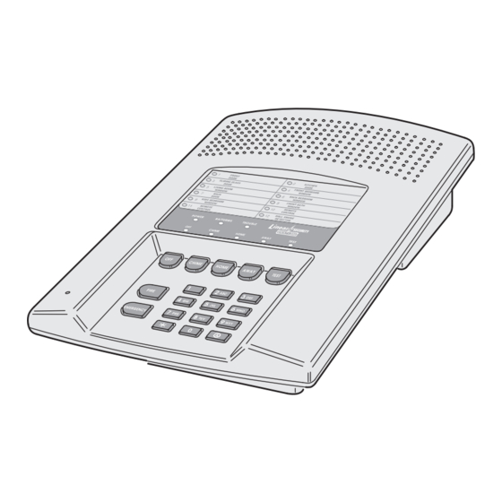
SENSOR SENSOR CONSOLE The DVS-1200 Console is the heart of the system. It monitors all of the system’s wireless sensors and controls the alarm sirens. The Console constantly monitors the condition of the system’s sensors, displaying which protected doors and windows are open or closed. -
Page 5: Door/Window Sensors
DOOR/WINDOW SENSORS The DXS-31 and DXS-32 sensors monitor doors and windows. They send radio signals to the Console. One type of signal is sent when the door or window is opened, and a different type of signal is sent when the door or window is closed. If the Console is armed, a sensor can trigger the Console's burglary siren when its door or window is opened. -
Page 6: Security System Floor Plan
SECURITY SYSTEM FLOOR PLAN EXAMPLE SYSTEM ✦ The example shows a typical DVS-1200 system. ✦ Any or all of the accessories shown can be used. ✦ A total of 12 sensors can be used with each Console DESIGN THE INSTALLATION 1. -
Page 7: Door/Window Sensor
TYPICAL SYSTEM SENSORS DOOR/WINDOW SENSOR ✦ Sensor mounts on door or window with adjacent magnet. ✦ Opening door or window moves magnet away, triggering sensor. ✦ Pressing the case causes sensor to send a test signal. ✦ Jumper inside for INSTANT or DELAYED alarm setting. -
Page 8: Console Features
CONSOLE FEATURES 24-HOUR BUTTONS ★ Pressing FIRE for two seconds sounds the fi re siren and sends a “fi re” message to a central monitoring station through the digital communicator (if the system is monitored). ★ Pressing EMERGENCY for two seconds sounds the emergency siren and sends an “emergency”... - Page 9 10 AUXILIARY FUSE ★ Type 2AG, 1-amp fuse. ★ Protects the external relay output when used with wet contacts (12 VDC switched out). ★ Fuse will blow when load exceeds 1 amp. ✎ WARNING: For continued protection against the risk of fi re, replace only with the same type and rating of fuse.
-
Page 10: Console Installation
CONSOLE INSTALLATION CONSOLE LOCATION ✎ NOTE: Wireless sensor signals must be able to reach the Console. ✔ Try to centrally locate the Console. ✔ Keep Console away from large metal appliances. ✔ Maximum recommended sensor range is 400 feet (system tested at 1000 feet). ✎... -
Page 11: External Console Speaker Connection
✎ NOTE: By removing the Console’s auxiliary fuse, the relay contacts will become isolated. Use the RELAY N.O. & RELAY DRY terminals to switch an externally powered load. LINEAR SECURITY CONSOLE MODEL DVS-1200 ANNUNCIATOR 8 OHM/10 WATT VOLUME 2 SPKRS MAX. -
Page 12: Telephone Line Connection
Console’s telephone terminal block SEIZED TIP and SEIZED RING terminals. ✦ When directly connecting (without a telephone line) to the DVS-1200 with the RA-2400 remote access software (Version 1.3 or later), disconnect the incoming telephone line and connect the modem to the panel's TIP and RING terminals (with the modem's red &... -
Page 13: Console Power Connection
3. Connect the black battery lead to the negative battery terminal. 4. Connect the red battery lead to the positive battery terminal. ✎ WARNING: DO NOT REVERSE THE BATTERY LEADS! THE BATTERY FUSE WILL BLOW. LINEAR SECURITY CONSOLE MODEL DVS-1200 PLUG-IN TRANSFORMER MAIN TERMINAL BLOCK OPTIONAL... -
Page 14: Basic Console Programming
BASIC CONSOLE PROGRAMMING ✦ In a new installation, when power is fi rst applied the system's master user code is “1234”. CREATE THE MASTER USER CODE ✎ NOTE: Local programming must be entered on the Console's keypad, not on a wireless remote keypad. -
Page 15: Programming Different Sensor Types
PROGRAMMING DIFFERENT SENSOR TYPES ✦ Follow the instructions on the previous page to select a sensor number to program the sensor into. ✎ NOTE: A sensor can be programmed into more than one location. Be sure to choose an UNUSED sensor number. -
Page 16: Basic Sensor Installation
✦ Refer to the sensor's instructions for details on installing, operating, and testing of the sensor. ✦ Following are basic instructions for installing two popular DVS-1200 accessories: The Model DXS-10 Wireless Remote Keypad and the Model DXS-31 or DXS-32 Door/Window Transmitters. -
Page 17: Dxs-31 & Dxs-32 Door/Window Sensors
DXS-31 & DXS-32 DOOR/WINDOW SENSORS ✦ The DXS-31 and DXS-32 sensors can be used to monitor doors, windows, cabinets, crawl space doors, gates, freezer doors, and many other moving objects that could be used for intrusion or need to be monitored. ✦... -
Page 18: Customizing The Console
CUSTOMIZING THE CONSOLE ✦ The Console can be customized for the specifi c installation. ✦ A label sheet with sensor location names is provided with the Console. ✦ Labeling the sensors allows quick and easy identifi cation of where a door or window is open, where any alarms have occurred, where a sensor with a low battery is, or where a sensor with trouble LABELING THE SENSORS... -
Page 19: Off Mode
CONSOLE OPERATING MODES OFF MODE ✦ Use this mode to disarm the burglary portion of the system. ✦ Switching to Off Mode stops any alarms in progress. ✦ The 24-hour functions are still active in Off Mode and can be triggered by pressing the FIRE or EMERGENCY button. -
Page 20: Home Mode
HOME MODE ✦ Use this mode when sleeping or when anyone is staying inside. ✦ Home Mode causes an instant alarm when any perimeter sensor is triggered. ✦ Home Mode causes a delayed alarm when any exit/ entry sensor is triggered (except in Home Instant Mode when they are instant). -
Page 21: Away Mode
AWAY MODE ✦ Use this mode when no one will be staying home. ✦ Each burglary sensor can trigger the siren once per arming period. ✦ Away Mode causes an instant alarm when any perimeter sensor is triggered. ✦ Away Mode causes a delayed alarm when any exit/entry sensor is triggered. -
Page 22: Test Mode
Mode, it will automatically switch back to Off Mode after three minutes. ✦ When directly connecting (without a telephone line) to the DVS-1200 with the RA-2400 remote access software (Version 1.3 or later), press the EMERGENCY key while in Test Mode to cause the Console to connect to the modem. -
Page 23: Console Low Battery
10. SYSTEM TROUBLE INDICATIONS ✦ The DVS-1200 Console is a self-monitoring supervised wireless system. ✦ If the Console detects a problem with any of the supervised system sensors or with its power, it will display the appropriate trouble indication and,... -
Page 24: Customizing The System
11. CUSTOMIZING THE SYSTEM ✦ Adding additional sensors will increase the protection provided by the system. ✦ All ground-level perimeter openings and accessible upper-story openings need protection. ✦ Motion detectors can protect interior areas and areas where valuables are kept. ADDING SENSORS TO THE SYSTEM 1. -
Page 25: Making A Sensor A 24-Hour Door Chime
MAKING A SENSOR A 24-HOUR DOOR CHIME ✦ Sensors can be programmed to cause the Console to chime any time they're activated. ✦ Chime-only sensors will not be able to trigger the alarm in any Console mode. ✦ The sensor must have already been programmed into the Console (see “Adding Sensors to the System”... -
Page 26: Making A Sensor Perform A Different Function
MAKING A SENSOR PERFORM A DIFFERENT FUNCTION ✦ Sensors can be reprogrammed to perform different sensor functions. ✦ The sensor must have already been programmed into the Console (see “Adding sensors to the System” for details). 1. Start with the Console in Test Mode. 2. -
Page 27: 12. Advanced Programming
12. ADVANCED PROGRAMMING ✦ To perform any of the advanced programming steps, the Console must be in the Setup Mode. ✦ Each programming function is performed with similar keystrokes. After the Console is in Setup Mode, enter the programming step number, press HOME, then enter the new value and press AWAY. -
Page 28: Changing A Sensors Supervision
CHANGING A SENSORS SUPERVISION ✦ When a sensor is programmed, the Console automatically recognizes it as supervised or non-supervised. ✦ The Console expects hourly status transmissions from any sensor programmed as supervised. ✦ Any sensor can be programmed as supervised or non-supervised. -
Page 29: Fire Siren Time
FIRE SIREN TIME ✦ The factory-set fi re siren time is fi ve minutes (UL installation maximum). STEP #32 The fi re siren time can be adjusted from one to 30 minutes using this step. AUTOMATION OUTPUT TIME ✦ The factory setting causes the Automation Output to toggle between on and off with each activation. -
Page 30: Silent Burglary Alarms
SILENT BURGLARY ALARMS ✦ The factory setting causes audible burglary alarms. STEP #63 The Console can be programmed for silent burglary alarms using this step. SILENT EMERGENCY ALARMS ✦ The factory setting causes audible emergency alarms. STEP #64 The Console can be programmed for silent emergency alarms using this step. -
Page 31: Automation Output Mode During Alarm
AUTOMATION OUTPUT MODE DURING ALARM ✦ The factory setting causes the Automation Output to fl ash if it is programmed to activate during or after an alarm. ✎ NOTE: For the Automation Output to activate during or after an alarm, that function must be enabled with Programming Step 71 or 72. -
Page 32: Automation Output While Armed
AUTOMATION OUTPUT WHILE ARMED ✦ The factory setting causes the Console's Automation Output to activate when pressing the key, or when it's triggered with a two-button remote control. STEP #73 The Console can be programmed to activate the Automation Output when the system is armed as well as when normally triggered using this step. -
Page 33: Adding Additional User Codes
ADDING ADDITIONAL USER CODES ✦ The Console can be programmed with fi ve restricted user codes and one page alert user code. ✦ The restricted user codes operate the system as usual, but cannot access Setup Mode. ✦ The restricted user codes can access a special Code Mode that can be used to change or remove any of the fi... -
Page 34: Communicator Programming
13. COMMUNICATOR PROGRAMMING ✦ To perform any of the communicator programming steps, the Console must be in the Setup Mode. ✦ Each programming function is performed with similar keystrokes. After the Console is in Setup Mode, enter the programming step number and press HOME, then enter the new value and press AWAY. -
Page 35: Communicator Enable
REMOTE LOCKOUT ✦ The factory setting for the communicator allows remote connection to the Console with Linear's RA-2400 Remote Access Software and a modem (unlocked). STEP #100 The Console can be programmed to not answer incoming calls, thereby, not allowing remote access (locked) using this step. -
Page 36: Call Limiter
CALL LIMITER ✦ The factory setting for the call limiter is OFF. This allows the communicator to report burglary alarms, once for each sensor, as many times as they are triggered. STEP #101 The Console can be programmed to only allow fi ve burglary reports total per arming period using this step. -
Page 37: Reporting Format
REPORTING FORMAT ✦ The factory setting causes the communicator to report using the 4 BY 2 FORMAT. This format allows four-digit account numbers from 0000 to 9999 and provides two-digit alarm codes. STEP #105 ADEMCO CONTACT ID can be chosen as a reporting format using this step. -
Page 38: Account Number
ACCOUNT NUMBER ✦ The account number entered for the communicator must be 4-digits long. ✦ The factory setting for the account number is 0000. STEP #88 Enter an account number from 0000 to 9999 using this step. PRIMARY TELEPHONE NUMBER ✦... -
Page 39: Report Console Trouble
REPORT CONSOLE TROUBLE ✦ The factory setting does not report Console trouble events to the Central Station. STEP #108 The communicator can be programmed to report Console trouble events using this step. These include all conditions that light the Console’s BATTERIES or TROUBLE indicator. -
Page 40: General Reporting Codes
✦ The 4 by 2 two-digit communicator reporting code for each event has a factory set value. These values may be customized to fi t the specifi c installation and the reporting requirements of the Central Station monitoring the system. ✦... -
Page 41: System Reporting Codes
SYSTEM REPORTING CODES ✦ Refer to the System Reporting Codes table to view/edit the reporting codes for the keypad FIRE and EMERGENCY buttons and for each of the four Console conditions. The factory settings are listed, along with a blank area to write in the new installation values. -
Page 42: By 2 Format Point Id Alarm Report Codes
4 BY 2 FORMAT POINT ID ALARM REPORT CODES ✦ Refer to the 4 by 2 Format Point ID Reporting Code table to view/edit the alarm reporting codes for each of the 12 sensors. The communicator will send these codes if Point ID is enabled and any sensor triggers an alarm. - Page 43 STEP # PROGRAMMING FUNCTION SENSOR 1 ALARM REPORT CODE SENSOR 2 ALARM REPORT CODE SENSOR 3 ALARM REPORT CODE SENSOR 4 ALARM REPORT CODE SENSOR 5 ALARM REPORT CODE SENSOR 6 ALARM REPORT CODE SENSOR 7 ALARM REPORT CODE SENSOR 8 ALARM REPORT CODE SENSOR 9 ALARM REPORT CODE SENSOR 10 ALARM REPORT CODE SENSOR 11 ALARM REPORT CODE...
-
Page 44: 14. Important Information
All implied warranties, including implied warranties for merchantability and implied warranties for fi tness, are valid only until the warranty expires. This Linear LLC Warranty is in lieu of all other warranties express or implied.