Lincoln Electric SP-135 PLUS IM725 Operator's Manual
Lincoln electric welding system user manual
Hide thumbs
Also See for SP-135 PLUS IM725:
- Installation manual (1 page) ,
- Operator's manual (35 pages) ,
- Operator's manual (35 pages)
Table of Contents
Advertisement
Safety Depends on You
Lincoln arc welding and cutting
equipment is designed and built
with safety in mind. However, your
overall safety can be increased by
proper installation ... and thought-
ful operation on your part. DO
NOT INSTALL, OPERATE OR
REPAIR THIS EQUIPMENT
WITHOUT
READING
MANUAL AND THE SAFETY
PRECAUTIONS CONTAINED
THROUGHOUT. And, most
importantly, think before you act
and be careful.
Date of Purchase:
Serial Number:
Code Number:
Model:
Where Purchased:
• Sales and Service through Subsidiaries and Distributors Worldwide •
Cleveland, Ohio 44117-1199 U.S.A. TEL: 216.481.8100 FAX: 216.486.1751 WEB SITE: www.lincolnelectric.com
RETURN TO MAIN MENU
SP- 135 PLUS
For use with machine Code Numbers : 10868
THIS
OPERATOR'S MANUAL
• World's Leader in Welding and Cutting Products •
Copyright © 2001 Lincoln Global Inc.
IM725
December, 2001
Advertisement
Table of Contents
Troubleshooting

Related Manuals for Lincoln Electric SP-135 PLUS IM725


Summary of Contents for Lincoln Electric SP-135 PLUS IM725
- Page 1 For use with machine Code Numbers : 10868 Safety Depends on You Lincoln arc welding and cutting equipment is designed and built with safety in mind. However, your overall safety can be increased by proper installation ... and thought- ful operation on your part. DO NOT INSTALL, OPERATE OR REPAIR THIS EQUIPMENT WITHOUT...
-
Page 2: California Proposition 65 Warnings
351040, Miami, Florida 33135 or CSA Standard W117.2-1974. A Free copy of “Arc Welding Safety” booklet E205 is available from the Lincoln Electric Company, 22801 St. Clair Avenue, Cleveland, Ohio 44117-1199. BE SURE THAT ALL INSTALLATION, OPERATION, MAINTENANCE AND REPAIR PROCEDURES ARE PERFORMED ONLY BY QUALIFIED INDIVIDUALS. -
Page 3: Electric Shock Can Kill
ELECTRIC SHOCK can kill. 3.a. The electrode and work (or ground) circuits are electrically “hot” when the welder is on. Do not touch these “hot” parts with your bare skin or wet clothing. Wear dry, hole-free gloves to insulate hands. 3.b. - Page 4 WELDING SPARKS can cause fire or explosion. 6.a. Remove fire hazards from the welding area. If this is not possible, cover them to prevent the welding sparks from starting a fire. Remember that welding sparks and hot materials from welding can easily go through small cracks and openings to adjacent areas.
- Page 5 PRÉCAUTIONS DE SÛRETÉ Pour votre propre protection lire et observer toutes les instructions et les précautions de sûreté specifiques qui parraissent dans ce manuel aussi bien que les précautions de sûreté générales suiv- antes: Sûreté Pour Soudage A L’Arc 1. Protegez-vous contre la secousse électrique: a.
- Page 6 This statement appears where the information must be followed to avoid minor personal injury or damage to this equipment. for selecting a QUALITY product by Lincoln Electric. We want you to take pride in operating this Lincoln Electric Company product •••...
-
Page 7: Table Of Contents
Installation ...Section A Technical Specifications ...A-1 Identify and Locate Components ...A-2 Select Suitable Location ...A-3 Output Connections ...A-3 Input Connections...A-5 Code Requirements ...A-6 Operation ...Section B Safety Precautions ...B-1 General Description ...B-2 Design Features and Advantages...B-2 Welding Capability ...B-2 Limitations ...B-2 Controls and Settings...B-2 Welding Operations ...B-3 Overload Protection ...B-7... -
Page 8: Installation
TECHNICAL SPECIFICATIONS – SP-135 PLUS Standard Voltage/Frequency 115V/60Hz 115V/60Hz 115V/60Hz Duty Cycle 20% Duty Cycle – Rated DC Output Welding Current Range (Continuous) Maximum Open Circuit Voltage Rated DC Output: 25 – 135 Amps RECOMMENDED INPUT CABLE AND FUSE SIZES Output Mode Input Voltage RATED... -
Page 9: Identify And Locate Components
Read entire installation section before starting installation. SAFETY PRECAUTIONS WARNING ELECTRIC SHOCK can kill. • Only qualified personnel should perform this installation. • Only personnel that have read and under- stood the SP-135 PLUS Operating Manual should install and operate this equipment. •... -
Page 10: Select Suitable Location
SELECT SUITABLE LOCATION Locate the welder in a dry location where there is free circulation of clean air into the louvers in the back and out the front of the unit. A location that minimizes the amount of smoke and dirt drawn into the rear louvers reduces the chance of dirt accumulation that can block air passages and cause overheating. -
Page 11: Gas Connection
3. Route the cable under and around the back of the Wire Feed Gearbox (6). 4. For GMAW Only: Refer to Figure A.2. As deliv- ered, the SP-135 PLUS is wired for positive polari- ty. This is the appropriate configuration for the Gas Metal Arc Welding (GMAW) process. -
Page 12: Input Connections
WARNING BUILDUP OF SHIELDING GAS may harm health or kill. • Shut off shielding gas supply when not in use. • SEE AMERICAN NATIONAL STANDARD Z-49.1, “SAFETY IN WELDING AND CUTTING” PUB- LISHED BY THE AMERICAN WELDING SOCIETY. 1. Chain the cylinder to a wall or other stationary sup- port to prevent the cylinder from falling over. -
Page 13: Code Requirements
CODE REQUIREMENTS FOR INPUT CONNECTIONS WARNING This welding machine must be connected to power source in accordance with applicable elec- trical codes. The United States National Electrical Code (Article 630-B, 1990 Edition) provides standards for amperage handling capability of supply conductors based on duty cycle of the welding source. -
Page 14: Operation
Read entire Operation section before operating the SP-135 PLUS. Observe all safety information throughout this manual. OPERATION WARNING ELECTRIC SHOCK can kill. • Do not touch electrically live parts or electrode with skin or wet clothing. Insulate yourself from work and ground. •... -
Page 15: General Description
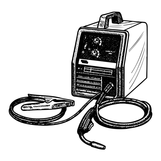
GENERAL DESCRIPTION The SP-135 PLUS is a complete semiautomatic con- stant voltage DC arc welding machine. Included is a solid state controlled, single phase constant voltage transformer/ rectifier power source and a wire feeder for feeding solid steel electrode and cored electrode. The SP-135 PLUS is ideally suited for individuals hav- ing access to 115 volt AC input power, and wanting the ease of use, quality and dependability of both gas... -
Page 16: Welding Operations
WELDING AMP RANGE WELDING AMP RANGE 25-125 25-125 SP-135 Plus FIGURE B.1a 4. Circuit Breaker – Protects machine from damage if maximum output is exceeded. Button will extend out when tripped (Manual reset). Refer to Figure B.1b. 5. Gun Trigger - Activates welding output, wire feed, and gas solenoid operation. - Page 17 FIGURE B.3 Wire Spindle Shaft To wire drive Friction Brake Adjustment With wire spool installed on the spindle shaft and the wing nut loose, turn the spool by hand while slowly tightening the wing nut until a light drag is felt. Tighten the wing nut an additional 1/4 turn.
- Page 18 FIGURE B.5 Gun Handle Gas Diffuser Contact Tip Gas Nozzle Shielding Gas When using the GMAW process, a cylinder of shield- ing gas, must be obtained. Refer to the ACCES- SORIES section for more information about selecting gas cylinders for use with the SP-135 PLUS. 1.
- Page 19 9. To stop welding, release the gun trigger and then pull the gun away from the work after the arc goes out. 10. When no more welding is to be done, close valve on gas cylinder (if used), momentarily operate gun trigger to release gas pressure, and turn off the SP-135 PLUS.
-
Page 20: Overload Protection
OPERATION OVERLOAD PROTECTION Output Overload The SP-135 PLUS is equipped with a circuit breaker which protects the machine from potential damage from excessive output current. The circuit breaker but- ton will extend out when tripped. The circuit breaker must be manually reset. Thermal Protection The SP-135 PLUS duty cycle is exceeded a thermo- stat will shut off the output until the machine cools to a... -
Page 21: Learning To Weld
LEARNING TO WELD No one can learn to weld simply by reading about it. Skill comes only with practice. The following pages will help the inexperienced operator to understand weld- ing and develop this skill. For more detailed informa- tion, order a copy of “New Lessons in Arc Welding” listed at the end of this manual. - Page 22 The “arc stream” is seen in the middle of the picture. This is the electric arc created by the electric current flowing through the space between the end of the wire electrode and the base metal. The temperature of this arc is about 6000°F, which is more than enough to melt metal.
- Page 23 B-10 For GMAW (MIG) Process 1. Is most of my welding performed on 16 gauge and lighter materials? 2. Can I afford the extra expense, space, and lack of portability required for gas cylinders and gas sup- ply? 3. Do I require clean, finished-looking welds? If you have answered yes to all the above questions GMAW may be the process for you.
- Page 24 B-11 FIGURE B.12 Penetration Unless a weld penetrates close to 100% of the metal thickness, a butt weld will be weaker than the material welded together. In the example shown in Figure B.13, the total weld is only half the thickness of the material thus the weld is only approximately half as strong as the metal.
- Page 25 B-12 PROPER GUN ANGLE PROPER GUN ANGLE FOR GMAW PROCESS FOR FCAW PROCESS WELDING IN THE VERTICAL UP POSITION WELDING IN THE VERTICAL UP POSITION FIGURE B.16 Vertical-down Welding Refer to Figure B.17 Vertical-down welds are applied at a fast pace. These welds are therefore shallow and narrow and, as such, are excellent for sheet metal.
- Page 26 B-13 FIGURE B.18 WARNING ARC RAYS can burn eyes and skin. When using an open arc process, it Is necessary to use correct eye, head and body protection. Protect yourself and others, read “ARC RAYS can burn” at the front of this manual.
- Page 27 B-14 Helpful Hints 1. For general welding, it is not necessary to weave the arc, neither forward or backward nor sideways. Weld along at a steady pace. You will find it easier. 2. When welding on thin plate, you will find that you will have to increase the welding speed, whereas when welding on heavy plate, it is necessary to go more slowly in order to get good penetration.
- Page 28 B-15 MACHINE SET UP FOR THE GMAW (MIG) PROCESS 1. See PROCESS GUIDELINES in the OPERATION section for selection of welding wire and shielding gas, and for range of metal thicknesses that can be welded. 2. See the Application Guide on the inside of wire feed section door for information on setting the controls.
- Page 29 B-16 Contact Tip Wire Electrode FIGURE B.24 3. The Correct Electrical Stickout (ESO) The electrical stickout (ESO) is the distance from the end of the contact tip to the end of the wire. See Figure B.24. Once the arc has been established, maintaining the correct ESO becomes extremely important.
-
Page 30: Troubleshooting Welds
B-17 4. After you strike the arc, practice the correct electri- cal stickout. Learn to distinguish it by its sound. 5. When you are sure that you can hold the correct electrical stickout, with a smooth “crackling” arc, start moving. Look at the molten puddle constantly. 6. - Page 31 B-18 Proper Gun Handling Most feeding problems are caused by improper han- dling of the gun cable or electrodes. 1. Do not kink or pull the gun around sharp corners 2. Keep the gun cable as straight as practical when welding.
-
Page 32: Application Chart
B-19 APPLICATION CHART B-19 SP-135 PLUS... -
Page 33: Accessories
OPTIONAL ACCESSORIES 1. K520 Utility Cart — Designed to transport the Lincoln family of small welders. Has provisions for mounting a single gas cylinder. Has front casters and large rear wheels. Handle height is easily adjustable. Bottom tray provided for tools and accessories. -
Page 34: Replacement Parts
INNERSHIELD (FCAW) CONVERSION Several changes are needed to convert the unit for operation with the Innershield (FCAW) process. The K549-1 Innershield Kit includes all the necessary accessories for this conversion and are provided for this purpose. The following conversions should be made using the contents of this kit: 1. -
Page 35: Maintenance
MAINTENANCE SAFETY PRECAUTIONS WARNING ELECTRIC SHOCK can kill. • Disconnect input power by removing plug from receptacle before working inside SP-135 PLUS. Use only grounded recep- tacle. Do not touch electrically “hot” parts inside SP-135 PLUS. • Have qualified personnel do the maintenance and trouble shoot- ing work. -
Page 36: Gun And Cable Maintenance
GUN AND CABLE MAINTENANCE FOR MAGNUM™ 100L GUN Gun Cable Cleaning Clean cable liner after using approximately 300 lbs (136 kg) of solid wire or 50 lbs (23 kg) of flux-cored wire. Remove the cable from the wire feeder and lay it out straight on the floor. -
Page 37: Component Replacement Procedures
COMPONENT REPLACEMENT PROCEDURES CHANGING THE CONTACT TIP 1. Unplug or turn power switch to Off “O” position. 2. Refer to Figure D.2. Remove the gas nozzle from the gun by unscrewing counter-clockwise. 3. Remove the existing contact tip from the gun by unscrewing counter-clockwise. -
Page 38: Changing Liner
Slotted Brass Cable Set Screw Connector Liner Assembly (Liner bushing to be seated tight against brass cable connector) FIGURE D.2 Liner trim length for gun with red trigger (Magnum™ 100L) CHANGING LINER NOTICE: The variation in cable lengths prevents the interchangeability of liners. -
Page 39: Troubleshooting
HOW TO USE TROUBLESHOOTING GUIDE Service and Repair should only be performed by Lincoln Electric Factory Trained Personnel. Unauthorized repairs performed on this equipment may result in danger to the technician and machine operator and will invalidate your factory warranty. For your safety and to avoid Electrical Shock, please observe all safety notes and precautions detailed throughout this manual. -
Page 40: Troubleshooting Guide
Fan operates normally. If for any reason you do not understand the test procedures or are unable to Perform the tests/repairs safely, contact your LOCAL AUTHORIZED LINCOLN ELECTRIC FIELD SERVICE FACILITY for assistance before you proceed. TROUBLESHOOTING POSSIBLE AREAS OF... - Page 41 If for any reason you do not understand the test procedures or are unable to Perform the tests/repairs safely, contact your LOCAL AUTHORIZED LINCOLN ELECTRIC FIELD SERVICE FACILITY for assistance before you proceed. TROUBLESHOOTING TROUBLESHOOTING GUIDE...
- Page 42 Arc is unstable – Poor starting If for any reason you do not understand the test procedures or are unable to Perform the tests/repairs safely, contact your LOCAL AUTHORIZED LINCOLN ELECTRIC FIELD SERVICE FACILITY for assistance before you proceed. TROUBLESHOOTING...
-
Page 43: Wiring Diagrams
WIRING DIAGRAMS NOTE: This diagram is for reference only. It may not be accurate for all machines covered by this manual. The specific diagram for a particular code is pasted inside the machine on one of the enclosure panels. SP-135 PLUS... - Page 44 NOTES SP-135 PLUS...
- Page 45 Address: Telephone: _______________________________________________ |_|_| |_|_| Exp Date Month BOOK DIVISION, The Lincoln Electric Company, 22801 St. Clair Avenue, Cleveland, Ohio 44117-1199 for fastest service, FAX this completed form to: 216-361-5901 Telephone: 216-383-2211 or, Titles: Price New Lessons in Arc Welding $5.00...
- Page 46 ● WARNING ● Spanish ● AVISO DE PRECAUCION ● French ● ATTENTION ● ● German WARNUNG ● Portuguese ● ATENÇÃO ● Japanese Chinese Korean Arabic READ AND UNDERSTAND THE MANUFACTURER’S INSTRUCTION FOR THIS EQUIPMENT AND THE CONSUMABLES TO BE USED AND FOLLOW YOUR EMPLOYER’S SAFETY PRACTICES. SE RECOMIENDA LEER Y ENTENDER LAS INSTRUCCIONES DEL FABRICANTE PARA EL USO DE ESTE EQUIPO Y LOS CONSUMIBLES QUE VA A UTILIZAR, SIGA LAS MEDIDAS DE SEGURIDAD DE SU SUPERVISOR.
- Page 47 ● ● Keep your head out of fumes. Turn power off before servicing. ● Use ventilation or exhaust to remove fumes from breathing zone. ● Los humos fuera de la zona de res- ● Desconectar el cable de ali- piraci n. mentaci n de poder de la m quina ●...
- Page 48 • World's Leader in Welding and Cutting Products • • Sales and Service through Subsidiaries and Distributors Worldwide • Cleveland, Ohio 44117-1199 U.S.A. TEL: 216.481.8100 FAX: 216.486.1751 WEB SITE: www.lincolnelectric.com...