Yamaha RX-V459 Service Manual
Av receiver/av amplifier
Hide thumbs
Also See for RX-V459:
- Owner's manual (93 pages) ,
- Owner's manual (111 pages) ,
- Service manual (12 pages)
Table of Contents
Advertisement
Quick Links
RX-V459/HTR-5940/DSP-AX459
This manual has been provided for the use of authorized YAMAHA Retailers and their service personnel.
It has been assumed that basic service procedures inherent to the industry, and more specifically YAMAHA Products, are already
known and understood by the users, and have therefore not been restated.
WARNING:
IMPORTANT:
The data provided is believed to be accurate and applicable to the unit(s) indicated on the cover. The research, engineering, and
service departments of YAMAHA are continually striving to improve YAMAHA products. Modifications are, therefore, inevitable
and specifications are subject to change without notice or obligation to retrofit. Should any discrepancy appear to exist, please
contact the distributor's Service Division.
WARNING:
IMPORTANT:
I CONTENTS
To Service Personnel ...................................... 2–3
Front Panels ........................................................ 3–5
Rear Panels .......................................................... 5–9
Remote Control Panels .................................... 10
Internal View ......................................................... 13
........................................ 16–37
1 0 0 9 9 8
AV RECEIVER/AV AMPLIFIER
Failure to follow appropriate service and safety procedures when servicing this product may result in personal
injury, destruction of expensive components, and failure of the product to perform as specified. For these reasons,
we advise all YAMAHA product owners that any service required should be performed by an authorized
YAMAHA Retailer or the appointed service representative.
The presentation or sale of this manual to any individual or firm does not constitute authorization, certification or
recognition of any applicable technical capabilities, or establish a principle-agent relationship of any form.
Static discharges can destroy expensive components. Discharge any static electricity your body may have
accumulated by grounding yourself to the ground buss in the unit (heavy gauge black wires connect to this buss).
Turn the unit OFF during disassembly and part replacement. Recheck all work before you apply power to the unit.
................................ 11–12
......... 14–15
........................... 38
2006
This manual is copyrighted by YAMAHA and may not be copied or
redistributed either in print or electronically without permission.
HTR-5935
SERVICE MANUAL
IMPORTANT NOTICE
Display Data ..................................................... 39–40
Ic Data ................................................................. 41–50
Pin Connection Diagram .............................. 51–52
Block Diagrams .............................................. 53–55
Printed Circuit Boards ................................ 56–68
Schematic Diagrams ...................................... 69–75
Replacement Parts List .............................. 77–95
Remote Control .............................................. 96–97
Advanced Setup .................................................... 98
All rights reserved.
P.O.Box 1, Hamamatsu, Japan
'06.02
Advertisement
Table of Contents

Related Manuals for Yamaha RX-V459


Summary of Contents for Yamaha RX-V459
-
Page 1: Service Manual
This manual has been provided for the use of authorized YAMAHA Retailers and their service personnel. It has been assumed that basic service procedures inherent to the industry, and more specifically YAMAHA Products, are already known and understood by the users, and have therefore not been restated. -
Page 2: To Service Personnel
RX-V459/HTR-5940/DSP-AX459 HTR-5935 I TO SERVICE PERSONNEL AC LEAKAGE WALL EQUIPMENT TESTER OR 1. Critical Components Information OUTLET UNDER TEST EQUIVALENT Components having special characteristics are marked s and must be replaced with parts having specifications equal to those originally installed. -
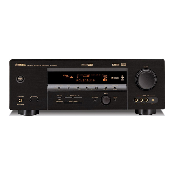
Page 3: Front Panels
I FRONT PANELS RX-V459 (U, C models) RX-V459 (R, T, K, A, G, E, L models) - Page 4 RX-V459/HTR-5940/DSP-AX459 HTR-5935 HTR-5940 (U, C models) HTR-5940 (T, K, A, G, E models) DSP-AX459 (J model)
-
Page 5: Rear Panels
RX-V459/HTR-5940/DSP-AX459 HTR-5935 HTR-5935 (U model) I REAR PANELS RX-V459 (U, C models) RX-V459 (R model) - Page 6 RX-V459/HTR-5940/DSP-AX459 HTR-5935 RX-V459 (T model) RX-V459 (K model) RX-V459 (A model)
- Page 7 RX-V459/HTR-5940/DSP-AX459 HTR-5935 RX-V459 (G, E models) RX-V459 (L model) HTR-5940 (U, C models)
- Page 8 RX-V459/HTR-5940/DSP-AX459 HTR-5935 HTR-5940 (T model) HTR-5940 (K model) HTR-5940 (A model)
- Page 9 RX-V459/HTR-5940/DSP-AX459 HTR-5935 HTR-5940 (G, E models) DSP-AX459 (J model) HTR-5935 (U model)
-
Page 10: Remote Control Panels
RX-V459/HTR-5940/DSP-AX459 HTR-5935 I REMOTE CONTROL PANELS RAV322 RAV323 RAV307 RX-V459 (R, T, K, A, G, E, L models) HTR-5940 (T, K, A, G, E models) RX-V459 (U, C models) DSP-AX459 (J model) RAV308 HTR-5940 (U, C models) HTR-5935 (U model) - Page 11 FRONT L/R SP OUT ..........150 µV or less J model ............AC 100V, 50/60 Hz [HTR-5940] Channel Separation “SILENT CINEMA” is a trademark of YAMAHA CORPORATION. Power Consumption / (1 kHz, 0.7 % THD, 8 ohms) CD, etc. (Input 5.1 k-ohms shorted, 1 kHz/10 kHz) U, C models ............
- Page 12 RX-V459/HTR-5940/DSP-AX459 HTR-5935...
-
Page 13: Internal View
RX-V459/HTR-5940/DSP-AX459 HTR-5935 I INTERNAL VIEW OPERATION (4) P.C.B. FUNCTION (2) P.C.B. FUNCTION (3) P.C.B. (R, L models) DSP P.C.B. MAIN (5) P.C.B. MAIN (4) P.C.B. OPERATION (2) P.C.B. Tuner YST P.C.B. (HTR-5935 model) FUNCTION (1) P.C.B. MAIN (1) P.C.B. FUNCTION (4) P.C.B. -
Page 14: Disassembly Procedures
RX-V459/HTR-5940/DSP-AX459 HTR-5935 I DISASSEMBLY PROCEDURES / (Remove parts in the order as numbered.) Disconnect the power cable from the AC outlet. 1. Removal of Top Cover a. Remove 4 screws (1), 5 screws (2) and 1 screw (3). (Fig. 1) b. - Page 15 Remove 5 screws (C). (Fig. 4) Fig. 5 c. Remove the FUNCTION (2) P.C.B.. (Fig. 3) When checking the P.C.B.: RX-V459/HTR-5940/DSP-AX459 models J model U, C, R, T, K, A, G, E, L models U, C models • Put a Cloth over the equipment. Put the P.C.B.s together with the Heat Sink upright on the Cloth and check them.
- Page 16 RX-V459/HTR-5940/DSP-AX459 HTR-5935 I SELF DIAGNOSIS FUNCTION (DIAG) MAIN MENU SUB MENU 9. XM Tone / 32k 10. ISO Tone / 32k This unit has self diagnosis functions that are intended for 11. XM / DT Bus Power : OFF inspection, measurement and location of faulty point.
- Page 17 RX-V459/HTR-5940/DSP-AX459 HTR-5935 • Starting DIAG Press the “STANDBY/ON” key while simultaneously pressing those two keys of the main unit as indicated in the figure below. Keys of main unit / Turn on the power while pressing these keys. • Starting DIAG in the protection cancel...
- Page 18 RX-V459/HTR-5940/DSP-AX459 HTR-5935 • Display provided when DIAG started On the FL display of the main unit, an opening message (including the version and the protection history) appears for a few seconds followed by the diagnostic menu display (1. ANALOG BYPASS).
- Page 19 RX-V459/HTR-5940/DSP-AX459 HTR-5935 The protection function worked due to the TMP PRT:000 A temperature limit being exceeded. Causes could be poor ventilation or a defect related to the thermal sensor. If the power is turned on with the abnormality unsolved, the pro- tection function works in about 1 second to turn off the power.
- Page 20 RX-V459/HTR-5940/DSP-AX459 HTR-5935 • Functions in DIAG mode In addition to the DIAG menu items, functions as listed below are available. • Input selection • Center/Rear/Rear Center/Sub-woofer level adjustment • Speaker relay control of A and B • Muting • Power on/off •...
- Page 21 RX-V459/HTR-5940/DSP-AX459 HTR-5935 • Details of DIAG menu 1. BYPASS Using the sub-menu, it is possible to select analog bypass output or DSP bypass output. ANALOG BYPASS 1.ANALOG BYPAS Reference data INPUT: DVD ANALOG SUBWOOFER OUTPUT: 50 Hz, Others: 1 kHz...
- Page 22 RX-V459/HTR-5940/DSP-AX459 HTR-5935 2. RAM THROUGH Using the sub-menu, it is possible to select margin output or full-bit output. RAM MARGIN Following head margin is reserved. FRONT CENTER SURROUND SURROUND BACK SUBWOOFER +15.0 dB +13.5 dB +9.0 dB +7.5 dB +21.0 dB 2.RAM MARGIN...
- Page 23 RX-V459/HTR-5940/DSP-AX459 HTR-5935 3. PRO LOGIC Dolby PRO LOGIC is applied to input stereo source. 3.PRO LOGIC Reference data INPUT: DVD ANALOG SUBWOOFER OUTPUT: 50 Hz, Others: 1 kHz SPEAKERS OUT SUBWOOFER Input level Volume FRONT L/R CENTER SURROUND L/R SURROUND BACK L/R OUTPUT - ∞...
- Page 24 RX-V459/HTR-5940/DSP-AX459 HTR-5935 4.FRNT:SML 0dB 4.CENTER:NONE 4.LFE/B:FRNT 4.Pres Mix:5ch 4.Front GAIN 1 4.Front GAIN 2 4.SURR B check Reference data INPUT: DVD ANALOG (Both ch) SUBWOOFER OUTPUT: 50 Hz, Others: 1 kHz SPEAKER OUT SUBWOOFER Input level Volume Sub-menu FRONT L/R...
- Page 25 RX-V459/HTR-5940/DSP-AX459 HTR-5935 5. XCH INPUT The signal input through the multi ch input is output. The speaker impedance can be selected. XCH INPUT_6 (ohms) 5.XCH INPUT_6 Reference data INPUT: MULTI CH INPUT SUBWOOFER OUTPUT: 50 Hz, Others: 1 kHz SPEAKERS OUT...
- Page 26 RX-V459/HTR-5940/DSP-AX459 HTR-5935 7. DISPLAY CHECK This program is used to check the FL display section. The display condition varies as shown below according to the sub-menu operation. The signal route is STRAIGHT. Checking FL display section / Blinking / Initial display /...
- Page 27 RX-V459/HTR-5940/DSP-AX459 HTR-5935 8. MANUAL TEST The test noise based THX is output to the channel speci- fied by the sub-menu from the DSP. The noise frequency for LFE is 35 to 250 Hz. Other than that, the center frequency is 800 Hz.
- Page 28 RX-V459/HTR-5940/DSP-AX459 HTR-5935 • PRESET STATIONS / STATION FM FACTORY PRESET DATA (MHz) STATION AM FACTORY PRESET DATA (kHz) PAGE NO. U, C R, T, K, A, G, E, L PAGE NO. U, C, R, T, K A, G, E, L 87.5...
- Page 29 RX-V459/HTR-5940/DSP-AX459 HTR-5935 IMP SW/POWER LIMIT (impedance/power limiter detection) IMP: Not applied to these models. PL: Power limiter detection value The voltage value of pin No. 92 of IC451 is dis- played, using 5V/256 as standard. The port (No. 3) output is controlled by using the in- put voltage value of pin No.
- Page 30 RX-V459/HTR-5940/DSP-AX459 HTR-5935 11. VIDEO Not applied to these models. 12. XM STATUS (U, C models) Perform the output check of XM Radio Antenna connected to the XM terminal. 1k -1dB/44.1k The test tone (1kHz, -1dB/44.1kHz) is output. 1k - 1dB/44 1k -61dB/44.1k...
- Page 31 RX-V459/HTR-5940/DSP-AX459 HTR-5935 Mute /32k Nothing is output. Mute XM Tone/32k The XM tone (32kHz) is output. Tone/32 ISO Tone/32k The ISO tone (32kHz) is output. ISO Tone/32 XM/DT Bus Power: OFF The power of XM module is turned off. Bus Power:OFF 13.
- Page 32 – OPT 1 MD/CD-R DSP-AX459 model OPT 2 OPT 3 DTV/CBL COAX 1 RX-V459/HTR-5940/HTR-5935 models COAX 2 – <2nd byte> / <3rd byte> / <4th byte> / Fs information of reproduction signal / Audio code mode information of Format information of reproduction signal /...
- Page 33 RX-V459/HTR-5940/DSP-AX459 HTR-5935 <5th byte> / Signal processing status information / Fs (kHz) bit 7 Digital mute bit 6 – bit 5 6.1 (7.1) processing bit 4 Analog mute bit 3 – bit 2 PCM through bit 1 – bit 0...
- Page 34 RX-V459/HTR-5940/DSP-AX459 HTR-5935 DGI: Digital information Not applied to these models. DGI:EE6464F95E 17. DSP BUS CHECK This menu is used to self-diagnose whether or not the bus connection for the TI (DA70Y) and the external ROM/RAM is made properly. When no error is detected, "NoEr" appears on display.
- Page 35 RX-V459/HTR-5940/DSP-AX459 HTR-5935 21. SOFT SW Note) Changing the function setting may hinder the proper operation. This menu is used to switch the function settings on P.C.B. through the software so as to activate the product. The protection function follows the P.C.B. settings. When connected to AC or in the maker preset state, the unit is initialized to the P.C.
- Page 36 RX-V459/HTR-5940/DSP-AX459 HTR-5935 ZONE2: NOT or EXIST can be selected. (SW MODE: Selectable when FNC has been selected.) 21.ZONE2:EXIST AAC: NOT or EXIST can be selected. (SW MODE: Selectable when FNC has been selected.) 21.AAC :NOT TUNER: NOT or EXIST can be selected. (SW MODE: Selectable when FNC has been selected.)
- Page 37 RX-V459/HTR-5940/DSP-AX459 HTR-5935 22. SOFTWARE VERSION The version, checksum and the port specified by the microprocessor are displayed. The signal is processed using EFFECT OFF. The checksum is obtained by adding the data at every 16 bits for each program area and expressing the result as a 4-figure hexadecimal data.
-
Page 38: Amp Adjustment
RX-V459/HTR-5940/DSP-AX459 HTR-5935 I AMP ADJUSTMENT Confirmation of Idling Current of MAIN (1) P. C. B. • Right after power is turned on, confirm that each mea- sured voltage across the terminals of R1149 (FRONT Lch), R1150 (FRONT Rch), R1153 (CENTER), R1154 (SURROUND Lch), R1152 (SURROUND Rch), R1151 (SURROUND BACK) is between 0.1 mV and 10.0 mV. -
Page 39: Display Data
RX-V459/HTR-5940/DSP-AX459 HTR-5935 RX-V459/HTR-5940/DSP-AX459 I DISPLAY DATA G V3000 : HNA-17MM03T (WG474000) G ANODE CONNECTION 13G~1G PATTERN AREA G PIN CONNECTION Pin No. 68 67 Connection F2 F2 Pin No. Connection Note : 1) Fn ..Filament pin 2) nG ..Grid pin 3) Pn .. - Page 40 RX-V459/HTR-5940/DSP-AX459 HTR-5935 HTR-5935 I DISPLAY DATA G V3000 : 17-BT-26GNK (WG473900) G ANODE CONNECTION 1G~13G PATTERN AREA G PIN CONNECTION Pin No. 68 67 Connection F2 NX Pin No. Connection Note : 1) F1, F2 ..Filament pin 2) NP ..No pin 3) NX ..
- Page 41 RX-V459/HTR-5940/DSP-AX459 HTR-5935 I IC DATA : M30625MHP-A98GP (DSP P.C.B.) Microprocessor P1_0/D8 P12_5 P0_7/AN0_7/D7 P12_6 P0_6/AN0_6/D6 P12_7 P0_5/AN0_5/D5 P5_0/WRL/WR P0_4/AN0_4/D4 P5_1/WRH/BHE P0_3/AN0_3/D3 P5_2/RD P0_2/AN0_2/D2 P5_3/BCLK P0_1/AN0_1/D1 P13_0 P0_0/AN0_0/D0 P13_1 P11_7 P13_2 P11_6 P13_3 P11_5 P5_4/HLDA M16C/62P Group (M16C/62P) P11_4 P5_5/HOLD P11_3...
- Page 42 RX-V459/HTR-5940/DSP-AX459 HTR-5935 : M30625MHP-A98GP (DSP P.C.B.) Microprocessor Port Name Terminal Name Function PowerOn Pure Direct Standby Sleep Vref Vref AD reference Avcc Avcc AD power supply P97/Adtrg/Sin4 CEFD FL Driver CE MOD0 MODEL distinction 0 P96/ANEX1/SOUT4 DTFD FL Driver TxD...
- Page 43 RX-V459/HTR-5940/DSP-AX459 HTR-5935 : M30625MHP-A98GP (DSP P.C.B.) Microprocessor Port Name Terminal Name Function PowerOn Pure Direct Standby Sleep P56/ALE FRONT A SP relay output P55/HOLD /EMP For FLASH writing (LO) P54/HLDA Protection overcurrent detection P133 Power Save P132 Power relay output...
- Page 44 RX-V459/HTR-5940/DSP-AX459 HTR-5935 : M30625MHP-A98GP (DSP P.C.B.) Microprocessor Port Name Terminal Name Function PowerOn Pure Direct Standby Sleep P05/D5 DTEV Electron volume IC DATA P04/D4 CKZ2 Zone2 Selector (BD3841) Clock (R model) P03/D3 DTZ2 Zone2 Selector (BD3841) DATA (R model) P02/D2 N.C.
- Page 45 RX-V459/HTR-5940/DSP-AX459 HTR-5935 IC56 : LC89057W-VF4-E (DSP P.C.B) Digital Audio Interface Transceiver SDIN SLRCK SBCK RDATA XMODE RLRCK DGND DVDD LC89057W-VF4-E DVDD DGND TMCK/PIO0 RBCK TBCK/PIO1 RMCK TLRCK/PIO2 AGND TDATA/PIO3 AVDD TXO/PIOE *: Pull-down resistor internal RXOUT Microcontroller Cbit, Ubit RERR...
- Page 46 RX-V459/HTR-5940/DSP-AX459 HTR-5935 IC56 : LC89057W-VF4-E (DSP P.C.B) Digital Audio Interface Transceiver Name Function 1) Input/output I or O = -0.3 to 3.6V, Is = -0.3 to 5.5V 2) Pins 32 and 33 are latch address setting input pins when pin 41 = "L".
- Page 47 RX-V459/HTR-5940/DSP-AX459 HTR-5935 IC60 : D70YE101RFP250 (DSP P.C.B) Decoder/Post Processor * No replacement part available. / SPI0_SIMO EM_CKE SPI0_SOMI/I2C0_SDA EM_CLK AXR0[0] EM_WE_DQM[1] AXR0[1] EM_D[8] AXR0[2] AXR0[3] EM_D[9] EM_D[10] AXR0[4] AXR0[5]/SPI1_SCS EM_D[11] AXR0[6]/SPI1_ENA AXR0[7]/SPI1_CLK EM_D[12] EM_D[13] EM_D[14] AXR0[8]/AXR1[5]/SPI1_SOMI EM_D[15] AXR0[9]/AXR1[4]/SPI1_SIMO EM_D[0] AXR0[10]/AXR1[3]...
- Page 48 RX-V459/HTR-5940/DSP-AX459 HTR-5935 IC60 : D70YE101RFP250 (DSP P.C.B) Decoder/Post Processor PIN NO. SIGNAL NAME TYPE PULL GPIO DESCRIPTION Ground(Vss) AHCLKX0/AHCLKX2 McASP0 and McASP2 Transmit Master Clock AMUTE0 McASP0 MUTE Output AMUTE1 McASP1 MUTE Output AHCLKX1 McASP1 Transmit Master Clock Ground(Vss) ACLKX1...
- Page 49 RX-V459/HTR-5940/DSP-AX459 HTR-5935 IC60 : D70YE101RFP250 (DSP P.C.B) Decoder/Post Processor PIN NO. SIGNAL NAME TYPE PULL GPIO DESCRIPTION EM_D[14] EMIF Data Bus [lower 16 Bits] Core Supply (CVpp) EM_D[13] EMIF Data Bus [lower 16 Bits] EM_D[12] EMIF Data Bus [lower 16 Bits]...
- Page 50 RX-V459/HTR-5940/DSP-AX459 HTR-5935 IC60 : D70YE101RFP250 (DSP P.C.B) Decoder/Post Processor PIN NO. SIGNAL NAME TYPE PULL GPIO DESCRIPTION SPI0_SOMI/I2C0_SDA SPI0 Data Pin Slave Out Master In or I2C0 Serial Data IO Supply (DVpp) AXR0[0] McASP0 Serial Data 0 Ground(Vss) AXR0[1] McASP0 Serial Data 1...
-
Page 51: Pin Connection Diagram
RX-V459/HTR-5940/DSP-AX459 HTR-5935 I PIN CONNECTION DIAGRAM • ICs BD3816K1 BD3841FS TC74HC4051AF F2602E-01 LA7106M-TLM-E TC74HC4052AF YAC523-EVR2 PCM1780DBQR TC74HC4053AF PCM1781DBQR NJM2581M PCM1803DBR BD3816K1 LA73050-TLM-E LC72722PM LC89057W-VF4A-E LM61CIZ THERMAL M30625MHP-A98GP M66003-0131FP NE5532DR OP AMP NJM2068LD NJM2388F05 5.0V NJM2068MD-TE2 NJM2388F33 NJM4556AL NJM2581M VIDEO AMP... - Page 52 RX-V459/HTR-5940/DSP-AX459 HTR-5935 SN74LV157APWR SN74LV245APWR TRAN TC4013BP FF W9816G6CH-7 SDRAM YAC520-EE2 SN74LVU04APWR TC74VHCU04FT INVER S29AL004D70TF1020 • Diodes MA8082-H 8.5V 1N4002S RB441Q-40 T-77 D2SBA20 1.5A 200V MA8030-L 2.9V RB500V-40 1SS133,176 RB441Q-40 T-77 D5SB20 5A 200V MA8051-M 5.1V RB501V-40 1SS270A MA8056-M 5.6V UDZ 3.6BTE-17 3.6V...
- Page 53 AXR1[3] 20, 19 SL/SR DASL/DASR *VDD=5V SL/SR IC52 IC74 RX-V459, AXR0[0] DASB U, C models HTR-5940, HTR-5935 models DSP-AX459 model RX-V459, DSP-AX459, HTR-5940 models 8ch DAC RXOUT MD/CD-R PCM1680 IC68 Selector SN74LV157APWR 16M SDRAM 4M ROM IC67 IC64 IC66 XMDT...
- Page 54 RX-V459/DSP-AX459/HTR-5935 VIDEO BLOCK DIAGRAM OUTPUT AMP LA73050 BYPASS IC401 CVBS INPUT SELECTOR 74HC4051 • See page 73 → CVBS DVR OUT DTV/CBL OPERATION SCHEMATIC DIAGRAM CVBS IC402 RX-V459, V-AUX DSP-AX459, HTR-5940 models CVBS DTV/CBL IC403 RX-V459, IC404 DSP-AX459, RX-V459, HTR-5940...
- Page 55 RX-V459/DSP-AX459/HTR-5935 CONTROL/POWER BLOCK DIAGRAM POWER • See page 69-71 → TRANSFORMER /4ohms SCHEMATIC DIAGRAM RY105 OPERATION • See page 73 → SCHEMATIC DIAGRAM LIMITER CONTROL IR REMOTE RY105 U3000 POWER RELAY 51/ 50/ 49/ 48/ 46 SPEAKER RELAY VOLUME 63/ 64...
- Page 56 RX-V459/DSP-AX459/HTR-5935 I PRINTED CIRCUIT BOARDS FUNCTION (1) FUNCTION (1) (CB200) (CB202) DSP P.C.B. (Side A) Lead Free Solder Used MD/CD-R MD/CD-R SDTN SCKN /CES /VSY SVIDD BYPASS /ICCNV /INTCNV /VR1 /MON CPNTD COMP0 COMP1 CBYPASS /CNONE DTV/CBL CKFD DTFD CEFD/MOD0...
- Page 57 RX-V459/DSP-AX459/HTR-5935 DSP P.C.B. (Side B) Lead Free Solder Used • Semiconductor Location Ref no. Location Ref no. Location...
- Page 58 RX-V459/DSP-AX459/HTR-5935 (CB56) (CB1) FUNCTION (1) P.C.B. (Side A) WOOFER CENTER/ WOOFER OPERATION (1) (W3002) SURROUND FRONT (REC) (PLAY) AUX-V OPERATION (5) (W3007) OPERATION (2) (W2501) DTV/CBL • Semiconductor Location Ref no. Location Ref no. Location D2003 Q2007 D2004 Q2008 to TUNER...
- Page 59 RX-V459/DSP-AX459/HTR-5935 FUNCTION (1) P.C.B. (Side B) Lead Free Solder Used 65 64 24 25 • Semiconductor Location Ref no. Location Ref no. Location D2000 Q2003 D2001 Q2004 D2002 Q2009 D2005 Q2011 D2006 Q2012 IC200 Q2013 IC201 Q2014 IC202 Q2015 IC205...
- Page 60 RX-V459/DSP-AX459/HTR-5935 COMPONENT VIDEO U, C, R, T, K, A, G, E, L models D4 VIDEO DTV/CBL MONITOR OUT MONITOR DTV/CBL FUNCTION (2) P.C.B. (Side A) J model /MON /VR1 /INTCNV /ICCNV BYPASS SVIDD /VSY /CES SCKN SDTN OPERATION (2) (CB252) (CB2) FUNCTION (3) P.C.B.
- Page 61 RX-V459/DSP-AX459/HTR-5935 FUNCTION (2) P.C.B. (Side B) Lead Free Solder Used • Semiconductor Location Ref no. Location Ref no. Location D2851 D2863 D2852 D2864 D2853 D2865 D2854 D2866 D2855 D2867 D2856 IC286 D2857 IC287 D2858 IC288 D2859 IC289 D2860 IC290 D2861...
- Page 62 RX-V459/DSP-AX459/HTR-5935 OPERATION (1) P.C.B. (Side A) (CB5) to TRANSFORMER STANDBY TUNING MODE MEMORY PRESET/TUNING/CH A/B/C/D/E FM/AM PRESET/TUNING – AUTO/MAN'L MAN'L/AUTO FM LEVEL NEXT EDIT PROGRAM STRAIGHT SPEAKERS EFFECT BASS/TREBLE – MULTI CH INPUT INPUT MODE INPUT TONE CONTROL FUNCTION (1)
- Page 63 RX-V459/DSP-AX459/HTR-5935 OPERATION (1) P.C.B. (Side B) Lead Free Solder Used 33 32 RX-V459/HTR-5940/ DSP-AX459 models 64 1 HTR-5935 model OPERATION (3) P.C.B. (Side B) Lead Free Solder Used • Semiconductor Location Ref no. Location Ref no. Location D3001 IC301 D3002...
- Page 64 RX-V459/DSP-AX459/HTR-5935 OPERATION (2) P.C.B. OPERATION (2) P.C.B. (Side A) (Side B) Lead Free Solder Used RX-V459/HTR-5940/DSP-AX459 models VIDEO S VIDEO DTV/CBL MONITOR DTV/CBL MONITOR RX-V459/HTR-5940/DSP-AX459 models HTR-5935 model RX-V459/HTR-5940/ DSP-AX459 models RX-V459/HTR-5940/DSP-AX459 models FUNCTION (1) (CB201) MAIN (2) /MON (W1006)
- Page 65 RX-V459/DSP-AX459/HTR-5935 OPERATION (4) P.C.B. OPERATION (4) P.C.B. (Side A) (Side B) Lead Free Solder Used U, C, T, K, A, B, G, J models AC IN to POWER TRANSFORMER R, L models FUNCTION (3) (W3005A, W3005B) AC OUTLETS MAIN (1)
- Page 66 O: USED/APPLICABLE Q1007 Q1073 Q1008 Q1074 Circuit No. RX-V459 model/DSP-AX459 model HTR-5935 model Circuit No. RX-V459 model/DSP-AX459 model HTR-5935 model MAIN (3) Q1009 Q1075 MAIN (5) C1003, 1013, 1014, 1024, 1032, 1037 R1002, 1008, 1013, 1020, 1029, 1033, (CB116) Q1010...
- Page 67 RX-V459/DSP-AX459/HTR-5935 MAIN (2) P.C.B. (Side A) Lead Free Solder Used MAIN (1) (W1002A) MAIN (1) OPERATION (2) (W1001A) (CB251) MAIN (1) (W1000A) IGND XGND +5.3X XMPWR +3.3D (CB57) PRV2 MAIN (4) P.C.B. MAIN (5) P.C.B. (Side A) Lead Free Solder Used...
- Page 68 RX-V459/DSP-AX459/HTR-5935 HTR-5935 YST P.C.B. (Side A) Lead Free Solder Used YST_LIM PRI_SW NFSW YST+ SWOUT YST- MAIN (1) (CB101) • Semiconductor Location Ref no. Location Ref no. Location D5000 Q5003 D5001 Q5004 Q5005 D5002 Q5006 D5003 Q5007 IC500 Q5008 Q5000...
- Page 69 RX-V459/HTR-5940/HTR-5935/DSP-AX459 SCHEMATIC DIAGRAMS DSP 1/3 POINT A-1 Pin 18 of IC2 POINT B-2 1 / Pin7, 2 / Pin8 of CB3 POWER ON (connect the power cable) -11.9 IC1 : RH5RE58AA-T1-FA Voltage regulator – -11.9 Vref -11.9 MICRO PROCESSOR IC4, 5 : SN74AHCT1G32DCKR...
- Page 70 RX-V459/HTR-5940/HTR-5935/DSP-AX459 DSP 2/3 IC61, 62 : SN74AHCT1G32DCKR IC63 : SN74AHCT08PWR Single 2-input positive-OR gate Quadruple 2-input positive-AND gates POINT A-1 Pin 28 of IC55 POINT A-2 Pin 29 of IC56 IC64 : W9816G6CH -7 512K x 2 banks x 16 bits SDRAM...
- Page 71 RX-V459/HTR-5940/HTR-5935/DSP-AX459 DSP 3/3 Page 72 Page 74 to FUNCTION (1)_CB202 to MAIN (2)_W1004 IC71-74, 75, 76 : NJM4565M Dual operational amplifier 2, 6 –INPUT OUTPUT 1, 7 +INPUT 3, 5 V– LC89057W-VF4A-E LC89057W-VF4AD-E ANALOG IN IC70 : PCM1803DBR Stereo A/D converter 11.8...
- Page 72 RX-V459/HTR-5940/HTR-5935/DSP-AX459 FUNCTION Page 71 Page 73 Page 69 to DSP_CB56 to OPERATION (5)_W3007 to DSP_CB1 -6.9 EXTENSION SELECTOR Page 69 Page 73 IC200 : BD3816K1 to DSP_CB2 to OPERATION (2)_CB252 7-channel volume IC for 7-channel LOGIC AGND1 VINFR INA1 GOUTFL...
- Page 73 FUNCTION (3)_W3005A,W3005B VIN1 +VCC1 +Vcc DCCNT1 VOUT1 Page 74 Page 72 Page 72 to MAIN (2)_W1006 to FUNCTION (2)_CB290 to FUNCTION (1)_CB201 VIN2 VOUT2 RX-V459/DSP-AX459 models MUTE1 N.C. VIN3 VOUT3 RX-V459/DSP-AX459 models N.C. -VCC1 220K N.C. -VCC2 N.C. N.C. VIN4...
- Page 74 -57.2 -60.1 Low dropout voltage regulator with ON/OFF control Page 72 -57.2 -57.7 to FUNCTION (1)_CB207 -58.3 Vout 58.8 59.9 58.2 59.9 no use(RX-V459/DSP-AX459 models) Page 72 59.6 58.2 59.3 Bandgrap 4.7/50 -0.4 Reference to FUNCTION (1)_CB206 -1.0 -0.6 ON/OFF -0.6...
- Page 75 RX-V459/HTR-5940/HTR-5935/DSP-AX459 HTR-5935 SUBWOOFER IC500 : NJM2068LD Dual operational-amplifier 2, 6 OUTPUT –INPUT 1, 7 +INPUT 3, 5 V– # All voltages are measured with a 10MΩ/V DC electronic volt meter. # Components having special characteristics are marked s and must be replaced with parts having specifications equal to those originally installed.
-
Page 76: Replacement Parts List
RX-V459/HTR-5940/DSP-AX459 HTR-5935 I REPLACEMENT PARTS LIST • ELECTRICAL COMPONENT PARTS WARNING G Components having special characteristics are marked s and must be replaced with parts having specifications equal to those originally installed. ABBREVIATIONS IN THIS LIST ARE AS FOLLOWS: C.A.EL.CHP : CHIP ALUMI.ELECTROLYTIC CAP... - Page 77 RX-V459/HTR-5940/DSP-AX459 HTR-5935 P.C.B. DSP ✻ New Parts...
- Page 78 RX-V459/HTR-5940/DSP-AX459 HTR-5935 P.C.B. DSP ✻ New Parts...
- Page 79 RX-V459/HTR-5940/DSP-AX459 HTR-5935 P.C.B. DSP ✻ New Parts...
- Page 80 RX-V459/HTR-5940/DSP-AX459 HTR-5935 P.C.B. DSP & P.C.B. FUNCTION ✻ New Parts...
- Page 81 RX-V459/HTR-5940/DSP-AX459 HTR-5935 P.C.B. FUNCTION ✻ New Parts...
- Page 82 RX-V459/HTR-5940/DSP-AX459 HTR-5935 P.C.B. FUNCTION ✻ New Parts...
- Page 83 RX-V459/HTR-5940/DSP-AX459 HTR-5935 P.C.B. FUNCTION & P.C.B. OPERATION ✻ New Parts...
- Page 84 RX-V459/HTR-5940/DSP-AX459 HTR-5935 P.C.B. OPERATION ✻ New Parts...
- Page 85 RX-V459/HTR-5940/DSP-AX459 HTR-5935 P.C.B. OPERATION ✻ New Parts...
- Page 86 RX-V459/HTR-5940/DSP-AX459 HTR-5935 P.C.B. OPERATION & P.C.B. MAIN ✻ New Parts...
- Page 87 RX-V459/HTR-5940/DSP-AX459 HTR-5935 P.C.B. MAIN ✻ New Parts...
- Page 88 RX-V459/HTR-5940/DSP-AX459 HTR-5935 P.C.B. MAIN ✻ New Parts...
- Page 89 RX-V459/HTR-5940/DSP-AX459 HTR-5935 P.C.B. MAIN ✻ New Parts...
- Page 90 RX-V459/HTR-5940/DSP-AX459 HTR-5935 P.C.B. MAIN & P.C.B. YST Chip Resistors The chip resistor is not supplied as a replacement part. * When a chip resistor is necessary, use the following part. AAX60720: CHIP RESISTOR SAMPLE BOOK ✻ New Parts ✻ New Parts...
- Page 91 RX-V459/HTR-5940/DSP-AX459 HTR-5935 • OVERALL ASS’Y U, C models HTR-5935 model RX-V459/HTR-5940/ DSP-AX459 models 6 (2) K model 6 (1) 7 (4) 201-1 200-1 R, L models J, U, C, R, T, L models K, A, G, E models 7 (2)
- Page 92 RX-V459/HTR-5940/DSP-AX459 HTR-5935 • OVERALL ASS’Y ✻ New Parts ✻ New Parts...
- Page 93 RX-V459/HTR-5940/DSP-AX459 HTR-5935 • FRONT PANEL UNIT • FRONT PANEL UNIT 1-25 1-25 1-25 7 (1) 1-25 1-25 1-25 1-25 1-25 7 (3) 1-25 7 (6) 1-40 1-13 7 (5) 1-25 ✻ New Parts...
- Page 94 RX-V459/HTR-5940/DSP-AX459 HTR-5935 • AMP UNIT • AMP UNIT 2-104 2-20 2-104 2-1 (2) 2-1 (5) 2-1 (4) 2-106 2-1 (1) 2-105 HTR-5935 model 2-103 2-105 2-11 2-104 2-104 ✻ New Parts...
- Page 95 RX-V459/HTR-5940/DSP-AX459 HTR-5935 I REMOTE CONTROL RAV322: RX-V459 (U, C models), HTR-5940 (U, C models) RAV323: DSP-AX459 (J model) • SCHEMATIC DIAGRAM • PANELS • KEY LAYOUT • KEY CODE RAV322 YAMAHA UNIVERSAL FORMAT : NEC FORMAT CARRIER FREQ. : 37.9 kHz...
- Page 96 RX-V459/HTR-5940/DSP-AX459 HTR-5935 I REMOTE CONTROL RAV307: RX-V459 (R, T, K, A, G, E, L models), HTR-5940 (T, K, A, G, E models) RAV308: HTR-5935 (U model) • SCHEMATIC DIAGRAM • KEY CODE CODE Function CD-R TUNER PORTABLE 0 ohm TV POWER –...
- Page 97 RX-V459/HTR-5940/DSP-AX459 HTR-5935...
- Page 98 RX-V459/HTR-5940/DSP-AX459 HTR-5935 I REPLACEMENT PARTS LIST FOR CARBON RESISTORS Value 1/4W Type Part No. 1/6W Type Part No. Value 1/4W Type Part No. 1/6W Type Part No. 1.0 Ω 3100 3100 10 kΩ 7100 7100 HJ35 HF85 HF45 HF45 1.8 Ω...
- Page 99 RX-V459/HTR-5940/DSP-AX459 HTR-5935...