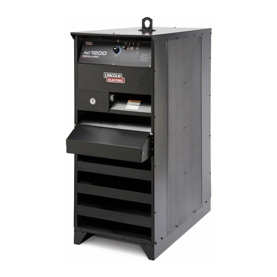
Lincoln Electric IDEALARC AC-1200 User Manual
Single phase variable voltage power source for automatic ac welding
Hide thumbs
Also See for IDEALARC AC-1200:
- Technical specifications (2 pages) ,
- Specification sheet (168 pages) ,
- Operator's manual (25 pages)
Table of Contents
Advertisement
Quick Links
RETURN TO MAIN MENU
IM283-C
®
IDEALARC AC- 1200
October, 2010
Single Phase Variable Voltage Power Source For Automatic AC Welding
For use with machines having Code Numbers 10291C, 10292C, 10465 and 10466.
Safety Depends on You
Lincoln arc welding and cutting
equipment is designed and built
with safety in mind. However,
your overall safety can be
increased by proper installation ...
and thoughtful operation on your
part. DO NOT INSTALL, OPER-
ATE OR REPAIR THIS EQUIP-
MENT WITHOUT READING
THIS MANUAL AND THE
Safety Precautions CON-
TAINED THROUGHOUT. And,
most importantly, think before you
act and be careful.
OPERATOR'S MANUAL
Copyright © Lincoln Global Inc.
• World's Leader in Welding and Cutting Products •
• Sales and Service through Subsidiaries and Distributors Worldwide •
Cleveland, Ohio 44117-1199 U.S.A. TEL: 216.481.8100 FAX: 216.486.1751 WEB SITE: www.lincolnelectric.com
Advertisement
Table of Contents

Related Manuals for Lincoln Electric IDEALARC AC-1200


Summary of Contents for Lincoln Electric IDEALARC AC-1200
- Page 1 RETURN TO MAIN MENU IM283-C ® IDEALARC AC- 1200 October, 2010 Single Phase Variable Voltage Power Source For Automatic AC Welding For use with machines having Code Numbers 10291C, 10292C, 10465 and 10466. Safety Depends on You Lincoln arc welding and cutting equipment is designed and built with safety in mind.
-
Page 2: California Proposition 65 Warnings
351040, Miami, Florida 33135 or CSA Standard W117.2-1974. A Free copy of “Arc Welding Safety” booklet E205 is available from the Lincoln Electric Company, 22801 St. Clair Avenue, Cleveland, Ohio 44117-1199. bE SURE THAT ALL INSTALLATION, OPERATION, MAINTENANCE AND REPAIR PROCEDURES ARE PERFORMED ONLY bY QUALIFIED INDIVIDUALS. - Page 5 PRÉCAUTIONS DE SÛRETÉ Pour votre propre protection lire et observer toutes les instructions et les précautions de sûreté specifiques qui parraissent dans ce manuel aussi bien que les précautions de sûreté générales suiv- antes: Sûreté Pour Soudage A L’Arc 1. Protegez-vous contre la secousse électrique: a.
- Page 6 Thank You...
-
Page 7: Table Of Contents
Installation...Section A Location ...A-1 Input Wiring ...A-1 Output Connections...A-1 a. Wire Feeder Connections ...A-1 Ratings: ...A-1 Connection of AC-1200 (with NL Option) to LAF or LT34 ...A-2 Connection of AC-1200 to NA-4 with Switch for ‘Current Control’ ...A-2 Connection of AC-1200 to NA-4 with rheostat for current control or LT-6...A-2 b. -
Page 8: Location
LOCATION Install the welder in a dry location where there is free circu- lation of air in through the louvers in front and out through the louvers in the back of the case. A location which mini- mizes the amount of smoke and dirt drawn into the machine reduces the chance of dirt accumulation that can block air passages and cause overheating. -
Page 9: Connection Of Ac-1200 To Na-4 With Switch For 'Current Control
Connection of AC-1200 to NA-4 with rheostat for current control or LT-6. INSTALLATION Connection of AC-1200 to NA-4 with Switch for ‘Current Control’ IDEALARC® AC-1200 S 15667 4 18 75 S 15602 6 22 84H... -
Page 10: B. Output Studs
b. Output Studs Connect the work cables to the ‘To Work’ stud on the front of the Ac-1200. Connect the electrode cables to the ‘Min,’ ‘Med’ or ‘Max’ studs for the output desired. Actual current ranges for each stud are indicated on the name- plate above each stud. -
Page 11: Safety Precautions
SAFETY PRECAUTIONS Read and understand this entire section before oper- ating the machine. WARNING ELECTRIC SHOCK can kill. • Do not touch electrically live parts or electrode with skin or wet clothing. • Insulate yourself from work and ground. • Always wear dry insulating gloves. -
Page 12: Safety Precautions
SAFETY PRECAUTIONS WARNING ELECTRIC SHOCK can kill. • Have qualified personnel do the mainte- nance and troubleshooting work. • Turn the input power OFF at the disconnect switch or fuse box before working on this equipment. • Do not touch electrically live parts or electrode with skin or wet clothing. -
Page 13: How To Use Troubleshooting Guide
HOW TO USE TROUbLESHOOTING GUIDE Service and Repair should only be performed by Lincoln Electric Factory Trained Personnel. Unauthorized repairs performed on this equipment may result in danger to the technician and machine operator and will invalidate your factory warranty. For your safety and to avoid Electrical Shock, please observe all safety notes and precautions detailed throughout this manual. -
Page 14: Troubleshooting
Observe all Safety Guidelines detailed throughout this manual PRObLEMS (SYMPTOMS) Welder will not start. Welder will not weld (Contactors operating properly) Welder will not weld (Contactors not operating). Welder welds at min. only no control. If for any reason you do not understand the test procedures or are unable to perform the tests/repairs safely, contact your Local Lincoln Authorized Field Service Facility for technical troubleshooting assistance before you proceed. - Page 15 PRObLEMS (SYMPTOMS) Welder welds at max. only no con- trol. Contacts chatter. If for any reason you do not understand the test procedures or are unable to perform the tests/repairs safely, contact your Local Lincoln Authorized Field Service Facility for technical troubleshooting assistance before you proceed. TROUbLESHOOTING POSSIbLE CAUSE...
- Page 16 DIAGRAMS IDEALARC® AC-1200...
- Page 17 AC-1200 SCOTT CONNECTION DIAGRAM I f u s i n g t h e 9 0 1 . U s e a p h a s e m e t e r . 9 0 V A C 2 . U s e a n o s c i l l o s c o p e . t h e p h a s e s e q u e n c e u s e o n e o f t h e f o l l o w i n g m e t h o d s .
- Page 18 DIAGRAMS AC-1200 SCOTT CONNECTION DIAGRAM IDEALARC® AC-1200...
- Page 19 DIAGRAMS AC-1200 AND PARALLELED DC-1000’s IDEALARC® AC-1200...
- Page 20 DIAGRAMS AC-1200 AND DC-1500’s IDEALARC® AC-1200...
- Page 21 DIAGRAMS AC-1200 WIRING DIAGRAM (With NL Option) NOTE: This diagram is for reference only. It is not accurate for all machines covered by this manual. The specific diagram for a particular code is pasted inside the machine on one of the enclosure panels. If the diagram is illegi- ble, write to the Service Department for a replacement.
- Page 22 NOTES IDEALARC® AC-1200...
- Page 23 NOTES IDEALARC® AC-1200...
- Page 24 NOTES IDEALARC® AC-1200...
- Page 27 • World's Leader in Welding and Cutting Products • • Sales and Service through Subsidiaries and Distributors Worldwide • Cleveland, Ohio 44117-1199 U.S.A. TEL: 216.481.8100 FAX: 216.486.1751 WEB SITE: www.lincolnelectric.com...