Table of Contents
Advertisement
Safety Depends on You
Lincoln arc welding and cutting
equipment is designed and built
with safety in mind. However, your
overall safety can be increased by
proper installation ... and thought-
ful operation on your part. DO
NOT INSTALL, OPERATE OR
REPAIR THIS EQUIPMENT
WITHOUT
READING
THIS
MANUAL AND THE SAFETY
PRECAUTIONS CONTAINED
THROUGHOUT. And, most
importantly, think before you act
and be careful.
Date of Purchase:
Serial Number:
Code Number:
Model:
Where Purchased:
• Sales and Service through Subsidiaries and Distributors Worldwide •
Cleveland, Ohio 44117-1199 U.S.A. TEL: 216.481.8100 FAX: 216.486.1751 WEB SITE: www.lincolnelectric.com
RETURN TO MAIN MENU
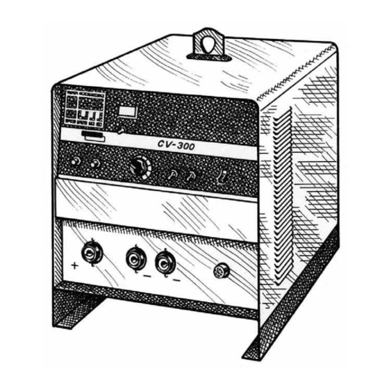
IDEALARC CV-300
For use with machine Code Numbers 10180, 10181
OPERATOR'S MANUAL
• World's Leader in Welding and Cutting Products •
®
Copyright © 2002 Lincoln Global Inc.
IM500-A
October, 2002
Advertisement
Table of Contents
Troubleshooting

Related Manuals for Lincoln Electric IDEALARC CV-300


Summary of Contents for Lincoln Electric IDEALARC CV-300
- Page 1 IDEALARC CV-300 For use with machine Code Numbers 10180, 10181 Safety Depends on You Lincoln arc welding and cutting equipment is designed and built with safety in mind. However, your overall safety can be increased by proper installation ... and thought- ful operation on your part.
-
Page 2: California Proposition 65 Warnings
351040, Miami, Florida 33135 or CSA Standard W117.2-1974. A Free copy of “Arc Welding Safety” booklet E205 is available from the Lincoln Electric Company, 22801 St. Clair Avenue, Cleveland, Ohio 44117-1199. BE SURE THAT ALL INSTALLATION, OPERATION, MAINTENANCE AND REPAIR PROCEDURES ARE PERFORMED ONLY BY QUALIFIED INDIVIDUALS. - Page 3 ELECTRIC SHOCK can kill. 3.a. The electrode and work (or ground) circuits are electrically “hot” when the welder is on. Do not touch these “hot” parts with your bare skin or wet clothing. Wear dry, hole-free gloves to insulate hands. 3.b.
-
Page 4: Iii Safety
WELDING SPARKS can cause fire or explosion. 6.a. Remove fire hazards from the welding area. If this is not possible, cover them to prevent the welding sparks from starting a fire. Remember that welding sparks and hot materials from welding can easily go through small cracks and openings to adjacent areas. - Page 5 PRÉCAUTIONS DE SÛRETÉ Pour votre propre protection lire et observer toutes les instruc- tions et les précautions de sûreté specifiques qui parraissent dans ce manuel aussi bien que les précautions de sûreté générales suivantes: Sûreté Pour Soudage A L’Arc 1. Protegez-vous contre la secousse électrique: a.
- Page 6 This statement appears where the information must be followed to avoid minor personal injury or damage to this equipment. for selecting a QUALITY product by Lincoln Electric. We want you to take pride in operating this Lincoln Electric Company product •••...
-
Page 7: Table Of Contents
TABLE OF CONTENTS Installation ...Section A Technical Specifications ...A-1 Select Suitable Location ...A-2 Input Connections...A-2 Field Installed Options ...A-3 Required Equipment - Control Cable Connections...A-3 Output Connections..A-3 Paralleling ...A-4 Connection of Auxiliary Equipment to Wire Feeder Receptacle ...A-4 Operation ...Section B Safety Precautions ...B-1 General Description ...B-2 Recommended Processes and Equipment ...B-2... -
Page 8: Installation
TECHNICAL SPECIFICATIONS – IDEALARC CV-300 Standard Voltage 208/230/460/3/60 230/460/575/3/60 Duty Cycle 100% Duty Cycle NEMA Class I (100) 60% Duty Cycle 100% Duty Cycle Welding Current/Voltage Range (Continuous) 50A/7V - 400A/37V Efficiency at 100% Load Idle Power 800W Height 21.5 in. -
Page 9: Select Suitable Location
• Do not touch electrically hot parts. • Always connect the Idealarc CV-300 grounding terminal (located on the welder base near the reconnect panel) to a good electrical earth ground. -
Page 10: Field Installed Options
FIELD INSTALLED OPTIONS For installation of compatible field installed options (see the ACCESSORIES section of this manual and refer to the instructions included with those options. REQUIRED EQUIPMENT-CONTROL CABLE CONNECTIONS Follow the instructions below which are appropriate for the wire feeder that will be used. LN-7 to CV-300 a) Turn the CV-300 Power switch to the "OFF"... -
Page 11: Paralleling
PARALLELING The CV-300 is not designed to be paralleled with any other power source. CONNECTION OF AUXILIARY EQUIPMENT TO THE WIRE FEEDER RECEPTACLE Occasionally, it may be necessary to make connection to the circuits present in the 14-pin wire feeder recep- tacle. -
Page 12: Operation
OPERATING INSTRUCTIONS Read and understand this entire section before oper- ating the machine. GENERAL WARNINGS SAFETY PRECAUTIONS Observe additional Safety Guidelines detailed throughout this manual. OPERATION WARNING ELECTRIC SHOCK can kill. • Do not touch electrically live parts or electrode with skin or wet clothing. -
Page 13: General Description
CAUTION When using a CV-300 power source with wire feed- ers, there will be a small spark if the electrode con- tacts the work or ground within several seconds after releasing the trigger. When used with some wire feeders with the electrical trigger interlock in the ON position, the arc might restart if the electrode touches the work or ground during these several seconds. -
Page 14: Controls And Settings
CONTROLS AND SETTINGS All operator controls and adjustments are located on the case front of the CV-300. Refer to Figures B.1, and B.2 and corresponding explanations. A. POWER SWITCH B. VOLTAGE ADJUSTMENT C. THERMAL PROTECTION INDICATION LIGHT D. VOLTS / AMPS SWITCH E. -
Page 15: Graphic Symbols
J. WIRE FEEDER VOLTMETER SWITCH -This switch selects the polarity of the wire feeder voltmeter, if so equipped. When weld- ing electrode positive (MIG, Outershield and some Innershield processes) set the switch to "+". GRAPHIC SYMBOLS THAT APPEAR ON THIS MACHINE OR IN THIS MANUAL POWER REMOTE OUTPUT VOLTAGE CONTROL... -
Page 16: Output Panel Connections
OUTPUT PANEL CONNECTIONS A. POSITIVE OUTPUT CONNECTION B. LOW INDUCTANCE NEG. CONNECTION A., B., C. OUTPUT CONNECTORS -Each connector is a Magnum Twist-Mate™, receptacle. Insert a mating Twist-Mate™ plug, and twist clockwise to secure. For GMAW processes, and most FCAW processes, the positive output connection goes to the wire feeder. -
Page 17: Starting The Machine
STARTING THE MACHINE The power switch at the extreme right side of the con- trol panel energizes the CV-300. ADJUSTING THE OUTPUT VOLTAGE USING THE DIGITAL METER The digital meters in the CV-300 incorporate a voltage pre- set function. This allows the operator to set the desired welding voltage before striking an arc. -
Page 18: Accessories
FACTORY INSTALLED OPTIONS/ACCESSORIES There are no factory installed options/accessories on the CV-300. FIELD INSTALLED OPTIONS REMOTE VOLTAGE CONTROL (K857) The K857 consists of a control box with 25 feet (7.6 m) of four conductor cable. Installation of a K857 Remote Voltage Control in the CV-300 requires a K864 Remote Control Adapter. -
Page 19: Maintenance
SAFETY PRECAUTIONS WARNING ELECTRIC SHOCK can kill. • Only qualified personnel should perform this maintenance. • Turn the input power OFF at the disconnect switch or fuse box before working on this equipment. • Do not touch electrically hot parts. GENERAL MAINTENANCE 1. -
Page 20: Troubleshooting
HOW TO USE TROUBLESHOOTING GUIDE Service and Repair should only be performed by Lincoln Electric Factory Trained Personnel. Unauthorized repairs performed on this equipment may result in danger to the technician and machine operator and will invalidate your factory warranty. For your safety and to avoid Electrical Shock, please observe all safety notes and precautions detailed throughout this manual. -
Page 21: Built-In Diagnostic Routines/Error Codes
Observe all Safety Guidelines detailed throughout this manual BUILT-IN DIAGNOSTIC ROUTINES AND ERROR CODES The CV-300 Meter PC Board displays error codes when certain trouble conditions exist. The error codes, trouble conditions, and possible remedies are listed below. ERROR TROUBLE CODE 1. -
Page 22: Machine Troubleshooting Guide
Observe all Safety Guidelines detailed throughout this manual MACHINE TROUBLESHOOTING GUIDE Not all trouble conditions can be recognized by the PC board, and displayed as error codes. The following guide covers most other trouble conditions. PROBLEMS (SYMPTOMS) Machine has no output. Machine has minimum output and no control. - Page 23 Observe all Safety Guidelines detailed throughout this manual PROBLEMS (SYMPTOMS) Thermal Protection Indicator light is Machine does not have maximum output Machine will not shut off. Variable or sluggish welding arc. Digital meters do not light - or - Digital meter display is incorrect. If for any reason you do not understand the test procedures or are unable to perform the tests/repairs safely, contact your Local Lincoln Authorized Field Service Facility for technical troubleshooting assistance before you proceed.
- Page 24 Observe all Safety Guidelines detailed throughout this manual PROBLEMS (SYMPTOMS) Output Control not functioning on the machine. Poor arc striking with semiautomatic wire feeders. Poor arc characteristics If for any reason you do not understand the test procedures or are unable to perform the tests/repairs safely, contact your Local Lincoln Authorized Field Service Facility for technical troubleshooting assistance before you proceed.
-
Page 25: Options Troubleshooting Guide
Observe all Safety Guidelines detailed throughout this manual OPTIONS TROUBLESHOOTING GUIDE K857 (or other) Remote Output Control PROBLEMS (SYMPTOMS) Output control not functioning on Remote Control. Voltage Adjust not functioning on the machine. If for any reason you do not understand the test procedures or are unable to perform the tests/repairs safely, contact your Local Lincoln Authorized Field Service Facility for technical troubleshooting assistance before you proceed. -
Page 26: Procedure For Replacing Pc Boards
If there is damage to the PC board or if replacing PC board corrects problem, return it to the local Lincoln Electric Field Service Shop. If for any reason you do not understand the test procedures or are unable to perform the tests/repairs safely, contact your Local Lincoln Authorized Field Service Facility for technical troubleshooting assistance before you proceed. - Page 27 OUTPUT VOLTAGE The open circuit voltage of the machine should be 10 to 43 volts. If any other condition exists, refer to the Troubleshooting Guide. FAULT PROTECTION OPERATION The overload protection circuit on the PC Board will cause the CV-300 meter to display "E60". This pro- tection circuit will reset itself automatically.
-
Page 28: Diagrams
DIAGRAMS 224A CV-300... - Page 29 DIAGRAMS CV POWER SOURCE TO AN LN-7 AND K857 CV-300...
- Page 30 DIAGRAMS CV POWER SOURCE TO A K867 UNIVERSAL ADAPTER CV-300...
- Page 31 DIAGRAMS CV POWER SOURCE TO A K867 / K775 / LN-7 CV-300...
- Page 32 DIAGRAMS CV POWER SOURCE TO AN LN-25 CV-300...
- Page 33 DIAGRAMS CV POWER SOURCE TO AN LN-25 / K444-1 CV-300...
- Page 34 DIAGRAMS LINCOLN POWER SOURCE TO AN LN-742 CV-300...
- Page 35 DIAGRAMS K867 UNIVERSAL ADAPTER INSTALLATION AND CONNECTION INSTRUCTIONS CV-300...
- Page 36 TWIST-MATE CABLE PLUG INSTALLATION INSTRUCTIONS TWIST-MATE WELDING CABLE PLUG INSTALLATION INSTRUCTIONS TURN THE POWER SWITCH OF THE WELDING POWER SOURCE "OFF" BEFORE INSTALLING PLUGS ON CABLES OR WHEN CONNECTING OR DISCONNECTING PLUGS TO WELDING POWER SOURCE. CHECK THAT THE CONNECTOR BOOT IS MARKED FOR THE APPROPRIATE CABLE SIZE PER TABLE BELOW;...
- Page 37 F-10 F-10 DIAGRAMS CONNECTION OF NON-LINCOLN WIRE FEEDERS CV-300...
- Page 38 F-11 F-11 DIAGRAMS DIMENSION PRINT CV-300...
- Page 39 NOTES CV-300...
- Page 40 NOTES CV-300...
- Page 41 Address: Telephone: _______________________________________________ |_|_| |_|_| Exp Date Month BOOK DIVISION, The Lincoln Electric Company, 22801 St. Clair Avenue, Cleveland, Ohio 44117-1199 for fastest service, FAX this completed form to: 216-361-5901 Telephone: 216-383-2211 or, Titles: Price New Lessons in Arc Welding $5.00...
- Page 42 ● WARNING ● Spanish ● AVISO DE PRECAUCION ● French ● ATTENTION ● German ● WARNUNG ● Portuguese ● ATENÇÃO ● Japanese Chinese Korean Arabic ● ● ● ● ● ● ● ● ● ●...
- Page 43 ● ● ● ● ● ● ● ● ● ● ● ● ● ● ● ● ● ● Spanish ● PRECAUCION French ● ATTENTION German ● WARNUNG Portuguese ● ● Japanese Chinese Korean Arabic WARNING AVISO DE ATENÇÃO...
- Page 44 • World's Leader in Welding and Cutting Products • • Sales and Service through Subsidiaries and Distributors Worldwide • Cleveland, Ohio 44117-1199 U.S.A. TEL: 216.481.8100 FAX: 216.486.1751 WEB SITE: www.lincolnelectric.com...