Table of Contents
Advertisement
RETURN TO MAIN MENU
IM736-D
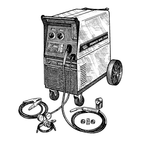
POWER MIG
300
™
February, 2004
For use with machine Code Numbers: 10562, 10952, 10958, 11000, 11097, 11098
For use with machine
Safety Depends on You
Lincoln arc welding and cutting
equipment is designed and built
with safety in mind. However, your
overall safety can be increased by
proper installation ... and thought-
ful operation on your part. DO
NOT INSTALL, OPERATE OR
REPAIR THIS EQUIPMENT
WITHOUT
READING
THIS
MANUAL AND THE SAFETY
PRECAUTIONS CONTAINED
THROUGHOUT. And, most
importantly, think before you act
and be careful.
OPERATOR'S MANUAL
Copyright © 2004 Lincoln Global Inc.
• World's Leader in Welding and Cutting Products •
• Sales and Service through Subsidiaries and Distributors Worldwide •
Cleveland, Ohio 44117-1199 U.S.A. TEL: 216.481.8100 FAX: 216.486.1751 WEB SITE: www.lincolnelectric.com
Advertisement
Table of Contents
Troubleshooting

Related Manuals for Lincoln Electric POWER MIG IM736-D


Summary of Contents for Lincoln Electric POWER MIG IM736-D
- Page 1 RETURN TO MAIN MENU IM736-D POWER MIG ™ February, 2004 For use with machine Code Numbers: 10562, 10952, 10958, 11000, 11097, 11098 For use with machine Safety Depends on You Lincoln arc welding and cutting equipment is designed and built with safety in mind.
-
Page 2: California Proposition 65 Warnings
351040, Miami, Florida 33135 or CSA Standard W117.2-1974. A Free copy of “Arc Welding Safety” booklet E205 is available from the Lincoln Electric Company, 22801 St. Clair Avenue, Cleveland, Ohio 44117-1199. BE SURE THAT ALL INSTALLATION, OPERATION, MAINTENANCE AND REPAIR PROCEDURES ARE PERFORMED ONLY BY QUALIFIED INDIVIDUALS. -
Page 3: Electric Shock Can Kill
ELECTRIC SHOCK can kill. 3.a. The electrode and work (or ground) circuits are electrically “hot” when the welder is on. Do not touch these “hot” parts with your bare skin or wet clothing. Wear dry, hole-free gloves to insulate hands. - Page 4 WELDING SPARKS can cause fire or explosion. 6.a. Remove fire hazards from the welding area. If this is not possible, cover them to prevent the welding sparks from starting a fire. Remember that welding sparks and hot materials from welding can easily go through small cracks and openings to adjacent areas.
- Page 5 PRÉCAUTIONS DE SÛRETÉ Pour votre propre protection lire et observer toutes les instructions et les précautions de sûreté specifiques qui parraissent dans ce manuel aussi bien que les précautions de sûreté générales suiv- antes: Sûreté Pour Soudage A L’Arc 1. Protegez-vous contre la secousse électrique: a.
- Page 6 The code number is especially important when identifying the correct replacement parts. - Register your machine with Lincoln Electric either via fax or over the Internet. • For faxing: Complete the form on the back of the warranty statement included in the literature packet accompanying this machine and fax the form per the instructions printed on it.
-
Page 7: Table Of Contents
________________________________________________________________________ Installation...Section A Technical Specifications...A-1 Safety Precautions ...A-2 Uncrating the POWER MIG 300...A-2 Location...A-2 Input Power, Grounding and Connection Diagrams ...A-2, A-3 Gun and Cable Installation ...A-4 Shielding Gas ...A-4 thru A-5 ________________________________________________________________________________ Operation...Section B Safety Precautions ...B-1 Definition Of Welding Modes...B-1 Common Welding Abbreviations ...B-1 Product Description ...B-2 Controls and Settings ...B-2, B-3... -
Page 8: Installation
TECHNICAL SPECIFICATIONS – POWER MIG 300 Standard Voltage/Frequency 208/230/460/575/60 Hz Input Voltage Duty Cycle 230/460/575 208/230/460/575 100% Welding Current Range (Continuous) Maximum Open Circuit Voltage 5 – 350 Amps RECOMMENDED INPUT WIRE AND FUSE SIZES - SINGLE PHASE Input Voltage/ 230Amps @ Frequency (Hz) 29 Volts... -
Page 9: Safety Precautions
Roll the machine off the skid assembly. LOCATION Locate the welder in a dry location where there is free circulation of clean air into the louvers in the back and out the front. A location that minimizes the amount of... - Page 10 A green wire in the input cable connects this contact to the frame of the welder. This ensures proper grounding of the welder frame when the welder plug is inserted into the receptacle. INSTALLATION FIGURE A.2 — Receptacle Diagram...
-
Page 11: Gun And Cable Installation
.035-.045" (0.9-1.2 mm) electrode and contact tips for .035” (0.9mm) and .045” (1.2mm) are included for 15Ft.. WARNING Turn the welder power switch off before installing gun and cable. LINER INSTALLATION AND TRIMMING INSTRUCTION (SEE FIGURE A.3) 1. Remove the gas nozzle. - Page 12 DO NOT ATTACH THE REGULATOR IF OIL, GREASE OR DAMAGE IS PRESENT! Inform your gas supplier of this condition. Oil or grease in the presence of high pressure oxygen is explosive. 3. Stand to one side away from the outlet and open the cylinder valve for an instant.
-
Page 13: Operation
Read entire Operation section before operating the POWER MIG 300. WARNING ELECTRIC SHOCK can kill. • Do not touch electrically live parts or electrode with skin or wet clothing. Insulate yourself from work and ground. • Always wear dry insulating gloves. -
Page 14: Product Description
PRODUCT DESCRIPTION The POWER MIG 300 is a complete semiautomatic multi-process DC arc welding machine offering CV and CC DC welding. It is rated for 300 amps, 32 volts at a 60% duty cycle. The standard machine is equipped to weld CC-Stick, CC-GTAW, CV-FCAW, and synergic and non-synergic CV-GMAW / GMAW-P and Pulse-on-Pulse and Power Mode welding processes. - Page 15 2. VOLT / TRIM METER - This meter displays either the voltage or trim value depending on the status of the machine. Located below the display is the text "Volts" and "Trim." An LED light is illuminated to the left of one of these in order to indicate the units of the value displayed in the meter.
-
Page 16: Setting And Configuring The Power Mig 300 For Welding
SETTING AND CONFIGURING THE POWER MIG 300 FOR WELDING • Check that the electrode polarity is correct for the process • Toggle the SET switch to the desired "Weld Mode" opera- • Toggle the SELECT switch to activate the "weld parame- •... -
Page 17: Multi-Process Panel Functions
MULTI-PROCESS PANEL FUNCTIONS Weld Mode Setting the Weld Mode is selecting the proper program from the ones available in the machine’s memory for a particular welding application. The table on the right side of the front panel (See Figure B.2) gives information on the different programs available in this machine. - Page 18 Arc Control (See Table B.2) There are no specific unit values offered because the setting of this feature largely depends upon operator preference. Arc Control has a different effect on the character of the arc depending upon the welding process applied. In SMAW (STICK mode), arc control adjusts the arc force.
-
Page 19: Wire Drive Roll
In the case of special waveforms designed for pulsed weld- ing aluminum, Pulse on Pulse™, the effect is similar to what occurs with standard pulse. As the Arc Control is increased from +1 to +10 the frequency of the Pulse on Pulse array increases. -
Page 20: Procedure For Changing Drive And Idle Roll Sets
PROCEDURE FOR CHANGING DRIVE AND IDLE ROLL SETS 1. Turn off the power source. 2. Release the pressure on the idle roll by swinging the adjustable pressure arm down toward the back of the machine. Lift the cast idle roll assembly and allow it to sit in an upright position. -
Page 21: Feeding Wire Electrode
OPERATION 1. Press end of gun against a solid object that is elec- trically isolated from the welder output and press the gun trigger for several seconds. 2. If the wire “birdnests”, jams or breaks at the drive roll, the idle roll pressure is too great. -
Page 22: Special Welding Processes Available
B-10 SPECIAL WELDING PROCESSES AVAILABLE ON THE POWER MIG 300 PULSE WELDING (GMAW-P) The pulsed-arc process is, by definition, a spray trans- fer process wherein spray transfer occurs in pulses at regularly spaced intervals. In the time between pulses, the welding current is reduced and no metal transfer occurs. - Page 23 Arc Control can be used to vary the ripple spacing in the weld bead. BENEFITS OF PULSE ON PULSE FROM LINCOLN ELECTRIC • Excellent appearance of the weld bead • Improved cleaning action • Reduced porosity Table B.3 shows WFS and Trim settings for common...
-
Page 24: Power Mode
B-12 POWER MODE™ The Power Mode™ process was developed by Lincoln to maintain a stable and smooth arc at low procedure settings which are needed to weld thin metal without pop-outs or burning-through. For Aluminum welding, it provides excellent control and the ability to maintain constant arc length. -
Page 25: Accessories
DRIVE ROLL KITS Refer to Table C.1 for various drive roll kits that are available for the POWER MIG. All items in Bold are supplied standard with the POWER MIG. TABLE C.1 Wire Size .023”-.030” (0.6-0.8 mm) Solid .035” (0.9 mm) Steel .045”... -
Page 26: Push-Pull Feeding Connection Adapter Kit
ADAPTER KIT (K2154-1) The push-pull adapter kit provides direct connection of a Cobra Gold or Prince XL torch to the wire feeder welder. The kit is intended for use with the following Cobra Gold or Prince XL torches: Arc Voltage... -
Page 27: Maintenance
GENERAL MAINTENANCE In extremely dusty locations, dirt may clog the air pas- sages causing the welder to run hot. Blow dirt out of the welder with low-pressure air at regular intervals to eliminate excessive dirt and dust build-up on internal parts. -
Page 28: Liner Removal And Replacement
CAUTION Excessive pressure at the start may cause the dirt to form a plug. Flex the cable over its entire length and again blow out the cable. Repeat this procedure until no further dirt comes out. If this has been done and feed prob- lems are experienced, try liner replacement, and refer to trouble shooting section on rough wire feeding. - Page 29 Service and Repair should only be performed by Lincoln Electric Factory Trained Personnel. Unauthorized repairs performed on this equipment may result in danger to the technician and machine operator and will invalidate your factory warranty. For your safety and to avoid Electrical Shock, please observe all safety notes and precautions detailed throughout this manual.
-
Page 30: Troubleshooting
Local Lincoln Authorized Field Service Facility for technical troubleshooting assistance before you proceed. TROUBLESHOOTING POSSIBLE AREAS OF MISADJUSTMENT(S) 1. Contact your local authorized Lincoln Electric Field Service facility for technical assistance. 1. Make certain that the fuses or breakers are properly sized. See installation section of the manual for recommended fuse and breaker sizes. -
Page 31: Troubleshooting
If for any reason you do not understand the test procedures or are unable to perform the tests/repairs safely, contact your LOCAL AUTHORIZED LINCOLN ELECTRIC FIELD SERVICE FACILITY for assistance before you proceed. TROUBLESHOOTING POSSIBLE AREAS OF... - Page 32 If for any reason you do not understand the test procedures or are unable to perform the tests/repairs safely, contact your LOCAL AUTHORIZED LINCOLN ELECTRIC FIELD SERVICE FACILITY for assistance before you proceed. TROUBLESHOOTING POSSIBLE AREAS OF...
- Page 33 Gas does not flow when gun trigger is pulled. If for any reason you do not understand the test procedures or are unable to perform the tests/repairs safely, contact your LOCAL AUTHORIZED LINCOLN ELECTRIC FIELD SERVICE FACILITY for assistance before you proceed. TROUBLESHOOTING POSSIBLE AREAS OF...
-
Page 34: Fault Codes
Observe all Safety Guidelines detailed throughout this manual Code Description Glitch on the primary over current fault interrupt; possibly caused by noise or a signal level (misc. hardware fault #1) Main CPU problem. The DSP has detected a problem with the CPU. Glitch on the CAP/heart beat interrupt;... - Page 35 Observe all Safety Guidelines detailed throughout this manual PROBLEMS (SYMPTOMS) PUSH PULL WIRE FEEDING PROBLEMS While loading wire, the rear drive rolls stop while pushing wire through the torch. While loading wire, the wire bird nests before the wire gets all the way through the torch.
- Page 36 Observe all Safety Guidelines detailed throughout this manual PROBLEMS (SYMPTOMS) PUSH PULL WIRE FEEDING PROBLEMS While loading wire the wire bird nests if the wire misses the outlet guide while shooting the gap in the torch. Arc length varies while welding (arc length is not constant).
- Page 37 Observe all Safety Guidelines detailed throughout this manual PROBLEMS (SYMPTOMS) PUSH PULL WIRE FEEDING PROBLEMS During Welding the wire continues to burn back to the tip. Wire bird nests while welding. If for any reason you do not understand the test procedures or are unable to perform the tests/repairs safely, contact your Local Lincoln Authorized Field Service Facility for technical troubleshooting assistance before you proceed.
- Page 38 If for any reason you do not understand the test procedures or are unable to perform the tests/repairs safely, contact your Local Lincoln Authorized Field Service Facility for technical troubleshooting assistance before you proceed. TROUBLESHOOTING that allows the welder to adjust the maximum amount of POWER MIG 300 CAUTION...
-
Page 39: Diagrams
WIRING DIAGRAMS POWER MIG 300 ENHANCED DIAGRAM J324 J323 J321... - Page 40 WIRING DIAGRAMS POWER MIG 300 J324 J323 J321...
- Page 41 WIRING DIAGRAMS POWER MIG 300...
- Page 42 WIRING DIAGRAM POWER MIG 300 ENHANCED DIAGRAM J811...
- Page 43 DIMENSION PRINT POWER MIG 300...
- Page 44 NOTES POWER MIG 300...
- Page 45 NOTES POWER MIG 300...
- Page 46 ● WARNING ● Spanish ● AVISO DE PRECAUCION ● French ● ATTENTION ● ● German WARNUNG ● Portuguese ● ATENÇÃO ● Japanese Chinese Korean Arabic ● ● ● ● ● ● ● ● ● ●...
- Page 47 ● ● ● ● ● ● ● ● ● ● ● ● ● ● ● ● ● ● Spanish ● PRECAUCION French ● ATTENTION ● German WARNUNG Portuguese ● ● Japanese Chinese Korean Arabic WARNING AVISO DE ATENÇÃO...
- Page 48 • World's Leader in Welding and Cutting Products • • Sales and Service through Subsidiaries and Distributors Worldwide • Cleveland, Ohio 44117-1199 U.S.A. TEL: 216.481.8100 FAX: 216.486.1751 WEB SITE: www.lincolnelectric.com...