Table of Contents
Advertisement
RETURN TO MAIN INDEX
SVM132-A
May, 2002
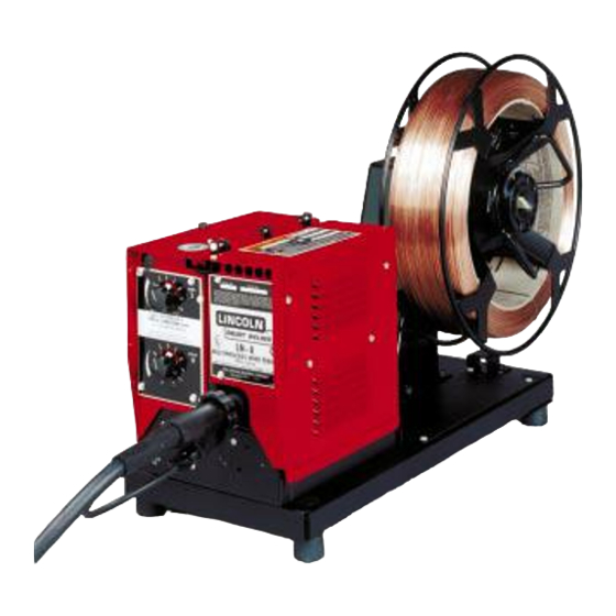
LN-8 SEMIAUTOMATIC WIRE FEEDER
For use with code numbers: 9963, 9964
Safety Depends on You
Lincoln arc welding and cutting
equipment is designed and built
with safety in mind. However, your
overall safety can be increased by
proper installation ... and thought-
ful operation on your part. DO
NOT INSTALL, OPERATE OR
REPAIR THIS EQUIPMENT
WITHOUT
READING
THIS
MANUAL AND THE SAFETY
PRECAUTIONS CONTAINED
THROUGHOUT. And, most
importantly, think before you act
and be careful.
SERVICE MANUAL
Copyright © 2002 Lincoln Global Inc.
• World's Leader in Welding and Cutting Products •
• Sales and Service through Subsidiaries and Distributors Worldwide •
Cleveland, Ohio 44117-1199 U.S.A. TEL: 216.481.8100 FAX: 216.486.1751 WEB SITE: www.lincolnelectric.com
Advertisement
Chapters
Table of Contents
Troubleshooting

Related Manuals for Lincoln Electric LN-8 SVM132-A


Summary of Contents for Lincoln Electric LN-8 SVM132-A
-
Page 1: Service Manual
RETURN TO MAIN INDEX SVM132-A May, 2002 LN-8 SEMIAUTOMATIC WIRE FEEDER For use with code numbers: 9963, 9964 Safety Depends on You Lincoln arc welding and cutting equipment is designed and built with safety in mind. However, your overall safety can be increased by proper installation ... -
Page 2: Safety
351040, Miami, Florida 33135 or CSA Standard W117.2-1974. A Free copy of “Arc Welding Safety” booklet E205 is available from the Lincoln Electric Company, 22801 St. Clair Avenue, Cleveland, Ohio 44117-1199. BE SURE THAT ALL INSTALLATION, OPERATION, MAINTENANCE AND REPAIR PROCEDURES ARE PERFORMED ONLY BY QUALIFIED INDIVIDUALS. -
Page 3: Electric Shock Can Kill
ELECTRIC SHOCK can kill. 3.a. The electrode and work (or ground) circuits are electrically “hot” when the welder is on. Do not touch these “hot” parts with your bare skin or wet clothing. Wear dry, hole-free gloves to insulate hands. - Page 4 WELDING SPARKS can cause fire or explosion. 6.a. Remove fire hazards from the welding area. If this is not possible, cover them to prevent the welding sparks from starting a fire. Remember that welding sparks and hot materials from welding can easily go through small cracks and openings to adjacent areas.
- Page 5 PRÉCAUTIONS DE SÛRETÉ Pour votre propre protection lire et observer toutes les instruc- tions et les précautions de sûreté specifiques qui parraissent dans ce manuel aussi bien que les précautions de sûreté générales suivantes: Sûreté Pour Soudage A L’Arc 1. Protegez-vous contre la secousse électrique: a.
-
Page 6: Table Of Contents
MASTER TABLE OF CONTENTS FOR ALL SECTIONS Safety ............Installation . - Page 7 LN-8 for Opposite Polarity Operation ....... . . For Power Sources Other Than Lincoln Electric ......
-
Page 8: Technical Specifications
TECHNICAL SPECIFICATIONS – LN-8 50 in. to 600 in. per minute (1.25 to 15.24 m/min) ELECTRODE SOLID CORED OPERATING STORAGE LENGTH LN-8 WITH K303 30.25 in. (50-60 lb wire reel stand (768 mm) with dust cover over reel) LN-8 WITH K377 22.19 in. -
Page 9: Mounting Location
Use the type of power source required for the specific welding application. CAUTION Never operate a Lincoln Squirt welder wire feeder with a power source that has a jumper from #2 to #4 on the terminal strip, or with a power source without a contactor. -
Page 10: Ln-8S And Ln-8Se (And Converted Ln-8N And Ln-8Ne)
LN-8S AND LN-8SE (AND CONVERTED LN-8N AND LN-8NE) 1. Use either a constant voltage or constant current type power source as required for the application. Ensure the power source is properly set for constant voltage or constant current welding, as appropriate, per the instructions in the power source operating manual. -
Page 11: Power Source Connection Diagrams
Connection of LN-8 to an Idealarc® R3S-400, 600 or 800 (with LVC) (Discontinued) Connection of LN-8 to an Idealarc R3S-400, 600 or 800 (without LVC) (Discontinued) Connection of LN-8 to a SAM Motor-Generator or Engine Driven Welder Connection of LN-8 to R3S-250 and R3S-325... -
Page 12: (With Lvc) (Discontinued)
FIGURE A.2 – CONNECTION OF LN-8 TO AN IDEALARC R3S-400, 600 OR 800 N.A. NEGATIVE N.B. POWER SOURCE THE ABOVE DIAGRAM SHOWS THE ELECTRODE CONNECTED FOR POSITIVE POLARITY. TO CHANGE POLARITY, TURN OFF THE POWER, REVERSE THE ELECTRODE AND "TO WORK" LEADS AT THE POWER SOURCE, AND REVERSE THE "CONTROL SWITCH" AT THE POWER SOURCE. -
Page 13: (Without Lvc) (Discontinued)
FIGURE A.3 – CONNECTION OF LN-8 TO AN IDEALARC R3S-400, 600 OR 800 WARNING ELECTRIC CAN KILL N.A. NEGATIVE N.B. POWER SOURCE THE ABOVE DIAGRAM SHOWS THE ELECTRODE CONNECTED FOR POSITIVE POLARITY. TO CHANGE POLARITY, TURN OFF THE POWER, REVERSE THE ELECTRODE AND "TO WORK" LEADS AT THE POWER SOURCE, AND REVERSE THE "CONTROL SWITCH" AT THE POWER SOURCE. -
Page 14: Connection Of Ln-8 To A Sam Motor-Generator Or Engine Driven Welder
FIGURE A.4 – CONNECTION OF LN-8 TO A SAM MOTOR-GENERATOR OR ENGINE DRIVEN WELDER REMOVE SAM PORTABLE FIELD CONTROL AND CONNECT LEADS B AND C FROM LN-8 CONTROL CABLE. DO NOT CONNECT LEAD A. LEAD MUST BE TAPED UP. AUTO EQUIP. -
Page 15: Connection Of Ln-8 To R3S-250 And R3S-325
FIGURE A.5 – CONNECTION OF LN-8 TO R3S-250 AND R3S-325 POWER SOURCE NEGATIVE THE ABOVE DIAGRAM SHOWS THE ELECTRODE CONNECTED FOR POSITIVE POLARITY. TO CHANGE POLARITY, TURN OFF THE POWER, REVERSE THE ELECTRODE AND "TO WORK" LEADS AT THE POWER SOURCE, AND REVERSE THE 'CONTROL SWITCH' AT THE POWER SOURCE. -
Page 16: Connection Of Ln-8 To
A-10 FIGURE A.6 – CONNECTION OF LN-8 TO DC-600 POWER SOURCE NEGATIVE THE ABOVE DIAGRAM SHOWS THE ELECTRODE CONNECTED POSITIVE. TO CHANGE POLARITY, TURN OFF THE POWER, REVERSE THE ELECTRODE AND "TO WORK" LEADS AT THE POWER SOURCE, AND POSITION THE SWITCH ON THE POWER SOURCE TO PROPER POLARITY. -
Page 17: Connection Of Ln-8 To Dc-250, 400 And Cv/Cvi Power Sources
A-11 FIGURE A.7 – CONNECTION OF LN-8 TO DC-250, 400 AND CV/CVI POWER SOURCES POWER SOURCE CV OUTPUT TERMINALS ON DC-250 NEGATIVE N.A. THE ABOVE DIAGRAM SHOWS THE ELECTRODE CONNECTED POSITIVE. TO CHANGE POLARITY, TURN OFF THE POWER, REVERSE THE ELECTRODE AND "TO WORK"... -
Page 18: To Ln-8 For Same Polarity Operation
INSTALLATION TURN OFF INPUT POWER TO THE WELDING POWER SOURCE USING THE DISCONNECT SWITCH BEFORE WORKING ON THIS EQUIPMENT. N.B.B. N.B.B. N.C. N.B. WELDER CONTROL CABLE WIRE FEEDER CONTROL CABLE N.A. TO "A" WIRE FEEDER CLEVELAND, OHIO U.S.A. LN-8 A-12... -
Page 19: To Ln-8 For Opposite Polarity Operation
TO THE WELDING POWER SOURCE USING THE DISCONNECT SWITCH BEFORE WORKING ON THIS EQUIPMENT. N.B.B. N.B.B. N.A. N.C. N.B. WELDER CONTROL CABLE WIRE FEEDER CONTROL CABLE N.A. TO "A" WIRE FEEDER ELECTRODE NEGATIVE NEAR THE POWER SOURCE TERMINAL STRIP OR CLEVELAND, OHIO U.S.A. -
Page 20: For Power Sources Other Than Lincoln Electric
A-14 FIGURE A.10 – FOR POWER SOURCES OTHER THAN LINCOLN ELECTRIC POWER SOURCE INTERNALLY POWERED CONTACTOR OUTPUT CONTACTOR COIL FOR POWER TO OPERATE CONTACTOR MAX. RATING OR LN-8 #2 TO #4 CIRCUIT IS 5 AMP 115 VAC OR 5 AMP 28 VDC... -
Page 21: Input Cable Connections
A-15 INPUT CABLE CONNECTIONS For connecting an LN-8 to a specific Lincoln Electric power source, use the appropriate steps in one of these paragraphs and refer to the connection dia- grams listed on Table A.2 for the applicable power source. Table A.2 lists each figure number with its corresponding power source. - Page 22 A-16 FIGURE A.12 – INPUT CONTROL CABLE AND ELECTRODE CABLE EXTENSIONS WIRE DRIVE UNIT CONTROL CABLE EXTENSION ELECTRODE EXTENSION 2. The standard cable setup consists of an electrode cable and a control cable with a polarized plug on the wire feeder end. Position the control cable with the polarized plug at the wire reel base.
- Page 23 A-17 9. Remove the ingoing guide tube from the rear brass block of the wire feeder and plug the connector of the electrode cable extension into the brass block. Tighten the locking screw with a 3/16 in. Allen wrench. The guide tube is not used when the extension assembly is installed.
-
Page 24: Gun And Cable Assemblies
A-18 GUN AND CABLE ASSEMBLIES GENERAL The LN-8 is used with various guns. In all cases, the gun is shipped connected to the cable and is ready to weld. Use the gun recommended for the wire type (solid or cored) and size to be used. See the para- graph on Welding Guns in the Accessories Section for more information on the different types of guns. - Page 25 SECTION B-1 Operation ..............Section B Safety Instructions .
-
Page 26: Safety Instructions
Read and understand this entire section before operating your machine. SAFETY INSTRUCTIONS WARNING ELECTRIC SHOCK can kill. • Do not touch electrically live parts such as output terminals or internal wiring. • Insulate yourself from the work and ground. • Always wear dry insulating gloves. ____________________________________ FUMES AND GASES can be dangerous. -
Page 27: Constant Voltage Controls
CURRENT CONTROL. Adjusts welding current by controlling power source output. VOLTAGE CONTROL. Adjusts arc voltage by control- ling wire feed speed. TRIGGER INTERLOCK. With the switch in the OFF position, the wire feed motor runs and the welding cir- cuit is energized only when the gun trigger is pressed. The operator must hold the trigger in from the start to the finish of the weld. -
Page 28: Circuit Protection
CIRCUIT PROTECTION FIELD CIRCUIT FUSE. This 1/2 amp slow blow fuse, located on the Relay PC board, protects the field cir- cuit. It will blow if the field shorts or if one of the field circuit components on the Relay PC board fails. MOTOR THERMAL PROTECTION. -
Page 29: Wire Feed Rolls And Guide Tubes
WIRE FEED ROLLS AND GUIDE TUBES The drive rolls and guide tube kits are ordered sepa- rately. Refer to Figure B.3 and install these parts per the following instructions: 1. Loosen the idle roll spring pressure screw. 2. Remove the drive roll screw and clamping collar from the drive shaft. -
Page 30: Setting For Cv Or Cc Power Sources
7. Install the large ingoing guide into the rear brass block and tighten the locking screw. 8. Install the outgoing guide tube with its plastic insert through the front brass block. Tighten the locking screw so the dog point goes into the groove on the O.D. -
Page 31: Welding With A Constant Voltage Power Source
FIGURE B.4 – CV-CC SWITCH CV-CC SWITCH VARIABLE VOLTAGE PC BOARD VARIABLE PC BOARD WELDING WITH A CONSTANT VOLTAGE POWER SOURCE 1. Current and voltage adjustments Amps Control — All Power Sources Set the welding current (or wire feed speed) with the LN-8 Amps control. -
Page 32: Wire Reel Loading - 50 And 60 Lb. Coils (K303 Wire Reel Stand
WIRE REEL LOADING – 50 AND 60 lb COILS (K303 WIRE REEL STAND) MOUNTING A 50 OR 60 lb COIL 1. To remove the wire reel from its shaft, grasp the spring loaded knob and pull out. This straightens the knob so it seats into the shaft when released. Remove the reel. -
Page 33: Wire Reel Loading (K1524-1 Unversal Wire Reel Stand
WIRE REEL LOADING (K1524-1 UNIVERSAL WIRE REEL STAND) TO MOUNT A 30 lb (14 kg) READI-REEL PACKAGE (USING THE MOLDED PLASTIC K363-P READI-REEL ADAPTER): The spindle should be located in the LOWER mount- ing hole. 1. Depress the Release Bar on the Retaining Collar and remove it from the spindle. - Page 34 B-10 TO MOUNT 10 TO 44 lb (4.5 to 20 kg) SPOOLS (12 in./300 mm DIAMETER) OR 14 lb (6 kg) INNERSHIELD COILS: The spindle should be located in the lower mounting hole. [For 8 in. (200 mm) spools, a K468 spindle adapter must first be slipped onto the spindle.] [For 13 to 14 lb (6 kg) Innershield coils, a K435 Coil Adapter must be used.]...
-
Page 35: Feeding Electrode To The Ln-8N Or Ln-8S
B-11 FEEDING ELECTRODE TO THE LN-8N OR LN-8S 1. Turn the reel until the free end of the electrode is accessible. 2. While tightly holding the electrode, cut off the bent end and straighten the first six inches. Cut off the first inch. (If the electrode is not properly straightened, it may not feed or may not go into the outgoing guide tube causing a “birdnest”.) 3. -
Page 36: Slow Acceleration Starting (Code 7926 And Above
B-12 SLOW ACCELERATION STARTING (CODE 7926 AND ABOVE) The LN-8 has the capability of optimum starting for dif- ferent processes. This is accomplished by designing the LN-8 to start with two different speeds of con- trolled acceleration. As shipped, the unit is connected for fast acceleration, which is best for most open arc procedures. - Page 37 SECTION C-1 Accessories... Section C General... K163 Undercarriage (Requires K303, K377, or K378) ... K178 Mounting Platform ... K261 Meter Kit... K202 Burnback Kit... K58 Magnetic Separator ... K119 Gravity Feed Flux Cone ... K310 Flux Screen ... K320 Flux Tank ... K161 Mechanized Travel Power Pack...
-
Page 38: General
GENERAL The following is a list of the accessories that can be used with the LN-8 wire feeder unit. TABLE C.1 – LN-8 WIRE FEEDER ACCESSORIES Product Number Name K163 UNDERCARRIAGE K178 MOUNTING PLATFORM K261 METER KIT K202 BURNBACK KIT MAGNETIC SEPARATOR K119 GRAVITY FEED FLUX CONE... -
Page 39: K58 Magnetic Separator
K163 UNDERCARRIAGE (REQUIRES K303, K377, OR K378) The undercarriage includes casters, wheels, a handle, and related hardware. Casters are mounted at the front and wheels are mounted at the rear of the plat- form. The handle is bolted to the front of the platform so the wire feeder can be tilted back and wheeled like a two-wheel truck. -
Page 40: Reel Mounting Accessories
K240 CONTACTOR KIT Output contactor with pilot relay to make the electrode ‘cold’ when not welding. Must be ordered when using the LN-8 with SA-750, SAE, TM, R3M and R3R Idealarcs. Contactor kits are rated at 600 amps maxi- mum, and cannot be paralleled with each other. K317 DUAL PROCESS KIT (NO POLARITY CHANGE) The Dual Process Kit is a transfer device that con-... -
Page 41: Welding Guns
The Squirtmobile is a self-propelled trackless carriage that carries the K114 sub-arc gun on long welds for automatic welder economy without high fixture costs. To use the LN-8S or LN-8SE with the Squirtmobile, install the K161 mechanized travel power pack. - Page 42 NOTES LN-8...
-
Page 43: Routine Maintenance
SECTION D-1 Maintenance ............. . Section D Routine Maintenance . -
Page 44: Routine Maintenance
ROUTINE MAINTENANCE DRIVE ROLLS AND GUIDE TUBES After feeding every coil of wire, inspect the drive roll section. Clean the assembly as necessary. Do not use solvent to clean the drive roll assembly as it may wash the lubricant out of the bearings. The drive rolls and guide tubes are stamped with the wire sizes they will feed. - Page 45 SECTION E-1 THEORY OF OPERATION -THEORY OF OPERATION SECTION- Theory of Operation ............Section E General Description .
-
Page 46: General Description
THEORY OF OPERATION FIGURE E.1 – POWER INPUT CIRCUITS REMOTE OUTPUT CONTROL WIRE FEED SPEED CONTROL CIRCUIT BREAKER INPUT RECEPTACLE & 2 OHMS #531 CONTROL OPTIONAL BURNBACK BOARD GENERAL DESCRIPTION The LN-8 is a semiautomatic wire feeder designed for Innershield (FCAW) and gas metal arc processes with the appro- priate accessories. -
Page 47: Gun Trigger And 1Cr Relay Contact Control Circuits
THEORY OF OPERATION FIGURE E.2 – GUN TRIGGER AND 1CR CONTACT CONTROL CIRCUITS REMOTE OUTPUT CONTROL WIRE FEED SPEED CONTROL CIRCUIT BREAKER INPUT RECEPTACLE & 2 OHMS #531 CONTROL OPTIONAL BURNBACK BOARD GUN TRIGGER AND 1CR RELAY CONTACT CONTROL CIRCUITS When the gun trigger switch is activat- ed (closed) the 1CR relay is energized. -
Page 48: Variable Voltage Board, Meter Shunt, Wire Speed
THEORY OF OPERATION FIGURE E.3 – VARIABLE VOLTAGE BOARD, METER SHUNT, WIRE SPEED, REMOTE OUTPUT CONTROL WIRE FEED SPEED CONTROL CIRCUIT BREAKER INPUT RECEPTACLE & 2 OHMS #531 CONTROL OPTIONAL BURNBACK BOARD VARIABLE VOLTAGE BOARD, METER SHUNT, WIRE SPEED AND REMOTE OUTPUT CONTROLS The optional variable voltage board... -
Page 49: Scr Operation
THEORY OF OPERATION FIGURE E.4 – SILICON-CONTROLLED RECTIFIER OPERATION INPUT CATHODE OUTPUT ANODE GATE SCR OPERATION A silicon controlled rectifier (SCR) is a three terminal semi-conductor device used to control currents to a load. Refer to Figure E.4. An SCR acts very much like a switch. - Page 50 NOTES LN-8...
- Page 51 SECTION F TROUBLESHOOTING AND REPAIR -TROUBLESHOOTING AND REPAIR SECTION- Troubleshooting and Repair..........Section F How to Use Troubleshooting Guide.
-
Page 52: How To Use Troubleshooting Guide
TROUBLESHOOTING AND REPAIR HOW TO USE TROUBLESHOOTING GUIDE Service and Repair should only be performed by Lincoln Electric Factory Trained Personnel. Unauthorized repairs performed on this equipment may result in danger to the technician and machine operator and will invalidate your factory warranty. For your safety and to avoid Electrical Shock, please observe all safety notes and precautions detailed throughout this manual. -
Page 53: Pc Board Troubleshooting Procedures
- If the PC board uses protective shorting jumpers, don’t remove them until installation is complete. - If you return a PC board to The Lincoln Electric Company for credit, it must be in the static-shielding bag. This will prevent further damage and allow proper failure analysis. -
Page 54: Troubleshooting Guide
The LN-8 appears “dead”. If for any reason you do not understand the test procedures or are unable to perform the tests/repairs safely, contact the Lincoln Electric Service Department for technical troubleshooting assistance before you proceed. Call 1-800-833-9353. - Page 55 If for any reason you do not understand the test procedures or are unable to perform the tests/repairs safely, contact the Lincoln Electric Service Department for technical troubleshooting assistance before you proceed. Call 1-800-833-9353.
- Page 56 The drive motor thermostat “opens” while welding. If for any reason you do not understand the test procedures or are unable to perform the tests/repairs safely, contact the Lincoln Electric Service Department for technical troubleshooting assistance before you proceed. Call 1-800-833-9353.
- Page 57 “backs up” instead of feed- ing forward. If for any reason you do not understand the test procedures or are unable to perform the tests/repairs safely, contact the Lincoln Electric Service Department for technical troubleshooting assistance before you proceed. Call 1-800-833-9353.
- Page 58 If for any reason you do not understand the test procedures or are unable to perform the tests/repairs safely, contact the Lincoln Electric Service Department for technical troubleshooting assistance before you proceed. Call 1-800-833-9353.
- Page 59 If for any reason you do not understand the test procedures or are unable to perform the tests/repairs safely, contact the Lincoln Electric Service Department for technical troubleshooting assistance before you proceed. Call 1-800-833-9353.
-
Page 60: Ln-8 Electrical Sequence Of Operation
F-10 TROUBLESHOOTING AND REPAIR LN-8 ELECTRICAL SEQUENCE OF OPERATION FIGURE F.1 – LN-8 ELECTRICAL SEQUENCE OF OPERATION CLOSES 2-4 CIRCUIT ENERGIZES POWER SOURCE PILOT RELAY ENERGIZES POWER SOURCE CONTACTOR ELECTRODE NOW "HOT" TO GROUND ENERGIZES 2 CR (REED SWITCH) INTERLOCKS 1 CR IF INTERLOCK SWITCH IS CLOSED TURN ON POWER SOURCE... - Page 61 F-11 TROUBLESHOOTING AND REPAIR FIGURE F.1 – LN-8 ELECTRICAL SEQUENCE OF OPERATION (continued) RELEASE GUN TRIGGER OPENS 2-8 (NOTE 1) DE-ENERGIZES 1 CR OPENS 2-4 CIRCUIT DE-ENERGIZES POWER SOURCE DISCONNECTS MOTOR ARMATURE PILOT RELAY AND CONTROL CIRCUIT FROM INPUT AC LINE - (DE-ENERGIZES AUX.
-
Page 62: Trigger Transformer Test
TROUBLESHOOTING AND REPAIR TRIGGER TRANSFORMER TEST Service and repair should be performed only by Lincoln Electric factory trained per- sonnel. Unauthorized repairs performed on this equipment could result in danger to the technician or the machine operator and will invalidate your factory warranty. For your safety and to avoid electrical shock, please observe all safety notes and precau- tions detailed throughout this manual. -
Page 63: Test Procedures
F-13 TROUBLESHOOTING AND REPAIR TRIGGER TRANSFORMER TEST FIGURE F.2 – TRIGGER TRANSFORMER TEST POINTS 6 5 4 3 2 1 BLACK BLACK TEST PROCEDURE 1. Remove input power to the LN-8. 2. Using the 5/16 in. nutdriver, remove the screws holding the left side cover assembly. -
Page 64: Internal Voltage Test
INTERNAL VOLTAGE TEST WARNING Service and repair should be performed only by Lincoln Electric factory trained per- sonnel. Unauthorized repairs performed on this equipment could result in danger to the technician or the machine operator and will invalidate your factory warranty. For your safety and to avoid electrical shock, please observe all safety notes and precau- tions detailed throughout this manual. -
Page 65: Troubleshooting And Repair
F-15 TROUBLESHOOTING AND REPAIR INTERNAL VOLTAGE TEST FIGURE F.3 – VOLTAGE TEST POINTS INPUT RECEPTACLE 115 VAC APPLIED CONTROL BOARD 2 OHM RESISTOR (R4) TEST DESCRIPTION 1. Remove input power to the LN-8. 2. Using the 5/16 in. nutdriver, remove the screws from the left side cover assembly. - Page 66 F-16 TROUBLESHOOTING AND REPAIR INTERNAL VOLTAGE TEST CHECKPOINT LOCATIONS DESCRIPTION Input Circuit Breaker Input voltage before the circuit breaker and 2 Resistor R4 ohm resistor (R4). Input Circuit Breaker Input voltage after the circuit breaker. Resistor R4 Input Circuit Breaker Input voltage after the circuit breaker and 2 Resistor R4...
-
Page 67: 1Cr Relay Test
1CR RELAY TEST WARNING Service and repair should be performed only by Lincoln Electric factory trained per- sonnel. Unauthorized repairs performed on this equipment could result in danger to the technician or the machine operator and will invalidate your factory warranty. For your safety and to avoid electrical shock, please observe all safety notes and precau- tions detailed throughout this manual. - Page 68 F-18 TROUBLESHOOTING AND REPAIR 1CR RELAY TEST FIGURE F.4 – 1CR RELAY TEST POINTS 24VDC TEST PROCEDURE 1. Remove input power to the LN-8. 2. Using the 5/16 in. nutdriver, remove the screws from the left side cover assembly. 3. Lift the left side cover. 4.
- Page 69 F-19 TROUBLESHOOTING AND REPAIR 1CR RELAY TEST TABLE F.2 – RELAY TEST TERMINAL CONNECTIONS Terminals 7. Measure the resistance across the contacts. A resistance of less than one ohm indicates that the con- tacts are closed. An infinite resis- tance indicates that the contacts are open.
-
Page 70: Drive Motor Test
DRIVE MOTOR TEST WARNING Service and repair should be performed only by Lincoln Electric factory trained per- sonnel. Unauthorized repairs performed on this equipment could result in danger to the technician or the machine operator and will invalidate your factory warranty. For your safety and to avoid electrical shock, please observe all safety notes and precau- tions detailed throughout this manual. - Page 71 F-21 TROUBLESHOOTING AND REPAIR DRIVE MOTOR TEST FIGURE F.5 – DRIVE MOTOR TEST POINTS #541 #539 TEST PROCEDURE 1. Remove input power to LN-8. 2. Remove the electrode wire or dis- engage drive rolls. (continued) #626 #627 3. Using the 5/16 in. nutdriver, remove the screws from the left side cover assembly.
- Page 72 F-22 TROUBLESHOOTING AND REPAIR DRIVE MOTOR TEST FIGURE F.6 – GUN TERMINAL JUMPER LOCATIONS 6. Locate leads #626 and #627 at the relay board. 7. If a variable voltage board is installed in the LN-8, make cer- tain the mode switch is in the CV position.
- Page 73 F-23 TROUBLESHOOTING AND REPAIR DRIVE MOTOR TEST To further check the drive motor: 12. Remove input power (115VAC) from the LN-8. 13. Locate and remove leads #539 and #541 from the control board, see Figure F.5. 14. Locate and remove leads #626 and #627 from the relay board.
-
Page 74: Potentiometer Replacement
POTENTIOMETER REPLACEMENT WARNING Service and repair should be performed only by Lincoln Electric factory trained per- sonnel. Unauthorized repairs performed on this equipment could result in danger to the technician or the machine operator and will invalidate your factory warranty. For your safety and to avoid electrical shock, please observe all safety notes and precau- tions detailed throughout this manual. - Page 75 F-25 TROUBLESHOOTING AND REPAIR POTENTIOMETER REPLACEMENT FIGURE F.7 – POTENTIOMETER REMOVAL REPAIR PROCEDURE 1. Remove input power to the LN-8 2. Using the 5/16 in. nutdriver, remove the screws from the left side cover assembly. 3. Using a 5/64 in. Allen wrench or slothead screwdriver, loosen the setscrew on the potentiometer knob and remove the knob from the...
-
Page 76: Circuit Breaker Replacement
CIRCUIT BREAKER REPLACEMENT WARNING Service and repair should be performed only by Lincoln Electric factory trained per- sonnel. Unauthorized repairs performed on this equipment could result in danger to the technician or the machine operator and will invalidate your factory warranty. For your safety and to avoid electrical shock, please observe all safety notes and precau- tions detailed throughout this manual. - Page 77 F-27 TROUBLESHOOTING AND REPAIR CIRCUIT BREAKER REPLACEMENT FIGURE F.8 – CIRCUIT BREAKER AND GROUND LEAD PROTECTOR REPLACEMENT SCREW GROUND LEAD PROTECTOR SWITCH SWITCH MOUNT FLATWASHER LOCKWASHER REPAIR PROCEDURE 1. Using the 5/16 in. nutdriver, remove the screws from the left side cover assembly.
-
Page 78: Ground Lead Protector Push Button Switch Replacement
SWITCH REPLACEMENT WARNING Service and repair should be performed only by Lincoln Electric factory trained per- sonnel. Unauthorized repairs performed on this equipment could result in danger to the technician or the machine operator and will invalidate your factory warranty. For your safety and to avoid electrical shock, please observe all safety notes and precau- tions detailed throughout this manual. - Page 79 F-29 TROUBLESHOOTING AND REPAIR GROUND LEAD PROTECTOR PUSH BUTTON SWITCH REPLACEMENT REPAIR PROCEDURE 1. Using the 5/16 in. nutdriver, remove the screws from the left side cover assembly. 2. Using the 3/32 in. wrench and jew- elers’ flat blade screwdriver, remove the ground lead protector switch from the switch mount.
-
Page 80: Trigger Transformer Replacement
TRIGGER TRANSFORMER REPLACEMENT WARNING Service and repair should be performed only by Lincoln Electric factory trained per- sonnel. Unauthorized repairs performed on this equipment could result in danger to the technician or the machine operator and will invalidate your factory warranty. For your safety and to avoid electrical shock, please observe all safety notes and precau- tions detailed throughout this manual. - Page 81 F-31 TROUBLESHOOTING AND REPAIR TRIGGER TRANSFORMER REPLACEMENT FIGURE F.9 – TRIGGER TRANSFORMER REMOVAL RELAY PC BOARD REPAIR PROCEDURE 1. Using the 5/16 in. nutdriver remove the screws from the left side cover assembly. 2. Remove the Relay PC board as described in the PC Board Replacement procedure.
-
Page 82: Pc Board Replacement
PC BOARD REPLACEMENT WARNING Service and repair should be performed only by Lincoln Electric factory trained per- sonnel. Unauthorized repairs performed on this equipment could result in danger to the technician or the machine operator and will invalidate your factory warranty. For your safety and to avoid electrical shock, please observe all safety notes and precau- tions detailed throughout this manual. - Page 83 F-33 TROUBLESHOOTING AND REPAIR PC BOARD REPLACEMENT FIGURE F.10 – PC BOARD LOCATIONS CONTROL PC BOARD REPAIR PROCEDURE 1. Observe the static precautions detailed Troubleshooting Procedures at the beginning of this section. 2. Using the 5/16 in. nutdriver, remove the screws from the left side cover assembly.
- Page 84 F-34 TROUBLESHOOTING AND REPAIR RELAY BOARD REMOVAL AND REPLACEMENT 1. If the Relay PC board is being replaced, remove the 1CR Relay from the PC board. 2. Disconnect all plugs and connec- tors. 3. Remove mounting screws. 4. Place the new PC board into the case and install the mounting screws.
-
Page 85: Wire Drive Assembly And Component Replacement
WIRE DRIVE ASSEMBLY AND COMPONENT REPLACEMENT WARNING Service and repair should be performed only by Lincoln Electric factory trained per- sonnel. Unauthorized repairs performed on this equipment could result in danger to the technician or the machine operator and will invalidate your factory warranty. For your safety and to avoid electrical shock, please observe all safety notes and precau- tions detailed throughout this manual. - Page 86 F-36 TROUBLESHOOTING AND REPAIR WIRE DRIVE ASSEMBLY AND COMPONENT REPLACEMENT FIGURE F.11 – DRIVE MOTOR ELECTRICAL CONNECTIONS YELLOW (#525) BLACK (#541) BLUE (#539) WHITE (#627) (#626) GREEN (GROUND) REPAIR PROCEDURE 1. Using the 5/16 in. nutdriver, remove the screws from the left side cover assembly.
- Page 87 F-37 TROUBLESHOOTING AND REPAIR WIRE DRIVE ASSEMBLY AND COMPONENT REPLACEMENT FIGURE F.12 – REED SWITCH REMOVAL AND SHUNT ELECTRICAL CONNECTIONS HEX HEAD SCREWS REED SWITCH BRACKET SHUNT #568 #567 7. Disconnect two leads #567 (blue), and lead #568 (blue) from the shunt using the 11/32 in.
- Page 88 F-38 TROUBLESHOOTING AND REPAIR WIRE DRIVE ASSEMBLY AND COMPONENT REPLACEMENT FIGURE F.13 – WIRE DRIVE ASSEMBLY REMOVAL BRUSH SCREW 10. Using a 1/2 in. wrench, remove the four hex head screws, lockwash- ers and flat washers that hold the mounting plate to the gear box assembly, and remove the mount- ing plate and insulation sheet.
- Page 89 F-39 TROUBLESHOOTING AND REPAIR WIRE DRIVE ASSEMBLY AND COMPONENT REPLACEMENT 14. Install the gearbox assembly onto the insulation sheet and mounting plate using four hex head screws, lockwashers and flat washers. Ensure that the edge of the mount- ing plate that has the single mounting hole is under the drive motor.
-
Page 90: Retest After Repair
F-40 F-40 TROUBLESHOOTING AND REPAIR RETEST AFTER REPAIR If a failed test indicates that any mechanical part that could affect the machine’s electrical characteristics must be replaced or if any electrical components are repaired or replaced, the machine must be retested and meet the following standards. - Page 91 ELECTRICAL DIAGRAMS -ELECTRICAL DIAGRAMS SECTION- Electrical Diagrams ............Section G Wiring Diagram.
-
Page 92: Electrical Diagrams
Wiring Diagram LN-8N, -8NE, -8S, AND -8SE WIRING DIAGRAM 5 0 2 4 5 0 4 5 3 1 3 2 A J U M P E R C O N N E C T O R I S R E M O V E D A N D C O N N E C T O R "... -
Page 93: Connection Schematic
Lincoln Electric discourages board level troubleshooting and repair since it may compromise the quality of the design and may result in danger to the Machine Operator or Technician. Improper PC board repairs could result in damage to the machine. -
Page 94: Operating Schematic
Lincoln Electric discourages board level troubleshooting and repair since it may compromise the quality of the design and may result in danger to the Machine Operator or Technician. Improper PC board repairs could result in damage to the machine. -
Page 95: Control Board (L5767) Schematic
NOTE: Lincoln Electric assumes no responsibility for liablilities resulting from board level troubleshooting. PC Board repairs will invalidate your factory warranty. Individual Printed Circuit Board Components are not available from Lincoln Electric. This information is provided for reference only. Lincoln Electric discourages board level troubleshooting and repair since it may compromise the quality of the design and may result LN-8 in danger to the Machine Operator or Technician. -
Page 96: Variable Voltage Board (L5039) Schematic
NOTE: Lincoln Electric assumes no responsibility for liablilities resulting from board level troubleshooting. PC Board repairs will invalidate your factory warranty. Individual Printed Circuit Board Components are not available from Lincoln Electric. This information is provided for reference only. Lincoln Electric discourages board level troubleshooting and repair since it may compromise the quality of the design and may result LN-8 in danger to the Machine Operator or Technician. -
Page 97: Control Board (L5767) Layout
NOTE: Lincoln Electric assumes no responsibility for liablilities resulting from board level troubleshooting. PC Board repairs will invalidate your factory warranty. Individual Printed Circuit Board Components are not available from Lincoln Electric. This information is provided for reference only. Lincoln Electric discourages board level troubleshooting and repair since it may compromise the quality of the design and may result in danger to the Machine Operator or Technician. -
Page 98: Variable Voltage Board (L5039) Layout
NOTE: Lincoln Electric assumes no responsibility for liablilities resulting from board level troubleshooting. PC Board repairs will invalidate your factory warranty. Individual Printed Circuit Board Components are not available from Lincoln Electric. This information is provided for reference only. Lincoln Electric discourages board level troubleshooting and repair since it may compromise the quality of the design and may result in danger to the Machine Operator or Technician. - Page 99 Your Company__________________________ Your Name_____________________________ Please give detailed description below: ___________________________________________________________________________ ___________________________________________________________________________ ___________________________________________________________________________ ___________________________________________________________________________ ___________________________________________________________________________ ___________________________________________________________________________ ___________________________________________________________________________ ___________________________________________________________________________ ___________________________________________________________________________ ___________________________________________________________________________ ___________________________________________________________________________ ___________________________________________________________________________ ___________________________________________________________________________ SD287 01/99 Thank You, Technical Services Group Lincoln Electric Co. 22801 ST. Clair Ave. Cleveland, Ohio 44117-1199 FAX 216-481-2309...