
Related Manuals for Spirit Esprit CT80


Summary of Contents for Spirit Esprit CT80
- Page 1 ESP0035 –Esprit CT80 OWNER’S MANUAL PLEASE CAREFULLY READ THIS ENTIRE MANUAL BEFORE OPERATING YOUR NEW TREADMILL! ALWAYS CONSULT A DOCTOR BEFORE STARTING AN EXERCISE PROGRAM...
-
Page 2: Safety Hints
SAFETY HINTS IMPORTANT: THIS UNIT IS INTENDED FOR HOUSEHOLD USE ONLY SAFETY PRECAUTIONS Thank you for purchasing our product. Even though we go to great efforts to ensure the quality of each product, occasional errors and/or omissions do occur. In any event should you find this product to be defective or missing a part please contact our Customer Service Department. - Page 3 We appreciate your support and we will always remember that you are the reason that we are in business. Yours in Health, BOYLES FITNESS Equipment Pty Ltd. Name of Dealer______________________________________ Purchase Date ______________________________________ Esprit CT80/ ESP0035 _ver. A...
-
Page 4: Specifications
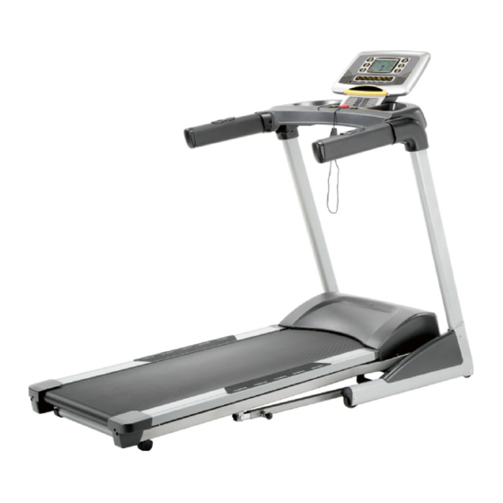
INTRODUCTION The treadmill has been designed and constructed to provide trouble free usage and enjoyable exercise. You can greatly improve your understanding and benefits of exercising by carefully reading the instructions given in this manual. Please familiarize yourself with the maintenance advice provided for you. SPECIFICATIONS •... -
Page 5: Assembly Pack Check List
ASSEMBLY PACK ASSEMBLY PACK CHECK LIST CHECK LIST #74. 3.5 × 12 m/m #99. 5/16" × 1/2" Sheet Metal Screw (4pcs) Button Head Socket Bolt (14pcs) #100. 5/16" × 18 × 1.5T #101. 5/16" × 23 × 1.5T Flat Washer (6pcs) Curved Washer (8pcs) #126. - Page 6 ASSEMBLY DRAWING Step1. Take out the Treadmill frome the carton and lay it aside on the smooth ground. Step 2. Connect the Computer Cable (Lower)(53) with the Right Upright (4). Step 3. Insert the Uprights (L, R)(5,4) into the Frame Base (2) with the 8pcs of 5/16" ×1/2" Button Head Socket Bolts (99), 4pcs of 5/16"...
-
Page 7: Assembly Drawing
ASSEMBLY DRAWING Step 4. Connecting the Computer Cable (Middle) (55) with the Computer Cable (Lower)(53). Step 5. Install the Console Support (6) into the Uprights (L,R) (5,4) with the 6pcs of 5/16" ×1/2" Button Head Socket Bolts (99) , 2pcs of 5/16" x 18 x 1.5T Flat Washers (100) and 4pcs of 5/16"... - Page 8 ASSEMBLY DRAWING Step 6. Install the Outer Handlebar Covers (L & R) (129 & 130) on the Console Support (6) with the 4pcs of 3.5 × 12 m/m Sheet Metal Screws (74) by using the Combination M5 Allen Wrench & Phillips Head Screw Driver (102) and tighten them.
- Page 9 ASSEMBLY DRAWING Step 7. Connecting the Computer Cable (Middle) (55) with the 10P Computer Cable (21-13). Connecting the Computer Cable (90-7) with the 11P Computer Cable (21-12). If there is HR receiver, connect 5-Pin HR receiver upper cable (21-14) and 5-Pin HR receiver upper cable (90-8).
-
Page 10: Keys For Meter Panel
FUNCTIONS COMPUTER OPERATION INSTRUCTIONS Keys for Meter Panel “Start” key Press this key, machine begins to run at the speed of 1.0km/h. When the machine runs at the speed of more than 3.5km/h. “Stop” key Press this key, machine stops slowly, during this operation, none keys are in function. If the speed is less than 3.5km/h, machine stops immediately. -
Page 11: Getting Started
FUNCTIONS “Speed” key ↑ ↓ " " " " Press this key Speed , it can adjust the running speed of the treadmill. “Incline” key ↑ ↓ " " " " Press this key Inclive , it can adjust the incline of the treadmill. “Speed shortcut key”... -
Page 12: Incline Feature
FUNCTIONS Incline Feature · Incline may be adjusted anytime after belt movement. · The incline range is from 0 to 12 levels. · ↑ ↓ " " " " Press the to achieve desired level of effort. Three Quick access key of 3, 6 and 9 are also available to adjust the incline percent. -
Page 13: Hrc Program
FUNCTIONS HRC Program: A. Choose HRC program and then press START to begin workout. All parameters will be counted with preset values. B. Use FAST/SLOW keys to set your age and then press ENTER. C. Use FAST/SLOW keys to set Target Heart Rate value then press ENTER D. - Page 14 FUNCTIONS...
- Page 15 UNFOLDING FOLDING TRANSPORT UNFOLDING Pull locking knob and hold running deck and lower down to the floor. (As shown Figure 1_2.) FOLDING Pull the locking knob with right hand, left hand lift the running deck up to 30cm then two hands lift it until it is locked by the locking knob.
-
Page 16: Belt Tracking Adjustmeant
BELT TRACKING ADJUSTMEANT If during use you notice that walking belt either shifts to the right or the left of center, first remove "Safety Key" and unplug equipment from AC power source. Using M6 Allen wrench provided, turn left rear roller adjustment as indicated below clockwise no more the 1/4" of a turn. -
Page 17: Treadmill Lubrication
TREADMILL LUBRICATION Your treadmill should require little maintenance other then periodically applying lubricant. Lubricating under the treadbelt will ensure superior performance and extend its life expectancy. HOW TO CHECK TREADBELT FOR PROPER LUBRICATION? Lift one side of the treadbelt and feel the top surface of the treadboard. If the surface is slick to the touch, then no further lubrication is required. -
Page 18: Weight Training
AEROBIC EXERCISE Aerobic exercise is any sustained activity that sends oxygen to your muscles via your heart and lungs. Aerobic exercise improves the fitness of your lungs and heart - your body’s most important muscle. Aerobic exercise fitness is promoted by any activity that uses your large muscle -arms, legs, or buttock, for example. -
Page 19: Inner Thigh Stretch
WARM UP Quadriceps Stretch With one hand against a wall for balance, reach behind you and pull your right foot up. Bring your heel as close to your buttocks as possible. Hold for 15 counts and repeat with left foot up. Inner Thigh Stretch Sit with the soles of your feet together with your knees pointing outward. - Page 20 OVERVIEW CHART...
-
Page 21: Parts List
PARTS DESCRIPTION Q'TY LIST Main Frame Frame Base Incline Bracket Right Upright Left Upright Console Support Outer Slide Inner Slide Locking Knob Incline Motor Drive Belt Motor Bracket Motor Running Belt Running Deck Front Roller W/Pulley 16~3 Magnet Rear Roller Sleeve for Frame Base Front Wheel Rear Wheel Sleeve Console Assembly... - Page 22 PARTS DESCRIPTION Q'TY LIST □25.4 × 25.4m/m_Square End Cap □20 × 40m/m_Square End Cap 800m/m_Safety Key Power Socket 1000m/m_Sensor W/Cable Sensor Rack Power Cord 100m/m_ Connecting Wire (White) 100m/m_Connecting Wire (Black) 100m/m_Connecting Wire (Black) Controller 1900m/m_Computer Cable (Lower) 700m/m_Computer Cable (Middle) Motor Bottom Cover 1/2"...
- Page 23 PARTS DESCRIPTION Q'TY LIST M8 × 1" × 1/4"_Flat Head Countersink Bolt 3/8" × 3"_Hex Head Bolt 5/16" × 1/2"_Button Head Socket Bolt 5/16" × 18 × 1.5T_Flat Washer 5/16" × 23 × 1.5T_ Combination M5 Allen Wrench & Phillips Head Screw Driver M6 (66 ×...