Casio SE-G1 Manual
Hide thumbs
Also See for SE-G1:
- User manual (76 pages) ,
- Quick start manual (2 pages) ,
- Quick programming manual (2 pages)
Advertisement
Table of Contents
Advertisement
Chapters
Table of Contents

Related Manuals for Casio SE-G1


Summary of Contents for Casio SE-G1
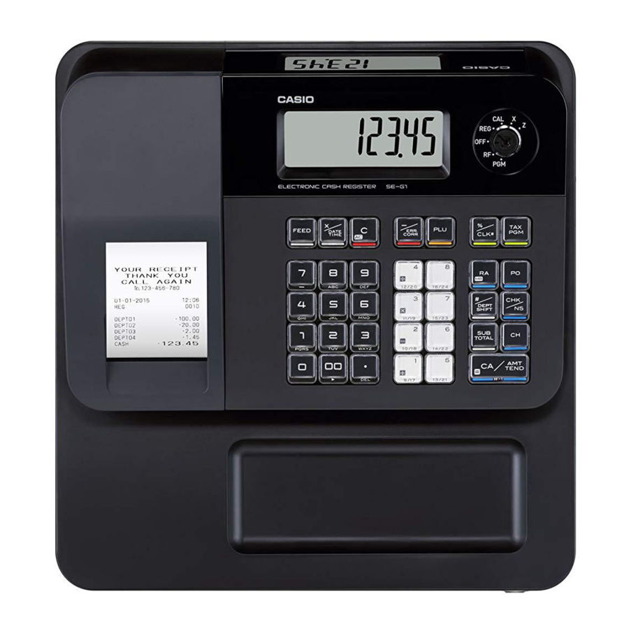
- Page 1 SERVICE MANUAL ELECTRONIC CASH REGISTER SE-G1/PCR-T273/SM-T274 (EX-256) JAN. 2013 Ver.1 : Jun. 2013...
-
Page 2: Table Of Contents
SE-G1/PCR-T273/SM-T274 CONTENTS 1. SPECIFICATIONS ......................1 2. INITIALIZATION ......................2 3. DISASSEMBLY ....................... 3 4. DIAGNOSTIC OPERATION ..................16 5. PCB LAYOUT ....................... 25 6. PARTS LIST ........................27 CAUTION RISK OF EXPLOSION IF BATTERY IS REPLACED BY AN INCORRECT TYPE. -
Page 3: Specifications
SE-G1/PCR-T273/SM-T274 1. SPECIFICATIONS 1-1. Electrical Specifications Power Consumption 100 V 120 V 220 V 230 V 240 V In operation Max. 122 mA 111 mA 79 mA 75 mA 74 mA Mode off Max. 12.4 mA 11.4 mA 12 mA 12.4 mA... -
Page 4: Initialization
SE-G1/PCR-T273/SM-T274 2. INITIALIZATION (1) Remove the memory protection batteries. Memory protection batteries (2) If the Power cord is plugged to a power outlet, unplug it. (3) Wait for 15 seconds, and set the memory protection batteries again. (4) Set the paper. -
Page 5: Disassembly
SE-G1/PCR-T273/SM-T274 3. DISASSEMBLY 3-1. Important • Please note that the product on this manual may appear to be different from the actual one according to the changes such as engineering design change. • Be sure to unplug the power cord and remove the roll paper before starting any repair/ maintenance. - Page 6 SE-G1/PCR-T273/SM-T274 3-2. Flowchart See the flowchart below for the order of disassembling major components. A. COVER/PRINTER, REEL (PULLY/WIND, SPOOL/PAPER), Paper roll, COVER/BATTERY, Memory protection batteries S Type M Type Drawer Type? B. MAIN-UNIT S-type C. MAIN-UNIT M-type E. ASSY/MOTOR, D. AC-ADAPTOR G. PCB ASSY/E256-1 ASSY/MODE KEY F. DISPLAY UNIT H. MOUNT/PCB I.
- Page 7 SE-G1/PCR-T273/SM-T274 B. MAIN-UNIT S-type B-1. Remove the cable tie. B-2. Pull the drawer release lever and then remove the drawer. NOTE: In case the drawer is locked with a drawer lock key, the lever does not activate. Drawer release lever...
- Page 8 SE-G1/PCR-T273/SM-T274 B-5. Disconnect the DRAWER connector. Connector NOTES ON ASSEMBLY Hook the DRAWER cable on the hook. DRAWER UNIT B-6. Undo three screws and remove the COVER/PCB. Screws (S2) MAIN UNIT COVER/PCB – 6 –...
- Page 9 SE-G1/PCR-T273/SM-T274 C. MAIN-UNIT M-type C-1. Remove the cable tie. C-2. Pull the drawer release lever and then remove the drawer. NOTE: In case the drawer is locked with a drawer lock key, the lever does not activate. Cable tie Drawer release lever NOTES ON ASSEMBLY • Be sure to attach the cable tie.
- Page 10 SE-G1/PCR-T273/SM-T274 C-5. Loosen the nut and disconnect the ground wire. C-6. Disconnect the DRAWER connector. C-7. Remove the COVER/PCB. COVER/PCB Ground wire Connector C-8. Place the DRAWER back in the MAIN UNIT. C-9. Undo one screw. C-10. Slide the MAIN UNIT toward the back to remove it.
- Page 11 SE-G1/PCR-T273/SM-T274 D. AC-ADAPTOR D-1. Undo two screws. (M-type only) Screws (S3) D-2. Disconnect one connector. D-3. Remove the PS-ASSY. PS-ASSY NOTES ON ASSEMBLY Run the cable under the motor. Connector PS-ASSY PS-UNIT HOLDER/PS-CORD CORD/POWER HOLDER/BUSH – 9 –...
- Page 12 SE-G1/PCR-T273/SM-T274 NOTES ON ASSEMBLY When the AC-ADAPTOR is replaced with a new part, attach the cable tie and tape. Cable tie Tape E. ASSY/MOTOR, ASSY/MODE KEY ASSY/MOTOR E-1. Disconnect one connector. E-2. Undo two screws and then remove the ASSY/MOTOR. ASSY/MODE KEY E-3. Disconnect one FFC. E-4. Undo one screw and then remove the ASSY/MODE KEY.
- Page 13 SE-G1/PCR-T273/SM-T274 F. DISPLAY UNIT F-1. Undo four screws. F-2. Peel off the tape and then disengage the FFC. Screws (S7) Tape F-3. Remove the DISPLAY UNIT. DISPLAY UNIT NOTES ON ASSEMBLY Be sure that the LCD surfaces are clean. – 11 –...
- Page 14 SE-G1/PCR-T273/SM-T274 F-4. Disengage two hooks and then remove the FRAME/DISPLAY. Hooks FRAME/DISPLAY – 12 –...
- Page 15 SE-G1/PCR-T273/SM-T274 G. PCB ASSY/E256-1 G-1. Disconnect one connector and two FFC. G-2. Undo two screws. Connector Screws (S4) G-3. Remove the E277-1-ASSY. Unhook the PCB. PCB ASSY/E256-1 – 13 –...
- Page 16 SE-G1/PCR-T273/SM-T274 H. MOUNT/PCB H-1. Undo three screws. H-2. Remove the MOUNT/PCB. Screws (S4) MOUNT/PCB Screw (S3) I. KEY-BOARD-ASSY I-1. Undo four screws. KEY-BOARD-ASSY Screws (S3) I-2. Undo two screws and then disassemble the KEY-BOARD-ASSY. SHEET/COMMON Screws (S8) SPACER CHASSIS/KEY BOARD CHASSIS/KEY BOARD Hooks – 14 –...
- Page 17 SE-G1/PCR-T273/SM-T274 J. PRINTER J-1. Undo one screw. J-2. Remove the PRINTER. Screw (S3) PRINTER NOTE: The PLATEN ARM must be open to remove the PRINTER. ARM/PLATEN NOTE: When replacing the PRINTER with a new part, remove the roller from the new PRINTER and replace it with the roller for the PLATEN ARM.
-
Page 18: Diagnostic Operation
SE-G1/PCR-T273/SM-T274 4. DIAGNOSTIC PROGRAM 4-1. Launching The Diagnostic Program NOTE: If a receipt has been issued in other modes, the Diagnostic Program will not launch. When this happens, exit and restart the Diagnostic Program. To exit the Diagnostic Program, see "4-2. Exiting the Diagnostic Program". - Page 19 SE-G1/PCR-T273/SM-T274 4-3. Notes For The Diagnostic Program • To forcibly terminate a test, press y key or turn the Mode Switch to [OFF]. If a test is terminated, the device prints out the following: • For the number of test to perform, you may select "once" or "infinite loop".
- Page 20 SE-G1/PCR-T273/SM-T274 4-5. Operation Of Each Test Status Display [Function] The device status is indicated with ON/OFF of the segment. [Display] The figure below shows the relative display positions for the status information. 1 Mode Switch...
- Page 21 SE-G1/PCR-T273/SM-T274 Batch Test [Function] Display, ROM, printer, time setting, drawer and buzzer tests are performed continuously. [Operation] Command : 1 k Performs the following tests in sequence. NOTE: Refer to each check item for details. (1) Display test NOTE: Press any key to go to the next test.
- Page 22 SE-G1/PCR-T273/SM-T274 Internal ROM Check SUM Test [Function] Performs the ROM check sum test. [Operation] Command : n 5 1 8 k n: Number of times to run Once (Can be omitted) 1 ~ 9 Infinite loop (To forcibly terminate the test, press the y key.)
- Page 23 SE-G1/PCR-T273/SM-T274 Internal Printer Character Print Test [Function] Tests if the internal printer prints characters correctly. [Operation] Command : a n 0 3 0 k a: Printing property Normal print out Reduced size print out c: Characters to be printed Prints the character “B”...
- Page 24 SE-G1/PCR-T273/SM-T274 Time Setting/Time Display [Function] Allows you to check or change the time (hour, minutes, seconds) and date (year, month, day) that are currently set. [Operation] <Time setting> Command : h s 0 0 7 0 k Hour Minutes Seconds •...
- Page 25 SE-G1/PCR-T273/SM-T274 Drawer Open Test [Function] Tests whether drawers operate correctly. The drawer sensor checks every two seconds while the drawer open test is performed infinite times. Only when the drawer is closed, the drawer is reopened. [Operation] Command : n 0 9 1 k...
- Page 26 SE-G1/PCR-T273/SM-T274 Key Test [Function] Tests if keys are recognized correctly. Each key is assigned with a hard key code. This test checks if correct hard key cords are assigned. All keys except for l and y key may be tested.
-
Page 27: Pcb Layout
SE-G1/PCR-T273/SM-T274 5. PCB LAYOUT 5-1. E256-1 PCB – 25 –... - Page 28 SE-G1/PCR-T273/SM-T274 5-2. E256-E2 PCB – 26 –...
-
Page 29: Parts List
3. The numbers in item column correspond to the same numbers in drawing. 4. CASIO does not supply the spare parts without parts code. 5. Refer to the latest "Parts Price Code" at “PARTS FINDER” on the Casio Service WEB site (https://www.servicecasio.com). -
Page 30: Explode View
SE-G1/PCR-T273/SM-T274 6-1. EXPLODED VIEW FINAL-ASSY S-type M-type MAIN-UNIT MAIN-UNIT DL-1335 DL-1844 DL-1845 DL-2816 DL-2817 EU &UK only – 28 –... - Page 31 SE-G1/PCR-T273/SM-T274 MAIN-UNIT S-type M-type KEY-BOARD-ASSY DISPLAY PCB ASSY/E256-1 18-1 FUSE – 29 –...
-
Page 32: Parts List
SE-G1/PCR-T273/SM-T274 6-2. PARTS LIST 1 SE-G1SB 4 SE-G1SA 7 SE-G1MB 10 SE-G1MK 13 SE-G1SB-WE 16 SM-T274 2 SE-G1SD 5 SE-G1SK 8 SE-G1MG 11 PCR-T273 14 SE-G1SK-WE 17 SE-G1SD-WE 3 SE-G1SG 6 SE-G1T 9 SE-G1MA 12 SE-G1SC 15 SE-G1MB-WE Q'TY Item Code No. - Page 33 SE-G1/PCR-T273/SM-T274 1 SE-G1SB 4 SE-G1SA 7 SE-G1MB 10 SE-G1MK 13 SE-G1SB-WE 16 SM-T274 2 SE-G1SD 5 SE-G1SK 8 SE-G1MG 11 PCR-T273 14 SE-G1SK-WE 17 SE-G1SD-WE 3 SE-G1SG 6 SE-G1T 9 SE-G1MA 12 SE-G1SC 15 SE-G1MB-WE Q'TY Item Code No. Parts Name...
- Page 34 SE-G1/PCR-T273/SM-T274 1 SE-G1SB 4 SE-G1SA 7 SE-G1MB 10 SE-G1MK 13 SE-G1SB-WE 16 SM-T274 2 SE-G1SD 5 SE-G1SK 8 SE-G1MG 11 PCR-T273 14 SE-G1SK-WE 17 SE-G1SD-WE 3 SE-G1SG 6 SE-G1T 9 SE-G1MA 12 SE-G1SC 15 SE-G1MB-WE Q'TY Item Code No. Parts Name...
-
Page 35: Drawer S-Type (Dl-1335/1844/1845)
SE-G1/PCR-T273/SM-T274 6-3. DRAWER S-type (DL-1335/1844/1845) EXPLODED VIEW DL-1844/1845 DL-1335 – 33 –... - Page 36 SE-G1/PCR-T273/SM-T274 PARTS LIST DL-1335 DL-1844 DL-1845 Q'TY Item Code No. Parts Name Specification 10449184 CASE/MAIN/BK RJE504018-001V01 10449188 CASE/MAIN/WE RJE504018-002V01 10449185 LEVER/HOOK RJE504008-001V01 10384548 ROLLER/PLASTIC PB-19B2 10201068 LOCK/SPRING RJE500007-001V02 10194207 SPRING/PRESS E412137-001V02 10167366 RUBBER/PAD RJE501204-001V01 10080189 SUB ASSY/SOLENOID E341255*2 10260417 AXIS/LEVER HOOK...
-
Page 37: Drawer M-Type (Dl-2816/2817)
SE-G1/PCR-T273/SM-T274 6-4. DRAWER M-type (DL-2816/2817) EXPLODED VIEW S1 S2 – 35 –... - Page 38 SE-G1/PCR-T273/SM-T274 PARTS LIST DL-2816 DL-2817 Q'TY Item Code No. Parts Name Specification 10445372 CASE/MAIN RJE502983-002V02 10447862 CASE/MAIN RJE502983-003V02 55000619 ROLLER/DELRIN DR-19B1 10236805 LEVER/HOOK E341286-001V03 10127603 AXIS/LEVER HOOK RJE500674-001V01 10201068 LOCK/SPRING RJE500007-001V02 62465010 SPRING/PRESS E412069-1 10078759 E240841-1 RAIL/MLED18 10078760 E240842-1 RAIL/MRED18...
- Page 39 Ver.1 : Jun. 2013 • Correction of the EXPLODED VIEW (P33) • Correction of the PARTS LIST (P34) CASIO COMPUTER CO., LTD. CS Technical Department TOKYO, JAPAN...