Table of Contents
Advertisement
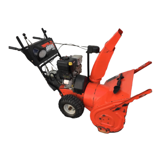
Sno-Thro
Owner/Operator Manual
Models
926001 – ST926LE
926002 – ST11528LE
926003 – ST1332LE
926004 – ST926DLE
926005 – ST11526DLE
926006 – ST1328DLE
926101 – ST926LE
926102 – ST11528LE
926103 – ST1332LE
926300 – ST11526DLE
926301 – ST926DLE
926302 – ST1332LE
926303 – ST1328LE
926304 – ST11528LE
926500 – ST1332DLE
926501 – ST1336DLE
926504 – ST8526LE
926505 – ST8526L
ENGLISH
FRANÇAIS
DEUTSCH
ITALIANO
SUOMI
ESPAGÑOL
NORSK
SVENSKA
РУССКИЙ ЯЗЫК
POLSKI
TÜRKÇE
ČESKY
®
Transfer
Coller l'autocollant du
model &
modèle et du numéro de
serial number
série dans cet encadré.
label from
Transferir aquí la etiqueta
product
del modelo y número de
registration
serie del registro del
here.
producto.
00483700 12/05
Printed in USA
Advertisement
Table of Contents

Related Manuals for Ariens 926001-ST926LE


Summary of Contents for Ariens 926001-ST926LE
- Page 1 Sno-Thro Owner/Operator Manual Models 926001 – ST926LE 926002 – ST11528LE 926003 – ST1332LE 926004 – ST926DLE 926005 – ST11526DLE 926006 – ST1328DLE 926101 – ST926LE 926102 – ST11528LE 926103 – ST1332LE 926300 – ST11526DLE 926301 – ST926DLE 926302 – ST1332LE 926303 –...
- Page 2 Facsimile (920) 756-2407 We the undersigned, ARIENS COMPANY, certify that: Nous, soussignés ARIENS COMPANY, certifions que : Der Unterzeichnete, ARIENS COMPANY, bescheinigt, dass: La sottoscritta società ARIENS COMPANY certifica che: Nosotros, los abajo firmantes, ARIENS COMPANY, certificamos que: Undertegnede, ARIENS COMPANY, bekrefter at: Undertecknad, ARIENS COMPANY, intygar att: Allekirjoittanut, ARIENS COMPANY, vakuuttaa, että: My, niŸej podpisani, ARIENS...
- Page 3 – Pomiar wibracji (m/sec ) na rêkach operatora – Hodnota vibrací (m/s ) na rukou obsluhy Ariens Company Brillion, WI 54110-0157 USA Signature Signature Unterschrift Firma Firma Signatur Namnteckning Allekirjoitus Podpis Podpis 926300 926301 926302 926303 926304 926500 926501 926504 926505...
-
Page 4: Table Of Contents
WARRANTY......34 INTRODUCTION PRODUCT REGISTRATION The Ariens dealer must register the product at the time of purchase. Registering the product will help the company process warranty claims or contact you with the latest service information. -
Page 5: Safety
NOTE: To locate your nearest Ariens Dealer, go to www.ariens.com on the internet. WARNING: Improper assembly or adjustments can cause serious injury. 2. Understand all Safety Precautions provided in the manuals. WARNING: To avoid injury to hands and feet, always disengage clutches, shut off engine, and wait for all movement to stop before unclogging or working on snow thrower. - Page 6 Keep people away from unit while operating. Keep children out of work area and under watchful care of a responsible adult. OL4370 Never direct discharge towards persons or property that may be injured or damaged by thrown objects. OL0910 Stop engine, remove key, read manual before making any repairs or adjustments.
- Page 7 ALWAYS keep hands and feet away from all rotating parts during operation. Rotating parts can cut off body parts. NEVER place your hands or any part of your body or clothing inside or near any moving part while unit is running.
- Page 8 NEVER fill fuel tank when engine is running or hot from operation. NEVER fill or drain fuel tank indoors. Replace fuel cap securely and clean up spilled fuel. Never fill containers inside a vehicle or on a truck or trailer bed with a plastic liner. Always place containers on the ground away from your vehicle before filling.
-
Page 9: Assembly
WARNING: AVOID INJURY. Read and understand the entire Safety section before proceeding. WARNING: Dropping or tipping over boxed unit could result in personal injury or damage to unit. PACKAGE CONTENTS 1. Sno-Thro Unit 4. Literature Pack with Extra Shear Bolts 2. - Page 10 Install Discharge Chute and Discharge Chute Crank (Figure 5) 1. Grease underside of discharge chute ring (if not already greased). 2. Remove mounting hardware from auger housing. 3. Install discharge chute over opening in the auger housing. Finger tighten the mounting hardware removed in step 2.
- Page 11 Use the handlebar hardware locations on the side of the unit frame to determine which hole gets used to secure the chute rod to the control assembly. 1. Chute Control Assembly 2. Hair Pin 3. Chute Rod 4. Handlebar Mounting Hardware Figure 7 6.
- Page 12 Connect Battery (926500, 501) 1. Remove wing nuts from battery cover. 2. Install wire lead to battery terminal. 3. Install battery cover and tighten wing nuts. Check Function of Dual Handle Interlock Without the engine running, press down (engage) both clutch levers.
-
Page 13: Controls And Features
Figure 10 CONTROLS AND FEATURES 1. Attachment Clutch Lever 2. Speed Selector 3. Deflector Remote Control 4. Chute Control 5. Traction Drive Clutch Lever 6. Oil Fill/Dipstick 7. Muffler Guard 8. Discharge Chute Deflector 9. Discharge Chute 10. Impeller 11. Clean-Out Tool 12. -
Page 14: Operation
WARNING: AVOID INJURY. Read and understand the entire Safety section before proceeding. WARNING: To avoid injury to hands and feet, always disengage clutches, shut off engine, and wait for all movement to stop before unclogging or working on snow thrower. Keep hands and feet away from auger and impeller. - Page 15 Throttle The throttle controls the engine speed. To increase or decrease the engine speed, adjust to: 1. Fast (normal or warm starts) 2. Part-Throttle 3. Slow (cold weather starts) 4. Stop (engine is off) (Not on 12V models) OL2720 Electric Starter (120V electric start models) The electric starter will start a properly choked and cranked engine when the key is turned (12V) or starter button (120V or 240V) is pushed.
-
Page 16: Filling Fuel Tank
If remote wheel lock does not lock or unlock properly, adjust or repair before operation (see REMOTE WHEEL LOCK (926002, 003, 102, 103, 302, 303, 304) on page 23). Axle Lock Pin (Figure 13) (926001, 101, 504, 505) Use the axle lock pin to lock or unlock the right or left wheel. - Page 17 IMPORTANT: DO NOT use gasohol or gasoline containing alcohol. See Engine Manual for correct type and grade of fuel. 5. Fill fuel tank to within 1/2 in. (1.2 cm) below bottom of filler neck with unleaded gasoline. NOTE: Tank capacity is 1 gallon (3.8 liters). 6.
-
Page 18: Snow Removal
NOTE: A warm engine requires less choking than a cold engine. 5. Set throttle to proper starting position. 6. Insert key into ignition switch. 12V - Turn key to RUN position. 120V or 240V - Push key into RUN position. DO NOT twist key after it is inserted. -
Page 19: Maintenance
ALWAYS direct snow away from area to be cleared and with direction of the wind. Ariens Dealers will provide any service or adjustments which may be required to keep your unit operating at peak efficiency. Should engine service be required, contact an Ariens dealer or an authorized engine manufacturer's service center. -
Page 20: Maintenance Schedule
2. Add lubricant if required. Allow oil to drain to level of plug and replace plug. IMPORTANT: Use only Ariens special gear lubricant L-2 (Part Number 00008000). Gearcase filler plug may require an application of Loc-Tite® 565 thread sealant with repeated servicing. - Page 21 GENERAL LUBRICATION IMPORTANT: Wipe each fitting clean before and after lubrication. Do not wipe gearcase filler plug; wiping the gearcase filler plug may remove thread sealant and cause leaks. IMPORTANT: DO NOT allow grease or oil to get on friction disc, friction plate or belts. NOTE: Apply Stens Mix Hi-Temp Grease or equivalent to the lubrication fittings.
-
Page 22: Service And Adjustments
3. Reposition scraper blade flush with runners and tighten lock nuts. SHEAR BOLTS IMPORTANT: Use only Ariens shear bolts for replacement. Use of any other type of shear bolt may result in severe damage to unit. Occasionally a foreign object may enter the... -
Page 23: Remote Wheel Lock
1. Upper Position 4. Upper Mounting Bolt 2. Lower Position 5. Lower Mounting Bolt 3. Handlebar Figure 21 NOTE: Insert the hair pin with the loop end on the left side of the chute rod so the control lever will cover its full range of travel. -
Page 24: Discharge Chute
5. Loosen the top jam nut 1 – 3 turns. 6. Tighten the bottom jam nut. 7. Re-install bottom cover. 8. Check function of remote wheel lock. If wheel lock does not function properly, take unit to Dealer for repairs. Finger tighten top jam nut, then loosen top jam nut 1 –... -
Page 25: Attachment Clutch/Brake Adjustment
If chute does not rotate freely: Tighten the cable by loosening the upper adjustment nut, and then tightening the lower adjustment nut against the bracket (Figure 27). Figure 27 SPEED SELECTOR ADJUSTMENT To adjust (Figure 28): 1. Place unit into service position. 2. -
Page 26: Traction Drive Clutch Adjustment
1. Engine Sheave 5. Attachment Pulley 2. Attachment Drive Belt 6. Attachment Idler Adjustment Nut 3. Belt Finger 4. Attachment Belt Idler Figure 30 3. Check brake. When the clutch lever is disengaged, the brake must contact attachment belt. When the clutch lever is engaged, the brake must be more than 1/16 in. - Page 27 5. Adjust spring extension. a.With the traction drive clutch lever disengaged, loosen the jam nut on the cable adjuster. b.Turn the adjuster body up the cable for more spring extension. c.Turn the adjuster body down the cable for less spring extension. d.Finger tighten the jam nut, and then hold the adjuster body with pliers and tighten the jam nut with wrench.
- Page 28 Install new attachment drive belt: 1. Place new attachment belt onto attachment pulley. NOTE: Holding down the attachment clutch lever will make it easier to reconnect the housing and frame. 2. Tip housing and frame back together and secure with hex bolts. 3.
-
Page 29: Storage
Traction Belt (926003, 006, 103, 302, 303, 500, 501) 00170800 Friction Disc 51001500 Shear Bolt Kit ACCESSORIES See your authorized Ariens dealer to add the additional accessories available to your Sno-Thro. Part No. Description 72403600 120 Volt Starter Kit 72402200... -
Page 30: Troubleshooting
PROBLEM PROBABLE CAUSE 1. Fuel tank is empty. Engine will not crank/start. 2. Fuel shut-off valve closed. 3. Build up of dirt and residue around governor/carburetor. 4. Key Switch not in run position. 5. Ignition switch starter circuit not functioning. 6. -
Page 31: Specifications
Model Number 926001 Description ST926LE Engine - Tecumseh LH318SA Power Max - HP (kW) 9.0 (6.7) Fast Idle Speed - RPM (min Displacement - in. (cc) 19.4 (318) Electric Start 120V Fuel Tank Capacity - qt (Liters) 4 (3.8) Snow Clearing Width - in. - Page 32 Model Number 926101 Description 926LE Engine - Tecumseh LH318SA Power Max - HP (kW) 9.0 (6.7) Fast Idle Speed - RPM (min Displacement - in. (cc) 19.4 (318) Electric Start 120V Fuel Tank Capacity - qt (Liters) 4 (3.8) Snow Clearing Width - in.
- Page 33 Model Number 926303 Description ST1328LE Engine - Tecumseh OH358SA Power Max - HP 13.0 (9.7) (kW) Fast Idle Speed - RPM (min Displacement - in. (cc) 21.8 (358) Electric Start 240V Fuel Tank Capacity - qt (Liters) 4 (3.8) Snow Clearing Width - in.
-
Page 34: Warranty
1000 hours of use, whichever comes first, if any product is rented or leased. Ariens Company • 655 W. Ryan St, P.O. Box 157 • Brillion, WI 54110-0157• (920) 756-2141 • www.ariens.com ALW2 - 121305 Warranties... - Page 35 (12) months after the date of purchase. Ariens may from time to time change the design of its products. Nothing contained in this warranty shall be construed as obligating Ariens to incorporate such design changes into previously manufactured products, nor shall such changes be construed as an admission that previous designs were defective.
- Page 36 Ariens Company 655 West Ryan Street P.O. Box 157 Brillion, WI 54110-0157 920-756-2141 Fax 920-756-2407 www.ariens.com...