Hisense AUD-18UX4SGKL Service Manual
Dc inverter air conditioner
Hide thumbs
Also See for AUD-18UX4SGKL:
- User and installation instructions manual (49 pages) ,
- Service manual (77 pages) ,
- Technical & service manual (136 pages)
Table of Contents
Advertisement
Quick Links
DC INVERTER AIR CONDITIONER
SERVICE MANUAL
UNIT:
AUD-18UX4SGKL
AUD-24UX4SZLH
AUD-36UX4SAMH
AUD-48UX6SPHH
AUD-60UX6SPHH
AUD-18UX4SZKL1
AUD-24UX4SALH1
AUD-36UX4SAMH1
AUV-18UR4SZA1
AUV-24UR4SAA1
AUV-36UR4SAB1
AUV-48UR6SPC
AUV-60UR6SPC
Hisense Corporation
AUC-18UX4SGAA
AUC-24UX4SZEA
AUC-36UX4SAEA
AUC-48UX6SPFA
AUC-60UX6SPFA
AUC-18UR4SZAA1
AUC-24UR4SAEA1
AUC-36UR4SAEA1
V:3.0
Advertisement
Table of Contents

Related Manuals for Hisense AUD-18UX4SGKL


Summary of Contents for Hisense AUD-18UX4SGKL
-
Page 1: Service Manual
DC INVERTER AIR CONDITIONER SERVICE MANUAL V:3.0 UNIT: AUD-18UX4SGKL AUC-18UX4SGAA AUD-24UX4SZLH AUC-24UX4SZEA AUD-36UX4SAMH AUC-36UX4SAEA AUD-48UX6SPHH AUC-48UX6SPFA AUD-60UX6SPHH AUC-60UX6SPFA AUD-18UX4SZKL1 AUC-18UR4SZAA1 AUD-24UX4SALH1 AUC-24UR4SAEA1 AUD-36UX4SAMH1 AUC-36UR4SAEA1 AUV-18UR4SZA1 AUV-24UR4SAA1 AUV-36UR4SAB1 AUV-48UR6SPC AUV-60UR6SPC Hisense Corporation... -
Page 2: Table Of Contents
Table of Contents Page 1.GENERAL 2.SPECIFICATION 3.OUTLINES AND DIMENSIONS 3-1 INDOOR 3-2 OUTDOOR 4. DIAGRAM&DATA 4-1 Refrigerant Flow Diagram 4-2MAX. Refrigerant Pipe Length and Height Difference 4-3 Electric Diagrams 4-4Air flow and ESP Chart Diagrams(for duct type) 5.ELECTRICAL DATA 5-1 Electric Wiring Diagrams 5-2. - Page 3 1.GE ENERAL Features t Type Ai ir Conditi oner eatures Save Inst tallation Spa indoor unit c can be install led inside the e ceiling con nveniently. Optional Static Press 8k: optional 1 10Pa /30Pa, 24K/36K 50 Pa/80Pa(Fo r AUD-24UX4 4SALH1&AUD D-36UX4SAMH H1,freely...
-
Page 4: General
1.GENERAL The unit is also installed with down-air-inlet type and the noise will increase about 5-6 Self Recovery of Power Break When the power supply is recovered after break, all preset are still effective and the air-conditioner can run according to the original setting. Fault Self-diagnose Function When there is something wrong with the air-conditioner,the micro computer could diagnose the faults, which can be read from the display and is convenient for... - Page 5 1.GE ENERAL Cassette T Type Air Condition eatures Save Inst tallation Spa The indoo or unit can b be installed in nside the ceil ling convenie ently. High Effic ciency and E Environment Friendly New w Refrigeran t-R410A R410A ca an protect th e environme ent and do no...
- Page 6 1.GENERAL Ceiling &Floor Air Conditioner Features Save Installation Space The indoor unit’s thickness is only 230mm,can be installed inside the ceiling conveniently. Flexible Installation Options According to the actual installation space,The indoor unit can be installed in the ceiling or on the floor. One unit, Two installation method. High Efficiency and Environment Friendly New Refrigerant-R410A R410A can protect the environment and do not harm to the ozone layer.
- Page 7 1.GENERAL Fault Self-diagnose Function When there is something wrong with the air-conditioner, the micro computer could diagnose the faults, which can be read from the display and is convenient for maintenance. 5 ...
-
Page 8: Product Lineup
1.GENERAL Product Lineup Type Model Duct Type AUD- ● ● ● ● ● Cassette Type AUC- ● ● ● ● ● Ceiling&Floor AUV- ● ● ● ● ● type 6 ... -
Page 9: Model Identification
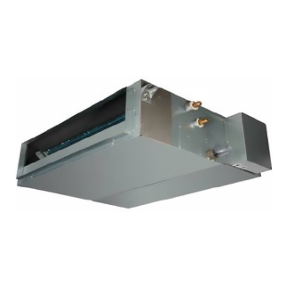
1.GENERAL 1.3 MODEL IDENTIFICATION A U C -18 U R 4 S Z A A 1 serial number K:Outdoor Unit Indetification G:Indoor Unit Indetification S:Refrigement R410A F:Refrigement R22 4:220V-240V/50HZ/1P 6:380V-415V/50HZ/3P X: Wire Romote Controller R:Wireless Romote Controller U:DC-Invert Heat Pump Type H:Heat Pump Type C:Cooling Only Cool Capacity:18x10 Btu/h Type:D-Duct Type,C-Cassette Type,V-Ceiling&Floor Type,W-Outdoor Unit Unit... - Page 10 1.GE ENERAL .4 Produ uct Pict ture uct Typ Model AUD-18UX4 4SGKL AUD-24UX4S SZLH ndoor utdoor AUD-48UX6S SPHH Model AUD-36UX4 4SAMH AUD-48UX6S SPHH ndoor utdoor 8 ...
- Page 11 1.GE ENERAL AUD-18UX4 4SZKL1 AUD-24UX4S SALH1 Model ndoor utdoor AUD-36UX4 4SAMH1 Model ndoor utdoor 9 ...
- Page 12 1.GE ENERAL assette T Model AUC-18UX4 4SGAA AUC-24UX4S SZEA ndoor utdoor AUC-48UX6S SPFA Model AUC-36UX4 4SAEA AUC-60UX6S SPFA ndoor utdoor ...
- Page 13 1.GE ENERAL AUC-24UR4S SAEA1 AUC-18UR4 4SZAA1 Model AUC-36UR4S SAEA1 ndoor utdoor ...
- Page 14 1.GENERAL Ceiling &Floor Type Model AUV-18UR4SZA1 AUV-24UR4SAA1 Indoor Outdoo AUV-48UR6SPC Model AUV-36UR4SAB1 AUV-60UR6SPC Indoor Outdoo 12 ...
-
Page 15: Display Panel
1.GENERAL DISPLAY PANEL: Cassette Type 18k 24K,36K,48K,60K 13 ... - Page 16 1.GENERAL Ceiling&Floor type 14 ...
- Page 17 2.SPECIFICATIONS 2. Specifications Duct Type Model AUD-18UX4SZKL1 AUD-24UX4SALH1 AUD-36UX4SAMH1 AUD-18UX4SGKL AUD-24UX4SZLH AUD-36UX4SAMH AUD-48UX6SPHH AUD-60UX6SPHH Indoor model AUD-18UX4SKL1 AUD-24UX4SLH1 AUD-36UX4SMH1 AUD-18UX4SKL AUD-24UX4SLH AUD-36UX4SMH AUD-48UX4SHH AUD-60UX4SHH Outdoor model AUW-18U4SZ1 AUW-24U4SA1 AUW-36U4SA1 AUW-18U4SG AUW-24U4SZ AUW-36W4SA AUW-48U6SP AUW-60U6SP Ph-V-H Power supply 20V-240V ~/50Hz 380V-415V,3N~/50Hz 12.6 Cooling...
-
Page 18: Specification
2.SPECIFICATIONS Model AUD-18UX4SZKL1 AUD-24UX4SALH1 AUD-36UX4SAMH1 AUD-18UX4SGKL AUD-24UX4SZLH AUD-36UX4SAMH AUD-48UX6SPHH AUD-60UX6SPHH Indoor model AUD-18UX4SKL1 AUD-24UX4SLH1 AUD-36UX4SMH1 AUD-18UX4SKL AUD-24UX4SLH AUD-36UX4SMH AUD-48UX4SHH AUD-60UX4SHH Outdoor model AUW-18U4SZ1 AUW-24U4SA1 AUW-36U4SA1 AUW-18U4SG AUW-24U4SZ AUW-36W4SA AUW-48U6SP AUW-60U6SP 2433;U-W :2433; 2433;U-W :2433; V-W: 2.304(at V-W: 2.304(at 25℃) 25℃)... -
Page 19: Specifications
2.SPECIFICATIONS Model AUD-18UX4SZKL1 AUD-24UX4SALH1 AUD-36UX4SAMH1 AUD-18UX4SGKL AUD-24UX4SZLH AUD-36UX4SAMH AUD-48UX6SPHH AUD-60UX6SPHH Indoor model AUD-18UX4SKL1 AUD-24UX4SLH1 AUD-36UX4SMH1 AUD-18UX4SKL AUD-24UX4SLH AUD-36UX4SMH AUD-48UX4SHH AUD-60UX4SHH Outdoor model AUW-18U4SZ1 AUW-24U4SA1 AUW-36U4SA1 AUW-18U4SG AUW-24U4SZ AUW-36W4SA AUW-48U6SP AUW-60U6SP Outdoor Net/Gross 45/51 69/73 70/74 35.5/39 50/56 70/74 101/107 108/112... - Page 20 2.SPECIFICATIONS Cassette type AUC-36UX4SAEA AUC-48UX6SPFA AUC-60UX6SPFA Model AUC-18UR4SZAA1 AUC-24UR4SAEA1 AUC-36UR4SAEA1 AUC-18UX4SGAA AUC-24UX4SZEA AUC-36UX4SEA AUC-48UX4SFA AUC-60UX4SFA Indoor model AUC-18UR4SAA1 AUC-24UR4SEA1 AUC-36UR4SEA1 AUC-18UX4SAA AUC-24UX4SEA AUW-36W4SA AUW-48U6SP AUW-60U6SP Outdoor model AUW-18U4SZ1 AUW-24U4SA1 AUW-36U4SA1 AUW-18U4SG AUW-24U4SZ Power supply Ph-V-Hz 20V-240V ~/50Hz 380V-415V,3N~/50Hz 5(1.2-6.5) 7.0(2.2-8.0) 9.5(3.6~10.5) 32,400 Cooling 17,100(4,100-22...
- Page 21 2.SPECIFICATIONS AUC-36UX4SAEA AUC-48UX6SPFA AUC-60UX6SPFA Model AUC-18UR4SZAA1 AUC-24UR4SAEA1 AUC-36UR4SAEA1 AUC-18UX4SGAA AUC-24UX4SZEA AUC-36UX4SEA AUC-48UX4SFA AUC-60UX4SFA Indoor model AUC-18UR4SAA1 AUC-24UR4SEA1 AUC-36UR4SEA1 AUC-18UX4SAA AUC-24UX4SEA Outdoor model AUW-18U4SZ1 AUW-24U4SA1 AUW-36U4SA1 AUW-18U4SG AUW-24U4SZ AUW-36W4SA AUW-48U6SP AUW-60U6SP DA131S1B-28F DA230S2C-31M DA250S2C-30M DA130S1C-20F ATL165SD-C9A Model DA250S2C-30MT TNB306FPNMC LNB42FSAMC Type Rotary U-V: U-V:...
- Page 22 2.SPECIFICATIONS AUC-36UX4SAEA AUC-48UX6SPFA AUC-60UX6SPFA Model AUC-18UR4SZAA1 AUC-24UR4SAEA1 AUC-36UR4SAEA1 AUC-18UX4SGAA AUC-24UX4SZEA AUC-36UX4SEA AUC-48UX4SFA AUC-60UX4SFA Indoor model AUC-18UR4SAA1 AUC-24UR4SEA1 AUC-36UR4SEA1 AUC-18UX4SAA AUC-24UX4SEA Outdoor model AUW-18U4SZ1 AUW-24U4SA1 AUW-36U4SA1 AUW-18U4SG AUW-24U4SZ AUW-36W4SA AUW-48U6SP AUW-60U6SP Panel L×W×H 650×650×30 950×950×37 950×950×37 650×650×30 950×950×37 950×950×37 950×950×37 950×950×37 Indoor L×W×H 770×750×310...
- Page 23 2.SPECIFICATIONS Ceiling & Floor type Model AUV-18UR4SZA1 AUV-24UR4SAA1 AUV-36UR4SAB1 AUV-48UR6SPC AUV-60UR6SPC Power supply Ph-V-Hz 1N,220V-240V/50Hz 3N~,380V-415V/50Hz 12.6 17.0 Cooling Btu/h 17,000 23,900 31,400 43,000 58,000 Capacity 11.0 15.3 20.5 Heating Btu/h 19,800 29,000 37,500 52,200 70,000 Dehumidification Cooling 1.55 3.05 3.92 5.295 Rated input Heating 1.75 2.77...
- Page 24 2.SPECIFICATIONS Model AUV-18UR4SZA1 AUV-24UR4SAA1 AUV-36UR4SAB1 AUV-48UR6SPC AUV-60UR6SPC Winding M:79.7;A:59.4,20.2,10 resistance M:187A:245,60,33,143 M:209.4;A:245,60,33,143 M:75;A:97.5 M:79.7;A:59.4,20.2,108 (at20℃) YDK65-6-9024 YDK65-6-9024 Model ARW4401QH SIC-71FW-D8121-1 SIC-71FW-D8121-1 YDK65-6-9061 YDK65-6-9061 Outdoor Winding M:83;A1:23.4A2:14A1:6 M:83;A1:23.4A2:14A1: resistance M:231.5;A:168 M:78;A:36.2,51.5,109.2 M:59.1;A:85.8 63.5 (at20℃) type centrifugal fan Indoor Speed r.p.m 630/720/850 910/1030/1150 1080/1160/1220 1000/1100/1200...
- Page 25 2.SPECIFICATIONS Model AUV-18UR4SZA1 AUV-24UR4SAA1 AUV-36UR4SAB1 AUV-48UR6SPC AUV-60UR6SPC POWER) Gas/Liquid 12.7/6.35 15.88/9.52 15.88/9.52 19.05/9.52 19.05/9.52 Max. refrigerant pipe Refrigerant length piping Max. difference in level 20(outdoor blow:15) 20(outdoor blow:15) Connection method Flare Connection Power wiring 3 core x1.5 3 core x2.5 3 core x2.5 5 core x2.5 5 core x2.5...
-
Page 26: Outlines And Dimensions
3.OUTLINES AND DIMENSIONS 3-1 INDOOR Duct type... - Page 28 Cassette type 24K,36K...
- Page 29 48K,60K...
- Page 30 Ceiling&Floor Type...
-
Page 31: Outdoor
3-2.OUTDOOR 18K(AUW-18U4SG) - Page 32 18K(MODEL: AUW-18U4SZ1) 24K(MODEL: AUW-24U4SZ)
- Page 33 24&36K (MODEL: AUW-24U4SA1, AUW-36U4SA1, AUW-36W4SA)...
- Page 34 48K&60K (MODEL: AUW-48U6SP、AUW-60U6SP)...
-
Page 35: Piping Diagrams
4 DIAGRAM&DATA 4. Diagrams DATA & 4.1 Piping Diagrams 18k type 33 ... -
Page 36: Diagram&Data
4 DIAGRAM&DATA 24k &36K type Stop Valve Ambient temperature Ambient Discharge sensor temperature temperature sensor sensor 4-Way Valve Discharge Coil Pressure temperature Outdoor Switch sensor Coil heat temperature exchanger sensor Suction temperature sensor Indoor heat exchanger Defrost temperature sensor Accumulator Compressor strainer strainer... - Page 37 4 DIAGRAM&DATA 48K&60K Stop Valve Ambient temperature Ambient Discharge sensor temperature temperature Suction sensor sensor Pressure 4-Way Valve Switch Discharge Coil Pressure temperature Outdoor Switch sensor Coil heat temperature exchanger sensor Suction temperature sensor Indoor heat exchanger Defrost temperature sensor Accumulator Compressor strainer...
- Page 38 4 DIAGRAM&DATA 4-2MAX. Refrigerant pipe length and height difference *Do your best to reduce the pipe length. Long pipe may cause capacity of the indoor unit incline. Total refrigerant pipe length Outdoor unit precharged 0m~5m 5m~60m AUW‐18U4SG 1270g 0g Xg = 15g / m × (Total pipe length(m) ‐5) AUW‐24U4SZ 1500g 0g AUW-36U4SA 2100g 0g AUW-18U4SZ1 1400g 0g AUW-24U4SA1 1680g 0g AUW-36U4SA1 2100g 0g Xg =35g / m ...
- Page 39 4 DIAGRAM&DATA 4-3ELECTRIC Diagrams Recommend Wire Size Power Source Transmitting Cable Model POWER SUPPLY Cable Size Size (mm2) (mm2) 220-240V,50Hz 3×1.5 4×0.75 24K/36K 220-240V,50Hz 3×2.5 4×0.75 380~415V,3N~,50Hz 48K/60K 5×2.5 4×0.75 ● Use an ELB (Electric Leakage Breaker). If not used, it will cause an electric shock or a fire.
- Page 40 4 DIAGRAM&DATA (B) Check to ensure that the stop valves of the outdoor unit are fully opened and then start the system. ● Pay attention to the following items while the system is running. (A) Do not touch any of the parts by hand at the discharge gas side, since the compressor chamber and the pipes at the discharge side are heated higher than 90 .
- Page 41 4 DIAGRAM&DATA 4-4Air flow and ESP Chart Diagrams(for duct type) 18K 18K Curve for 10Pa ESP 1000 Air flow(m3/h) 18K Curve for 30Pa ESP 1000 1100 Air flow(m3/h) 39 ...
- Page 42 4 DIAGRAM&DATA 24K 24K Curve for 50Pa ESP 700 800 900 1000 1100 1200 1300 1400 Air flow(m3/h) 24K Curve for 80Pa ESP 600 700 800 900 1000 1100 1200 1300 1400 1500 Air flow(m3/h) 40 ...
- Page 43 4 DIAGRAM&DATA (AC MOTOR) 36K Curve for 50Pa ESP 900 1100 1300 1500 1700 1900 Air flow(m3/h) 36K Curve for 80Pa ESP 800 1000 1200 1400 1600 1800 2000 Air flow(m3/h) 41 ...
- Page 44 4 DIAGRAM&DATA 48K 48K Curve for 80Pa ESP 1500 1700 1900 2100 2300 2500 Air flow(m³/h) 48K Curve for120Pa ESP 1500 1700 1900 2100 2300 2500 Air flow(m³/h) 42 ...
- Page 45 4 DIAGRAM&DATA 60K 60K Curve for 80Pa ESP 1500 1700 1900 2100 2300 2500 Air flow(m³/h) 60K Curve for120Pa ESP 1500 1700 1900 2100 2300 2500 Air flow(m³/h) 43 ...
- Page 46 5-1.Electrical wiring diagrams INDOOR UNIT Duct type AUD-18UX4SKL,AUD-18UX4SKL1...
-
Page 47: Electrical Data
AUD-24UX4SLH,AUD-36UX4SMH... - Page 48 AUD-24U4SLH1,AUD-36U4SMH1...
- Page 49 AUD-48UX4SHH,AUD-60UX4SHH...
- Page 50 Cassette type 24K ,36K,48K,60K...
- Page 51 Ceiling&Floor type 18K,48K,60K 24K,36K...
- Page 52 OUTDOOR UNIT AUW-18U4SG...
- Page 53 AUW-18U4SZ1...
- Page 54 AUW-24U4SZ...
- Page 55 AUW-24U4SA1...
- Page 56 AUW-36U4SA...
- Page 57 AUW-36U4SA1...
- Page 58 AUW-48U6SP AUW-60U6SP...
-
Page 59: Electric Control
5-2. Electric control Board 1. Indoor control board Duct type 18K,48K,60K &AUD-24UX4SLH, AUD-36UX4SMH AUD-24UX4SLH1, AUD-36UX4SMH1... - Page 60 CASETTE Type 24K,36K,48K,60K...
- Page 61 Ceiling & Floor type 18k,48k,60k 24k,36k...
- Page 62 2.Control board for outdoor unit 1) OUTDOOR CONTROL BOARD AUW-18U4SG 1) CONTROL BOARD(AUW-18U4SG) CONTROL BOARD(AUW-24U4SZ)...
- Page 63 AC fan motor Heater N N OUT Earth AC N IN 4-way valve AC L IN Heater L Communication SI IPM-SI Communication N IPM power High pressure switch Liquid and Gas Sensor Electric expansion valve Outdoor/suction/coil Sensor Overload protection switch Discharge Sensor CONTROL BOARD(AUW-36U4SA)...
- Page 64 4-way valve Heater N 4-way valve N OUT Heater L AC N IN AC fan motor Earth AC L IN Electric expansion valve Communication SI IPM power IPM-SI Communication N AC L OUT Suction Sensor High pressure switch Outdoor Sensor Discharge Sensor Low pressure switch coil/defrost Sensor...
- Page 65 (AUW-18U4SZ1,AUW-24U4SA1、AUW-36U4SA1)...
- Page 66 Heater N 4-way valve N OUT Heater L AC N IN Earth AC L IN Electric expansion valve Communication SI IPM power IPM-SI Communication N AC L OUT Suction Sensor High pressure switch Outdoor Sensor Discharge Sensor Low pressure switch coil/defrost Sensor IPM Board IPM Board(AUW-18U4SG)...
- Page 67 To Electrolytic Capacitor + To PFC Inductor-2 AC L IN To PFC Inductor-1 To Electrolytic Capacitor - AC N IN IPM Power To Compressor W To Compressor V To Compressor U To Main Control To Electrolytic Board Capacitor + (AUW-24U4SZ / AUW-36U4SA) To PFC To PFC Inductor-1...
- Page 68 (AUW-48U6SP、AUW-60U6SP) AC IN-W Compressor AC IN-V Contacto Compressor AC IN-U Inductor Compressor AC IN Inductor L1 Contact IPM-SI...
-
Page 69: Dip Switch Setting Of Outdoor
5-3. DIP SWITCH SETTING OF OUTDOOR AUW-18U4SZ1,AUW-24U4SA1,AUW-36U4SA1,AUW-36W4SA 48K&60K... -
Page 70: Digital Display Switch Of Outdoor
5-4. Digital Display Switch of Outdoor Digital Display Switch Introduction It can be used to check outdoor running parameters. There are 3 buttons on the digital display board: 1)SWITH button:Indoor parameters and outdoor parameters can be select in turn by press it. P--outdoor unit,H--indoor unit;... - Page 71 rapidly lowers. Parameters can be checked as following table below. Parameter Descriptions code Protect Code or Error Code Target Frequency Driver Frequency Outdoor Electronic expansion valve Opening Outdoor Electronic expansion valve Target Opening Upper DC Motor Revolving Speed AC Input Voltage Current P.10 Modular Temperature...
-
Page 72: Static Pressure Setting(Only For Duct Type)
5-5. Static Pressure Setting(only for duct type) CHANGE OF STATIC PRESSURE The static pressure outside the indoor unit can be chosen . Models except AUD-24UX4SALH1 & AUD-36UX4SAMH1 : You can change the static pressure by changing the fan motor terminal which refer to following Fig.below: AUD-24UX4SALH1 &... -
Page 74: Ambient Temperature Revise(Indoor)
5-6.AMBIENT TEMPERATURE REVISE(INDOOR) when indoor unit highly mounted,because of hot air floatation,cold air sinks,so the ambient temperature sensed by indoor unit is higher than the actual.Then the ambient temperature need to be revised. It can be changed by using specific wire remote controller(YXE-C01U). Operation details, please refer to wire remote controller manuals . -
Page 75: Sensor Parameter
5-7. Sensor parameter 1. THE PARAMETER OF OUTDOOR COMPRESSOR DISCHARGE TEMPERATURE SENSOR: (R =187.25K±6.3%;R =3.77K±2.5K;B0/100=3979K±1%) T [ ℃ ] Rmin [ KΩ ] Rnom [ KΩ ] Rmax [ KΩ ] DR(MIN)% DR(MAX)% 7.47 908.2603 985.5274 1065.1210 -7.84 7.42 855.3955 927.6043 1001.9150 -7.78... - Page 76 T [ ℃ ] Rmin [ KΩ ] Rnom [ KΩ ] Rmax [ KΩ ] DR(MIN)% DR(MAX)% 5.50 107.8202 114.4973 121.1586 -5.83 5.46 102.8560 109.1728 115.4734 -5.79 5.41 98.1470 104.1246 110.0855 -5.74 5.37 93.6787 99.3367 104.9778 -5.70 5.33 89.4378 94.7946 100.1342 -5.65...
- Page 77 T [ ℃ ] Rmin [ KΩ ] Rnom [ KΩ ] Rmax [ KΩ ] DR(MIN)% DR(MAX)% 3.87 17.6458 18.3926 19.1338 -4.06 3.84 16.9986 17.7113 18.4185 -4.02 3.83 16.3784 17.0537 17.7335 -3.96 3.77 15.7839 16.4332 17.0774 -3.95 3.74 15.2139 15.8338 16.4488 -3.92...
- Page 78 T [ ℃ ] Rmin [ KΩ ] Rnom [ KΩ ] Rmax [ KΩ ] DR(MIN)% DR(MAX)% 2.55 4.1453 4.2568 4.3683 -2.62 2.52 4.0218 4.1287 4.2355 -2.59 2.50 3.9024 4.0049 4.1074 -2.56 2.47 3.7872 3.8854 3.9837 -2.53 2.44 3.6758 3.7700 3.8643 -2.50...
- Page 79 2. THE PARAMETER OF THE OTHER SENSOR IN INDOOR AND OUTDOOR UNIT: ( R =15K±2%; B0/100=3450K±2%) T [℃] Rmin [ KΩ ] Rnom [ KΩ ] Rmax [ KΩ ] DR(MIN)% DR(MAX)% 6.12 60.78 64.77 68.99 -6.16 5.83 57.75 61.36 65.16 -5.88 5.57...
- Page 80 T [℃] Rmin [ KΩ ] Rnom [ KΩ ] Rmax [ KΩ ] DR(MIN)% DR(MAX)% 2.33 9.199 9.422 9.647 -2.37 2.40 8.826 9.047 9.269 -2.44 2.48 8.470 8.689 8.910 -2.52 2.57 8.129 8.347 8.567 -2.61 2.66 7.804 8.021 8.240 -2.71 2.76 7.493...
- Page 81 T [℃] Rmin [ KΩ ] Rnom [ KΩ ] Rmax [ KΩ ] DR(MIN)% DR(MAX)% 5.82 1.888 2.005 2.129 -5.84 5.87 1.827 1.941 2.062 -5.87 5.91 1.767 1.880 1.998 -6.01 5.99 1.710 1.820 1.936 -6.04 6.02 1.655 1.763 1.876 -6.13 6.11 1.602...
- Page 82 T [℃] Rmin [ KΩ ] Rnom [ KΩ ] Rmax [ KΩ ] DR(MIN)% DR(MAX)% 8.23 0.5064 0.5519 0.6014 -8.24 8.27 0.4923 0.5369 0.5853 -8.31 8.32 0.4787 0.5224 0.5698 -8.37 8.36 0.4655 0.5083 0.5547 -8.42 8.42 0.4528 0.4946 0.5401 -8.45 8.46 0.4404...
-
Page 83: Control Mode
6-1 Indoor control mode 1.Major general technical parameters 1 Conditionings for operation: Ambient temperatures: (-15 - +45 ℃), relative humidity (45 - 85%). 2 Remote receiver distance: 8 m. 3 Remote receiver angle: Less than 80 degrees. 4 Temperature control accuracy: ±1℃. 5 Time error: Less than 1%. - Page 84 conditioner has not received a signal from the remote controller when the set time is up, it will automatically start and operate in the preset conditions. 2. Timer off: When set to stop in a set time by the remote controller, the air conditioner will start in the timer off condition.
- Page 85 In the heating-run, to prevent the indoor fan from blowing cold air, the indoor fan will stop or run slowly until the coil is warmth. 3.8 blow waste heating and waste cooling function The heating mode, remote shutdown, such as indoor heat exchanger temperature is higher, the wind blowing out opportunities continue to run the waste heat.
- Page 86 6-2 Outdoor mode control Summarization 18k、24k、36K 1. Voltage scale: 176V~253V,50Hz 2. Storage temperature scale: -40℃~85℃ 3. Storage humidity scale: PH30%~PH95% 4. Working temperature:-20℃~85℃ 5. accuracy for temperature control: ±0.5℃ 48 k、60k 1. Voltage scale: 305V~438V,50Hz 2. Storage temperature scale: -40℃~85℃ 3.
- Page 87 2.1Cooling Anti-freeze Protection To prevent indoor air conditioner evaporator temperature is too low, the indoor coil sensor for real time detection of evaporator. If the indoor coil temperature is too low, the compressor will protect. 2.2 Overload Protection Air can heat exchanger temperature sensor for monitoring, when the sensor when the temperature is too high, the compressor will be automatic protection 2.3 Exhaust temperature protection To prevent deterioration due to high exhaust temperature of compressor, the...
- Page 88 To prevent compressor from restart frequently in the condition that system pressure has not been completely balanced, it can’t be restarted within 3 minutes. 2.8 Pressure Protection: When the pressure increases to a preset value, the pressure switch will automatically protect. Compressor will stop and report the fault code protection.
-
Page 89: Error Codes
7-1- Error code When the air conditioner failure occurs, the fault code will displays on outdoor control board , wire remote controller or display panel. 1. INDOOR UNINT FAULT CODE DISPLAY WALL MOUNTED TYPE Run the air-conditioner by wireless remote controller , continue pressing the“SLEEP ”button for 4 times, fault codes will flashing rapidly on the... - Page 90 DUCT TYPE AND CASSETTE TYPE (1) ERROR CODES INDICATED BY WIRE REMOTE CONTROLLER(see fig. below) When display“FE” ,shows that the wire controller can’t receive the signals of indoor unit control board ,please check communication wires. When failure occurs, this lamp light ON. This number shows ERROR CODE.
- Page 92 LED FALSH CONTROL:flash 300mS(T1),off 300mS(T2),after 2000mS(T3)fault code repeat displays. (as shown below) T1 T2 Fig.2 LED FALSH CONTROL 3.Duct type indoor units of VRF---FAULT CODE DISPLAY BY INDOOR BOARD LED2 and LED5 are failure indicate lamps, LED2(RED) indicate fault code ten digit number, LED5(GREEN) indicate single digit number code...
- Page 93 2.OUTDOOR UNINT FAULT CODE DISPLAY (1) ON/OFF UNITARY TYPE(equipped with outdoor control box) Fault code display by indicate lamps of outdoor control board. LED2-fault code lamp LED FALSH CONTROL:flash 300mS(T1),off 300mS(T2),after 900mS(T3)fault code repeat displays. (as shown below) T1 T2 (...
- Page 94 3.Fault code display ( Driver Board ) Fault code display by indicate lamps of outdoor driver board. LED FALSH CONTROL:flash 200mS(T1),off 200mS(T2),after 900mS(T3)fault code repeat displays. (as shown below) T1 T2...
- Page 95 The following is the fault code table of outdoor. Fault Fault description Fault description REMARKS code Outdoor environment Outdoor environment temperature temperature sensor short sensor fault circuit or open circuit The outdoor coil temperature The outdoor coil sensor fault sensor short circuit or open circuit Current protective device EEprom Data error EEprom Data error or EE chip fault...
- Page 96 Fault Fault description Fault description REMARKS code protection pressure The outdoor coil temperature is too Refrigeration overload protection high to reach refrigeration temperature shutdown protection Exhaust temperature sensor short Exhaust temperature sensor fault circuit or open circuit MUTI-SPLIT TYPE AC voltage of high and low voltage protection Power input AC voltage is too low or ONLY / fault...
- Page 97 Fault Fault description Fault description REMARKS code FOR MUTI-SPLIT Expansion valve D thick pipe sensor Expansion valve D thick pipe sensor fault outdoor short circuit or open circuit High discharge pressure fault VRF outdoor Low suction pressure fault VRF outdoor Application of three-phase power Current sensor fault...
- Page 98 The following is the fault code table of indoor. FAULT FAULT DISCRIPTION REMARKS CODE Panel key ADfault Only for MUTI-SPLIT The front panel fault is not in place Only for MUTI-SPLIT (two upper and lower position detecting switch and also put in place or not in place) Room Temperature Sensor Fault Only for MUTI-SPLIT...
- Page 99 Outlet temperature sensor fault The water side entrance temperature sensor fault The water side entrance temperature sensor fault Humidity sensor failure Communication between main control board &Wiring remote controller Fault(display on wiring remote controller) Communication between main control board &display board Fault (displays on display board)...
-
Page 100: Check Refrigerant System
8-1. Check refrigerant system TEST SYSTEM FLOW Conditions: ① Compressor is running. ② The air condition should be installed in good ventilation. Tool: Pressure Gauge Technique: ① see ② feel ③ test ----- Tube defrost. FEEL ----- The difference between tube’s temperature. TEST ----- Test pressure. - Page 101 Test system flow Cooling mode Test system The pressure on the pressure.Does the low high side. pressure normal at service part ? Recharge refrigerant after air purging with If the pressure is The pressure on the the vacuum close to static low side.
-
Page 102: Check Parts Unit
8-2.Check parts unit 1. INDOOR FAN MOTOR Duct type YSK110-40-4-A (HS16) M1:146±15%Ω M2: 33±15%Ω M3: 43±15%Ω A1: 63±15%Ω A2: 23±15%Ω A3: 119±15%Ω... - Page 103 AUD-24UX4SLH Y6S419C56 AUD-24UX4SLH1 DC MOTOR AUD-36UX4SMH1 DC MOTOR...
- Page 104 AUD-36UX4SMH Y7S423C024...
- Page 105 48K,60K...
- Page 106 Cassette 25℃ 24K,36K,48K,60K DC-MOTOR...
- Page 107 Ceiling & Floor type YSK110-22-4-A M: 187Ω A1:37.5Ω A2:27.8Ω A3:146Ω 24K-- DC MOTOR SIC-70CW-F1100-6 36K-- DC MOTOR SIC-70CW-F1140-3 48K,60K Y7S423C032 WHITE-BLACK:42.69 BLACK-BLUE:9.19 BLUE-YELLOW:9.09 RED-BLACK:36.41...
- Page 108 Test in resistance. TOOL: Multimeter. Test the resistance of the main winding. The indoor fan motor is fault if the resistance of main winding 0(short circuit)or∞(open circuit). Test in voltage TOOL: Multimeter. Insert screwdriver into to rotate indoor fan motor slowly for 1 revolution or over, and measure voltage “YELLOW”...
- Page 109 2. OUTDOOR FAN MOTOR MOTOR EXAMINE AND REPAIR Circuit diagram AUW-18U4SZ1, AUW-24U4SA1&AUW-36U4SA1—DC MOTOR 18K-- MOTOR MODEL:ARW4401QH 24K-- MOTOR MODEL:SIC-71FW-D8121-1 36K-- MOTOR MODEL:SIC-71FW-D8121-1 Circuit diagram AUW-18U4SG YDK29-6I-22: Winding BROWN "M"-The Main Winding "A"-The Auxiliary Winding Capacitor Hot Protector 130℃ WHITE PINK PURPLE YELLOW Winding resistance ( at 20℃)
- Page 110 BROWN YELLOW WINDING M: Main winding A: Auxiliary winding Capacitor Hot protector WHITE BLACK BLUE Winding resistance ( at 20℃) M1:59.1Ω M2:20.3Ω M3:15.3Ω A: 85.8Ω 48K,60K YDK65-6-9024、YDK65-6-9061 Winding resistance ( at 20℃) M:83.0Ω A1:23.4Ω A2:14.0Ω A3: 63.5Ω Test in resistance. TOOL: Multimeter.
- Page 111 3. COMPRESSOR COMPRESSOR EXAMINE AND REPAIR AUW-18U4SG:DA130S1C-20FZ AUW-18U4SZ1 DA131S1B-28FZ AUW-24U4SZ...
- Page 112 AUW-24U4SA1 DA230S2C-31MT AUW-36U4SA / AUW-36U4SA1 DA250S2C-30MT AUW-48U6SP(TNB306FPNMC)...
- Page 113 AUW-60U6SP(LNB42FSAMC) Test in resistance. TOOL: Multimeter. Test the resistance of the winding. The compressor is fault if the resistance of winding 0(short circuit)or∞(open circuit) Familiar error: 1)Compressor motor lock. 2)Discharge pressure value approaches static pressure value . 3)Compressor motor winding abnormality. Notes:...
- Page 114 4. INDUCTANCE Familiar error: 1)Sound abnormality 2)Insulation resistance disqualification. 5. STEP MOTOR Test in resistance. TOOL: Multimeter. Test the resistance of winding. The stepper motor is fault if the resistance of winding 0(short circuit)or∞(open circuit). 6. FUSE Checking continuity of fuse on PCB ASS’Y. 1) Remove the PCB ASS’Y from the electrical component box.
- Page 115 * The capacitor is “good” if the pointer bounces to a great extent and then gradually returns to its original position. * The range of deflection and deflection time differ according to the capacity of the capacitor. Multimeter Compressor motor capacitor Fan motor capacitor...