Advertisement
Table of Contents
- 1 Table of Contents
- 2 Safety Information
- 3 Tools Required for Assembly
- 4 Bolt Length Ruler
- 5 Minimum Required Usable Space
- 6 Dimensions Including LP5 Leg Press (Optional)
- 7 Parts List
- 8 Assembly Procedure
- 9 Illustration a
- 10 Maintenance
- 11 Serial Number Location
- 12 Limited Warranty
- Download this manual
Advertisement
Table of Contents

Related Manuals for ParaBody GS1


Summary of Contents for ParaBody GS1
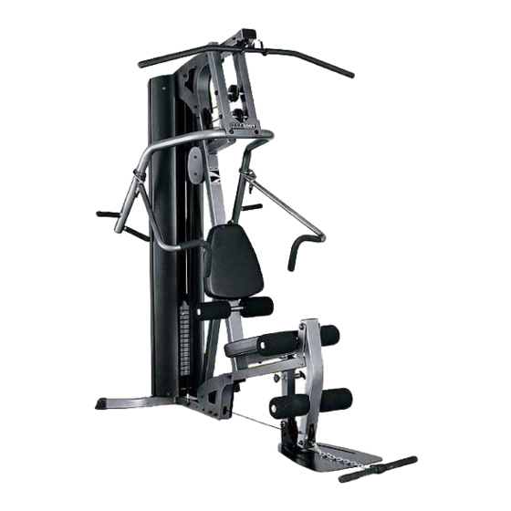
- Page 1 GS1 GYM SYSTEM USER’S GUIDE CLASS H PART # 7597201 REV. A WARNING: Read and follow all directions for each step to insure proper assembly of this product. Version: GS1-103 Revision: 07/30/03...
- Page 2 Use only the pin provided by the manufacturer. If unsure, call your authorized ParaBody dealer. NOTE: In a continual effort to improve our products, specifications are subject to change 2002 Life Fitness, a division of Brunswick Corporation. All rights reserved. © ParaBody is a trademark of Brunswick Corporation www.parabody.com...
-
Page 3: Tools Required For Assembly
Please note: * Thank you for purchasing the ParaBody GS1 Gym System. Please read these instructions thoroughly and keep them for future reference. * This product must be assembled on a flat, level surface to assure its proper function. DO NOT securely tighten any frame connections until the entire frame has been assembled, unless otherwise stated. - Page 4 1’ 2’ 1’ 2’ 3’ 4’ 5’ 6’ 7’ 1 Square = 1’ X 1’ Minimum Required Usable Space Length Width Height Dimensions Including LP5 Leg Press (optional) Length Width 4’ 3’ 5’ = 82 inches (208.5 cm) 6’ 10” = 71 inches (180.5 cm) 5’11”...
-
Page 5: Parts List
PART # DESCRIPTION ACU04-1163 ACU04-1158 BASE PLATE ACU02-1060 ACU04-1160 BOOM PLATE LEFT ACU04-1384 BOOM PLATE RIGHT ACU04-1344 FRAME BRACE ACU04-1100 FOOT PLATE PRESS ARM ACU04-1098 ACU04-1159 PRIMARY PIVOT ACU04-1162 SEAT ADJUST ACU04-1157 LEG PEDESTAL PULLEY PLATE ACU02-1071 ACU07-0135 SEAT/BACK PAD ACU01-1782 3/4 X 17”... - Page 6 3/8 X 3-3/4 FIGURE 1 STEP 1: • LOOSELY assemble two BASE PLATES (3) to the FRAME (1) and BASE (2) using four 3/8 X 3-3/4” BOLTS (30) and four 3/8” LOCK NUTS (34). See FIGURE 1. • LOOSELY assemble the FOOTPLATE (7) to the lower holes in the FRAME (1) using one 3/8 x 3” BOLT (29) and one 3/8 LOCKNUT (34) •...
- Page 7 FIGURE 2 • CHECK THAT THE HEADPLATE AND WEIGHT PLATES ARE ASSEMBLED AS SHOWN IN FIGURES 2 & 3 FIGURE 3...
- Page 8 STEP 4: • Insert two GUIDE RODS (16) into the BASE (2) as shown on FIGURE 4. (NOTE: If the GS1 SHROUD OPTION was purchased, place the GUIDE RODS (16) through the BOTTOM SHROUD BRACKET (FOUND IN THE SHROUD KIT BOX) into the BASE (2), as shown in FIGURE 4.
- Page 9 3/8 X 3” TIGHTEN 20lbs/ft PUSH FORWARD AND HOLD FIGURE 6 STEP 6: • Place PRESS ARM (8) into PRIMARY PIVOT (9) and insert two 3/8 X 3” BOLTS (29), and two 3/8” FLAT WASHERS (36). While Pushing the PRESS ARM (8) forward, securely tighten the two 3/8 x 3” BOLTS (29) to 20 LBS/FT of torque using two 3/8”...
- Page 10 1/2 X 8-3/4” FIGURE 7 STEP 7: • SECURELY TIGHTEN ALL FRAME CONNECTION BEFORE PROCEEDING TO NEXT STEP • SECURELY TIGHTEN top of both SHAFT COLLARS (48) flush to bottom of both BOOM PLATES (4),(5) • Insert 3/4 x 4” SHAFT (40) into both 3/4” FLANGE BEARINGS on FRAME (1) •...
- Page 11 3/8 X 3” FIGURE 8 STEP 8: • Apply WEIGHT STACK LABELS (49) to WEIGHTS (22) and HEAD PLATE (19) as shown in FIGURE 8. Begin with number one at the HEAD PLATE (19) with larger numbers in consecutive order towards bottom of weight stack. •...
- Page 12 STEP 9: • Assemble the LEG PEDESTAL (11) to the FRAME (1) using one 1/2 X 104mm BOLT (32), two RH WASHERS (56) and one 1/2” LOW HT LOCK NUT (35) • Assemble two RH CAPS (55) to the 1/2” RH WASHERS (56) as shown in FIGURE 9 STEP 10: •...
- Page 13 ILLUSTRATION A • ILLUSTRATION “A” used as cable routing reference for steps 12-15 NOTE: IF YOU PURCHASED A LEG PRESS, PLEASE REFER TO THE CABLE ROUTING INSTRUCTIONS INCLUDED WITH THE LEG PRESS KIT...
- Page 14 3/8 X 8-3/4” FIGURE 11 STEP 11: • Refer to cable ILLUSTRATION “A” on page 13 for cable routing while installing pulleys. • Assemble two 3-1/2” PULLEYS (24) into FRAME (1) using two 3/8 X 3-3/4” BOLTS (30), four 3/8 X 1-1/16” FLANGE SPACERS (42) and two 3/8”...
- Page 15 3/8 X 3-3/4” 3/8 X 8-3/4” FIGURE 12 STEP 12: • Refer to cable ILLUSTRATION “A” on page 13 for cable routing while installing pulleys. • Assemble one 3-1/2” PULLEY (24) into the PRIMARY PIVOT (9) lower hole using one 3/8 X 8-3/4” BOLT (31), two 3/8”...
- Page 16 FIGURE 13 STEP 13: • Slip ring of WEIGHT SELECTOR PIN (51) down WEIGHT STACK SHAFT and insert pin into one of the weights • Screw end of LAT CABLE (20) into top of PLATE SHAFT (18) and securely tighten JAM NUT as shown in FIGURE 13 •...
- Page 17 3/8 x 3” 29 3/8 x 3-3/4” FIGURE 14 STEP 14: • Refer to cable ILLUSTRATION “A” on page 13 for cable routing while installing pulleys. • [CABLE MUST BE POSITIONED BETWEEN PULLEY AND LOWER BOLT ASSEMBLY ON LEG PEDESTAL (11) AND FRAME (1)] •...
- Page 18 3/8 X 1 -3/4” 3/8 X 3-3/4” FIGURE 15 STEP 15: • Refer to cable ILLUSTRATION “A” on page 13 for cable routing while installing pulleys. • Assemble one 3-1/2” PULLEY (24) between BASE PLATES (3) using one 3/8 X 3-3/4” BOLT (30), two 3/8 X 1” SPACERS (43), one 3/8”...
- Page 19 FIGURE 16 STEP 16: • Attach two 4 X 7” ROLLER PADS (15) to the LEG PEDESTAL (11) using one 3/4 X 17” TUBE (14) and two 3/4” STARLOCK COLLARS (54) as shown in FIGURE 16. • Attach two 4 X 7” ROLLER PADS (15) to the SEAT ADJUST (10) using one 3/4 X 17-1/2” TUBE (18), two PLASTIC WASHERS (39) and two 3/4”...
- Page 20 • Attach the ANKLE STRAP (25) to the 12 LINK CHAIN (26) using two SNAP LINKS (57) as shown in FIGURE 17 Thank you for purchasing the ParaBody GS1 Gym System. If unsure of proper use of equipment, call your local ParaBody distributor or call the ParaBody customer service department at (800) 328-9714...
- Page 21 YOU MAY NEED SERVICE YOU WILL BE ASKED FOR THIS INFORMATION. REMEMBER TO FILL OUT YOUR WARRANTY REGISTRATION CARD AND MAIL BACK. SERIAL NUMBER LOCATED ON PULLEY BRACKET Thank you for purchasing the ParaBody GS1 Gym System. MAINTENANCE MODEL #________________________ SERIAL #_________________________ DATE OF PURCHASE: _____________...
-
Page 22: Limited Warranty
ParaBody extends the following LIMITED WARRANTY to the original owner of the ParaBody products. The Warranty terms apply to IN HOME USE ONLY. 1. LIMITED WARRANTY ON FRAME AND WELDS. If the frame of the ParaBody product or a weld should crack or break, it will be repaired or replaced by ParaBody. - Page 23 Life Fitness Italia S.R.L. Via Elvas 92 39042 Bressanone Italy Phone: 39 (472) 835-470 Fax: 39 (472) 833-150 Life Fitness Asia Pacific Limited Room 2610, Miramar Tower 132 Nathan Road, Tsimshatsui Kowloon, Hong Kong Phone: (852) 2891-6677 Fax: (852) 2575-6001 www.parabody.com...