
Related Manuals for AIRLESSCO Spray & Stripe 3600


Summary of Contents for AIRLESSCO Spray & Stripe 3600
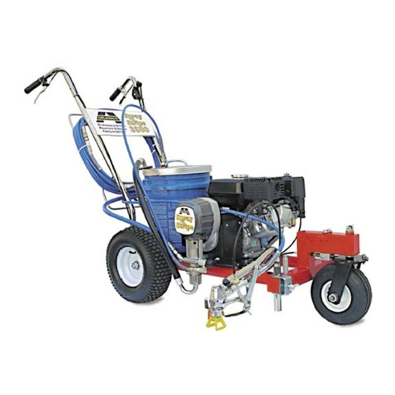
- Page 1 SERVICE/OPERATION Spray & Stripe Spray & Stripe Spray & Stripe Spray & Stripe MANUAL MANUAL 001-778 AUG07...
-
Page 2: Table Of Contents
Table of Contents INTRODUCTION Spray & Stripe Specifi cations Safety Warnings GETTING STARTED Flushing Daily Maintenance Pressure Relief Procedure Setting Up to Stripe or Spray Starting Up Striping Operation REPAIRS/MAINTENANCE INSTRUCTIONS Spray Gun Operation Spray Gun Troubleshooting Field Troubleshooting Servicing the Fluid Pump Servicing the Piston Rod Servicing the Suction Assembly Packing Replacement... -
Page 3: Introduction
Engine Service Level IMPORTANT WARNING !! OBSERVE ALL WARNINGS! understand all warnings on pages 2 thru 6. 305-385 Airlessco Spray & Stripe 3600 305-380 ALLPRO Spray & Stripe 3000 PSI (170 Bar) 0.7 GPM (2.65 Litres/min.) 1 gun @ 0.025”... -
Page 4: Safety Warnings
Safety Warnings TOXIC FLUID HAZARD Hazardous fluid or toxic fumes can cause serious injury or death if splashed in eyes or on skin, inhaled or swallowed. Know the hazards of the fluid you are using. Store & dispose of hazardous fluids according to manufacturer, local, state & national guidelines. - Page 5 Safety Warnings HIGH PRESSURE SPRAY CAN CAUSE EXTREMELY SERIOUS INJURY. INJECTION HAZARD Fluids under high pressure from spray or leaks can penetrate the skin and cause extremely serious injury, including the need for amputation. • NEVER point the spray gun at anyone or any part of the body. •...
- Page 6 Safety Warnings GROUNDING Ground the sprayer and other components in the system to reduce the risk of static sparking, fire or explosion which can result in serious bodily injury and property damage. Always ground all of these components: • Fluid Hose: use only grounded hoses. •...
- Page 7 Safety Warnings FLUSHING Reduce risk of injection injury, static sparking or splashing by following the specific cleaning procedure on page 7. • ALWAYS follow the PRESSURE RELIEF PROCEDURE on page 10. • ALWAYS remove the spray tip before flushing. Hold a metal part of the gun firmly to the side of a metal pail and use the lowest possible fluid pressure during flushing.
- Page 8 Safety Warnings WHEN TRANSPORTING EQUIPMENT • Transport with fuel tank EMPTY or with fuel shut-off valve OFF. WHEN STORING GASOLINE OR EQUIPMENT WITH FUEL IN TANK • Store away from furnaces, stoves, water heaters and other appliances that have pilot lights or other ignition source.
-
Page 9: Flushing
Flushing Read prior to using your sprayer 1. New Sprayer Your Airlessco unit was factory tested in an antifreeze solution which was left in the pump. Before using oil-base paint, flush with mineral spirits only. Before using water-base paint flush with soapy water, then do a clean water flush. 2. -
Page 10: Daily Maintenance
Daily Maintenance 1. Keep the displacement pump packing nut/wet cup lubricated with Airlessco TSO (Throat Seal Oil) at all times. The TSO helps protect the rod and the packings. 2. Inspect the packing nut daily. Your pump has Airlessco’s patented Triple Life Packing System. Packing life will be extended a minimum of three times if the following "Packing Adjustment"... -
Page 11: Pressure Relief Procedure
Pressure Relief Procedure IMPORTANT! To avoid possible serious body injury, always follow this procedure whenever the sprayer is shut off, when checking it, when installing, changing or cleaning tips, whenever you stop spraying, or when you are instructed to relieve the pressure. 1. -
Page 12: Setting Up To Stripe Or Spray
Setting Up to Stripe or Spray 1. Connect the hose and gun. a. If the hose is not already installed on the striper, remove the plastic cap plug from the outlet tee at the spray pump, and screw a conductive or grounded 3000 psi airless spray hose onto fl uid outlet. -
Page 13: Starting Up
Starting Up 1. Learn the Functions of the Controls. PRIME/PRESSURE (PR) RELIEF VALVE is used to prime pump and to relieve pressure from gun, hose and tip. (Prime/PR Valve) Prime/Pressure Relief Valve Used to relieve pressure from gun, hose & tip and to prime the unit when in OPEN position. - Page 14 Starting Up 5. When Shutting off the Sprayer a. Whenever you stop spraying, even for a short break, follow the "Pressure Relief Procedure". b. Clean the tip & gun as recommended in the seperate Gun Manual supplied with the gun/ c.
-
Page 15: Striping Operation
Striping Operation 1. Choose handle location The choices are, installing the handle opposite of the single wheel assembly (standard set up) or placing the handle directly over the single wheel assembly. The handle location is really a matter of personal preference, however having the handle away from the single wheel assembly allows for easier loading/ unloading from a van or truck. -
Page 16: Spray Gun Operation
Spray Gun Operation SPRAY GUN Attach spray gun to airless unit and tighten fittings securely. Set the gun safety latch. (Also may be called gun safety lock, or trigger lock) * The gun safety latch should always be set when the gun is not being triggered. -
Page 17: Spray Gun Troubleshooting
Spray Gun Troubleshooting DEFECTS Coarse spray Excessive fogging (overspray) Pattern too wide Pattern too narrow Too much material Too little material Thin distribution in center of pattern "horns" Thick skin on work Coating fails to close & smooth over Spray pattern irregular, deflected Craters or pock marks Bubbles on work... -
Page 18: Field Troubleshooting
Field Troubleshooting PROBLEM Unit doesn't prime Unit primes but has no or poor pressure Unit does not maintain good spraying pressure CAUSE Airleak due to: • Loose Suction Nut • Worn O-Rings • Hole in Suction Hose Stuck or Fouled Balls Pressure set too low Filter(s) are clogged Outlet Valve fouled/worn... -
Page 19: Servicing The Fluid Pump
Servicing the Fluid Pump Fluid Pump Disconnect Refer to Figure 1 1. Follow the Pressure Relief Procedure on page 10. 2. Flush the material you are spraying out of the machine. 3. Remove the connecting rod shield (331-111). 4. Move the piston rod (331-093) to its lowest position by cycling pump slowly. -
Page 20: Servicing The Piston Rod
Servicing the Piston Rod - Outlet Valve DISASSEMBLY OF THE OUTLET VALVE REFER TO FIGURE 3 1. Disconnect the Fluid Pump following instructions on page 17 . 2. Place piston holder (331-195) in a vise. Slide piston into the holder & lock in place with a 3/8” dowel (331-196). 3. -
Page 21: Packing Replacement
Packing Replacement Procedures Replacement Instructions: Fluid Pump Removal - Refer to Figure 1 1. Follow the Pressure Relief Procedure on page 9. 2. Flush material you are spraying out of the machine. 3. Remove the connecting rod shield (331-111). 4. Move the piston rod (331-093) to its lowest position by cycling pump slowly. - Page 22 Packing Replacement Procedures 3. Push the two bolts (100-318) through the tube spacers (331-074) & screw into the cover assembly (331-234). Using a 1/2” wrench, tighten the two bolts evenly (alternating between them) until you reach 20 ft-lbs. 4. Reassemble lower suction valve assembly by placing the suction seat (331-409) O-ring (106-011), suction ball (331-030) and suction ball guide (331-029) in the suction nut (331-034) &...
-
Page 23: Elect. Control Board Replacement
Electrical Control Board Replacement 1. Remove electrical cover. 2. Disconnect sensor lead from Electrical Board. 3. Disconnect two clutch leads on Electrical Board from leads on clutch. 4. Using a 1/16" allen, loosen set screw in Pressure Con trol Knob and remove knob. Pressure Calibration on the Electrical Control Board 1. -
Page 24: Clutch Replacement
Clutch Replacement REMOVE CLUTCH AS FOLLOWS: 1. Remove clutch and electrical box cover. 2. Disconnect the power lead coming from the engine to the electrical box and feed it through the back of the electrical box. 3. Using a 1/2” wrench along with a 1/2” socket remove the four bolts attaching the engine to the frame. -
Page 25: Cltuch Troubleshooting
(black) from the engine magneto lead (pink), located on the side of the engine. With the engine at maximum RPM (3600), pressure control knob in maximum (CW) position and prime valve open (priming), read the AC voltage from the magneto lead to the sprayer frame. This reading should be 19-24 VAC. -
Page 26: Gearbox Assembly
Ball Bearing 331-209 Shaft Pinion 331-407 Machined End Bell 331-537 Crosshead Ass’y * Not Shown Ball Bearing 331-132 Description Ball Bearing Sleeve Bearing Retaining Ring Spacer Flat Washer Front Shield Sleeve FLPHHD Screw Pait Pump Ass’y Crank Ass’y Machined Cover Grease... -
Page 27: Spray Gun Assembly
Rev- Tip Seal 563-317ST Striping Tip 560-517 Painting Tip (not installed) Gun Mount Assembly - Part Number Description 100-342 .321 x 1.25 LG. Screw 116-100 Compression Spring 119-049 HexScrew .25-20UNC-2A x 1.88 119-050 Screw Pan HD 119-052 Hex Lock Nut 136-217 Jam Nut .250 nylon locking... -
Page 28: Frame Assembly
Frame Assembly 301-533 Paint Bucket Lid... -
Page 29: Swivel Wheel Assembly
Swivel Wheel Assembly Suction Assembly Part No. 331-290 Part Number 106-020 Teflon O-Ring 141-015 Hose Clamp 331-034 Suction Nut 331-035 Suction Elbow 331-217 Suction Filter Description Qty. (some models only) -
Page 30: Striping Tip Guide
Striping Tip Guide Striping Tips should not be used for regular spraying. Striping tips are designed for a single pass application, while spray tips are designed for the 1/3 overlap technique used for spray painting. Spray Tip Replacement: During use high pressure will cause the orifice to grow larger. This destroys the flat spray pattern or will leave tailing or two heavy lines on the outside of the pattern. -
Page 31: Accessories
Strong yet flexible, suitable for airless equipment up to 3300 PSI Part No: 100-012 3/16” Whip Hose, 4 Ft. 100-011 1/4” Hose, 50 Ft. 100-023 3/8” Hose, 50 Ft. 100-037 1/2” Hose, 50 Ft. 100-010 1/4" Hose Connector 100-009 3/8" Hose Connector 032-012 "F to G"... - Page 32 2. Lock trigger open with the Easy to install & align! supplied washer. 3. Turn on water fl ow to backfl ush paint into the original bucket for reuse while cleaning gun, hose, and pump.