Motorola ASTRO XTS 1500 User Manual
Hide thumbs
Also See for ASTRO XTS 1500:
- User manual (82 pages) ,
- Manual (2 pages) ,
- Service manual (914 pages)
Table of Contents
Advertisement
Advertisement
Chapters
Table of Contents

Related Manuals for Motorola ASTRO XTS 1500


Summary of Contents for Motorola ASTRO XTS 1500
-
Page 5: Declaration Of Conformity
FCC logo shown below. DECLARATION OF CONFORMITY Per FCC CFR 47 Part 2 Section 2.1077(a) Responsible Party Name: Motorola, Inc. Address: 1301 E. Algonquin Rd, Schaumburg, IL 60196-1078 USA Phone Number: 1-800-927-2744 Hereby declares that the product: Model Name: XTS 1500 conforms to the following regulations: FCC Part 15, subpart B, section 15.107(a), 15.107(d) and section 15.109(a) -
Page 6: Product Safety And Rf Exposure Compliance
Product Safety and RF Exposure booklet enclosed with your radio (Motorola Publication part number 6881095C98) to ensure compliance with RF energy exposure limits. For a list of Motorola-approved antennas, batteries, and other accessories, visit the following web site which lists approved accessories: http://www.motorola.com/governmentandenterprise/... -
Page 7: Documentation Copyrights
Furthermore, Motorola reserves the right to make changes to any products herein to improve readability, function, or design. Motorola does not assume any liability arising out of the applications or use of any product or circuit described herein; nor does it cover any license under its patent rights, nor the rights of others. - Page 8 Notes ASTRO XTS 1500 Model 1.5...
-
Page 9: Table Of Contents
Contents Contents Declaration of Conformity ..............i Product Safety and RF Exposure Compliance ......... ii Computer Software Copyrights ............ii Documentation Copyrights ..............iii Disclaimer ..................iii General Radio Operation ..........1 Notations Used in This Manual ............1 XTS 1500 Model 1.5 Radio ............... 2 Physical Features of the XTS 1500 Model 1.5 Radio ....... - Page 10 PTT ID .....................37 Transmit ..................37 Trunking System Controls ...............37 Failsoft ..................37 Out-of-Range ................38 Site Lock ...................38 Site View and Change ..............39 Helpful Tips ..............39 Radio Care ..................39 Cleaning ..................39 Handling ..................39 Service .....................40 Battery .....................40 ASTRO XTS 1500 Model 1.5...
- Page 11 Contents Battery Life ................40 Charging the Battery ..............41 Battery Recycling and Disposal ............42 Antenna ................... 43 Radio Operating Frequencies ........... 43 Accessories ..............44 Antennas ..................44 Batteries ..................44 Carry Accessories ................45 Belt Clips .................. 45 Body-Worn ................
- Page 12 Notes viii ASTRO XTS 1500 Model 1.5...
-
Page 13: General Radio Operation
The following special notations identify certain items: Example Description Top button Buttons are shown in bold print. Information appearing in the radio’s display is shown using SELF TEST the special display font. ASTRO XTS 1500 Model 1.5... -
Page 14: Xts 1500 Model 1.5 Radio
General Radio Operation XTS 1500 Model 1.5 Radio... -
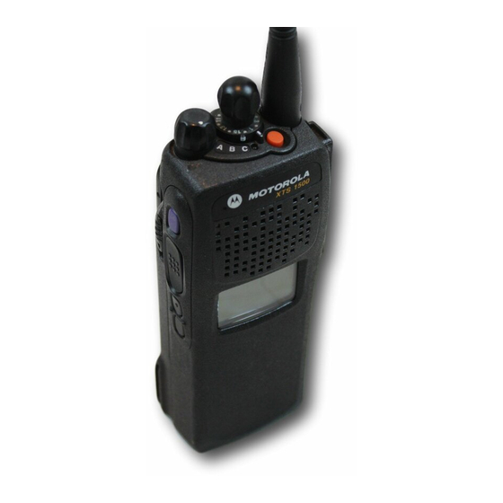
Page 15: Physical Features Of The Xts 1500 Model 1.5 Radio
10 Top Side (Select) (LED) Button (programmable) Speaker 11 Push-to-Talk (PTT) Button Universal Connector 12 Side Button 1 (programmable) Channel Selector 13 Side Button 2 Knob (programmable) (programmable) 3-Position Concentric 14 Battery Switch (programmable) 15 Display ASTRO XTS 1500 Model 1.5... -
Page 16: Programmable Features
General Radio Operation Programmable Features The programmable controls on your radio can be programmed by a qualified technician to operate certain software-activated features. The features that can be assigned to these controls, and the page numbers where these features can be found, are listed below. Table 1: Programmable Features Feature Page... -
Page 17: Display
If poor light conditions make the display difficult to read, turn on the radio’s backlight by pressing the Light button. The light will remain on for a preprogrammed time before it turns off automatically, or you can turn it off immediately by pressing the Light button again. ASTRO XTS 1500 Model 1.5... -
Page 18: Status Symbols
General Radio Operation Status Symbols The top two rows in the display contain symbols indicating the radio’s status. Table 2: Status Symbols Symbol Indication Page Call Received. Blinks when an Individual Call is received. View Mode. View a list. Received Signal Strength Indication (RSSI). The received signal strength for the current site. -
Page 19: Light Emitting Diode (Led) Indicators
Invalid Key-Press pressed. Radio Self-Test when the radio fails the power- Short, Failed up self test. Low-Pitched when an unauthorized request Tone Reject is made. Time-Out Timer four seconds before time out. Warning ASTRO XTS 1500 Model 1.5... - Page 20 General Radio Operation Table 4: Alert Tones (Continued) You hear: Tone Name Heard: when the radio does not No ACK Received receive an acknowledgment. Time-Out Timer after time out. Timed Out when the PTT button is Talk Prohibit/ pressed, and transmissions PTT Inhibit are prevented.
- Page 21 3-Position Rotary Switch. Group of Low Pitched Tones Short, High- when the battery is below the Pitched Tone Low-Battery Chirp preset threshold value. (Chirp) when a landline phone call is Ringing Phone Call Received received. ASTRO XTS 1500 Model 1.5...
-
Page 22: Standard Accessories
Prior to using a new battery, charge it for a minimum of 16 hours to ensure optimum capacity and performance. For a list of Motorola approved batteries available for use with your XTS 1500 radio, see “Batteries” on page 44. - Page 23 Remove the Battery With the radio off, slide down the latches on the sides of the battery. Pull the top of the battery away from the radio. ASTRO XTS 1500 Model 1.5...
- Page 24 General Radio Operation Smart Battery Condition This feature allows you to view the condition of your Smart Battery. Press the Smart Battery CAPACITY button. INIT 10/01 EST CHGS Note: If a Smart Battery is not SMART BATT powering your radio: DATA NOT AVAILABLE Press the Smart Battery button again to exit.
-
Page 25: Antenna
For information regarding other available antennas, see page 44. Attach the Antenna With the radio off, turn the antenna clockwise to attach Remove the Antenna With the radio off, turn the antenna counterclockwise to remove it. ASTRO XTS 1500 Model 1.5... -
Page 26: Belt Clip
General Radio Operation Belt Clip Attach the Belt Clip Align the grooves of the belt clip with those of the battery. Press the belt clip downward until you clear a “click.” Remove the Belt Clip Use a flat-bladed screwdriver to press the belt clip tab away from the battery. -
Page 27: Universal Connector Cover
Insert the hooked end of the cover into the top of the connector. Press downward on the cover’s top to seat it into the slot. Press the cover’s lower tab below the connector until it snaps in place. ASTRO XTS 1500 Model 1.5... -
Page 28: Remote Speaker Microphone Adapter
Attach the Adapter With the Motorola side of the adapter facing out, snap the smaller end of the adapter into place in the shroud indent, below the On/Off Volume Control Knob. -
Page 29: Radio On And Off
If the radio continues to fail the power-up test, record the ERROR XX/YY code and contact a qualified service technician. Turn the Radio Off Turn the On/Off/Volume Control knob counterclockwise until it clicks. ASTRO XTS 1500 Model 1.5... -
Page 30: Zones And Channels
General Radio Operation Zones and Channels A zone is a grouping of channels. A channel is a group of radio characteristics, such as transmit/receive frequency pairs. Before you use your radio to receive or send messages, you should select the zone. Select a Zone If a control on your radio has FIRE... -
Page 31: Mode Select Button
Mode Select button.The buttons that are assigned for this feature are labeled in the following picture. Top Button Top Side Button Side Button 1 Side Button 2 ASTRO XTS 1500 Model 1.5... -
Page 32: Receive / Transmit
General Radio Operation Receive / Transmit Radio users who switch from analog to digital radios often assume that the lack of static on a digital channel is an indication that the radio is not working properly. This is not the case. Digital technology quiets the transmission by removing the “noise”... -
Page 33: Use The Preprogrammed Volume Set Button
Release the Volume Set button. Adjust the Volume Control Knob if necessary. Press and hold the PTT button to transmit. LED lights RED while transmitting. Release the PTT button to receive (listen). ASTRO XTS 1500 Model 1.5... -
Page 34: Use The Preprogrammed Monitor Button
General Radio Operation Use the Preprogrammed Monitor Button Turn the radio on and select the desired zone and channel. Press the Monitor button and listen for activity. (See the following Conventional Mode Operation.) Adjust the Volume Control knob if necessary. Press and hold the PTT button to transmit. -
Page 35: Conventional Mode Operation
Press the Monitor button again, or the PTT button, to return to the original squelch setting. Note: If you try to transmit on a receive-only channel, you will hear an invalid tone until you release the PTT button. ASTRO XTS 1500 Model 1.5... - Page 36 General Radio Operation Notes...
-
Page 37: Common Radio Features
Defeat position. You can now hear any activity on the channel. The radio is muted if no activity is present. When this feature is active, the Carrier Squelch status indicator ( ) will be displayed. ASTRO XTS 1500 Model 1.5... -
Page 38: Time-Out Timer
Common Radio Features Time-Out Timer The time-out timer turns off your radio’s transmitter. The timer is set for 60 seconds at the factory, but it can be programmed from 0 to 7.75 minutes (465 seconds) by a qualified radio technician. Hold down the PTT longer •... -
Page 39: Emergency
If the selected channel does NO EMERGENCY not support emergency, the display shows NO EMERGENCY. Select a channel that does show EMERGENCY. Note: To exit emergency at any time, press and hold the Emergency button for about a second. ASTRO XTS 1500 Model 1.5... -
Page 40: Send An Emergency Call
Common Radio Features When you receive the ACK RECEIVED dispatcher’s • Four tones acknowledgment, you see • Alarm ends ACK RECEIVED, four tones sound, the alarm ends, and • Radio exits emergency the radio exits the emergency mode. If no acknowledgement is NO ACKNOWLDG received, you see NO ACKNOWLDG, the alarm ends,... - Page 41 • If the new channel is NOT programmed for Emergency, an invalid tone sounds until you exit the Emergency state or change to a channel programmed for emergency. ASTRO XTS 1500 Model 1.5...
-
Page 42: Scan
Common Radio Features Scan The scan feature allows you to monitor traffic on different channels by scanning a preprogrammed list of channels. The list must be preprogrammed by a qualified technician. Turn Scan On and Off Place the Scan On/Off switch in the On or Off position. -
Page 43: Delete A Nuisance Channel
Note: You cannot delete priority channels or the designated transmit channel. The radio continues scanning the remaining channels in the list. To resume scanning the deleted channel, change channels or turn scan off and then back on again. ASTRO XTS 1500 Model 1.5... -
Page 44: Conventional Scan Only
Common Radio Features Conventional Scan Only Make a Dynamic Priority Change While the radio is scanning, the dynamic priority change feature lets you temporarily change any channel in a scan list (except the priority- one channel) to the priority-two channel. The replaced priority-two channel becomes a non-priority channel. -
Page 45: Telephone Calls (Trunking Only)
20 seconds after the call indicators begin. Press and hold the PTT button to talk; release it to listen. Press the Call Response button again to hang up and return to the home display. ASTRO XTS 1500 Model 1.5... -
Page 46: Private Calls (Trunking Only)
Common Radio Features Private Calls (Trunking Only) These one-to-one calls between two radios are not heard by others in the current talkgroup. The calling radio automatically verifies that the receiving radio is active on the system and that it can display the caller’s ID. -
Page 47: Call Alert Paging
LED blinks GREEN, the • Four repeating alert tones call-received symbol ( ) • Blinking GREEN LED blinks, and PAGE RECEIVED is displayed. Press and hold the PTT button to talk, release it to listen. ASTRO XTS 1500 Model 1.5... -
Page 48: Repeater Or Direct Operation
Common Radio Features Repeater or Direct Operation Also known as TALKAROUND operation, DIRECT lets you bypass the repeater and connect directly to another radio. The transmit and receive frequencies are the same. REPEATER operation increases the radio’s range by connecting with other radios through a repeater. -
Page 49: Special Radio Features
Your radio’s ID FAILSOFT predetermined frequency. You hear a medium-pitched tone • Medium-pitched tone every 10 seconds. When the trunking system returns to normal operation, your radio automatically leaves failsoft operation and returns to trunked operation. ASTRO XTS 1500 Model 1.5... -
Page 50: Out-Of-Range
Special Radio Features Out-of-Range If you go out of the range of the system, and can no longer lock onto a control channel: The display shows OUT OF RANGE Your radio’s ID OUT OF RANGE and the currently selected zone/ channel combination, and/or you AND/OR hear a low-pitched tone. -
Page 51: Site View And Change
You hear a tone, and the • Tone display shows SCANING SITE while the radio scans SCANING SITE for a new site. The radio returns to the home display when it finds a new site. ASTRO XTS 1500 Model 1.5... - Page 52 Special Radio Features Notes...
-
Page 53: Helpful Tips
Avoid subjecting the radio to corrosives, solvents or spirits. • Do not disassemble the radio. • Keep the accessory-connector cover in place until ready to use the connector. Replace the cover immediately once the accessory has been disconnected. ASTRO XTS 1500 Model 1.5... -
Page 54: Service
Helpful Tips Service Proper repair and maintenance procedures will assure efficient operation and long life for this product. A Motorola maintenance agreement will provide expert service to keep this and all other communication equipment in perfect operating condition. A nationwide service organization is provided by Motorola to support maintenance services. -
Page 55: Charging The Battery
Helpful Tips Charging the Battery Motorola batteries are designed specifically to be used with a Motorola charger and vice-versa. Charging in non-Motorola equipment may lead to battery damage and void the battery warranty. Motorola-authorized battery chargers may not charge batteries other than the ones listed on page 44. -
Page 56: Battery Recycling And Disposal
Motorola fully endorses and encourages the recycling of NiCd batteries. In the U.S. and Canada, Motorola participates in the nationwide Rechargeable Battery Recycling Corporation (RBRC) program for NiCd battery collection and recycling. Many retailers and dealers participate in this program. -
Page 57: Antenna
800 MHz whip, 806–870 NAF5037 halfwave 900 MHz whip, BLUE 896–941 NAF5038 halfwave 800 MHz dipole 806–870 NAF5039 900 MHz dipole BLUE 896–941 NAF5040 800/900 MHz WHITE 806–941 NAF5042 stubby, quarterwave 700/800 MHz whip GREEN 764–870 NAF5080 ASTRO XTS 1500 Model 1.5... -
Page 58: Accessories
Accessories Accessories Motorola provides the following approved accessories to improve the productivity of your XTS 1500 portable two-way radio. For a list of Motorola-approved antennas, batteries, and other accessories, visit the following web site which lists approved accessories: http://www.motorola.com/governmentandenterprise/ Antennas NAD6563 VHF whip (136–174 MHz) -
Page 59: Carry Accessories
* Batteries include an over-discharge protection circuit (similar to those in Li-Ion batteries) to extend life of batteries by preventing excessive battery discharge during customer use. Motorola strongly recommends charging these batteries with Motorola-approved IMPRES desktop charges programmed with version 3.4 of the IMPRES desktop charger software. -
Page 60: Enhanced And Multi-Unit Line Cords
Accessories NTN1169 Single-unit dual rate, rapid charger 220V (2-prong Euro plug) NTN1170 Single-unit dual rate, rapid charger 240V (3-prong UK plug) NTN1177 Multi-unit, dual rate, rapid charger 110V NTN1178 Multi-unit, dual rate, rapid charger 240V (3-prong UK plug) NTN1179 Multi-unit, rapid charger 240V (UK 13 MAP Plug) NTN1667 Tri-chemistry, 110V NTN1668... -
Page 61: Surveillance Accessories
CommPort with palm PTT NTN1625 CommPort ear mic with PTT for noise levels up to 100 dB (requires BDN6676 adapter) NTN1663 CommPort ear mic with ring PTT for noise levels up to 100 dB (requires BDN6676 adapter) ASTRO XTS 1500 Model 1.5... -
Page 62: Earpieces
Accessories NTN1736 CommPort ear mic with snap-on side PTT for noise levels up to 100 dB (requires BDN6676 adapter) Earpieces BDN6641 Ear mic, high noise level up to 105 dB, grey (must order BDN6671 interface module) BDN6664 Earpiece with standard earphone, beige BDN6665 Earpiece with extra-loud earphone (exceeds OSHA limits), beige... -
Page 63: Headsets And Headset Accessories
Push-to-talk (PTT) and voice-activated (VOX) interface module (for use with BDN6641, BDN6677 and BDN6678) BDN6708 PTT interface module (for use with BDN6641, BDN6677 and BDN6678) Switches 0180300E83 Remote PTT body switch NTN7660 Tilt / Man down switch ASTRO XTS 1500 Model 1.5... - Page 64 Accessories Notes...
-
Page 65: Appendix: Maritime Radio Use In The Vhf Frequency Range
10 Wait for a response. 11 If you do not receive an immediate response, remain by the radio and repeat the transmission at intervals until you receive a response. Be prepared to follow any instructions given to you. ASTRO XTS 1500 Model 1.5... -
Page 66: Non-Commercial Call Channel
Appendix: Maritime Radio Use in the VHF Frequency Range Non-Commercial Call Channel For non-commercial transmissions, such as fishing reports, rendezvous arrangements, repair scheduling, or berthing information, use VHF Channel 9. Operating Frequency Requirements A radio designated for shipboard use must comply with Federal Communications Commission Rule Part 80 as follows: •... - Page 67 161.500 156.950 161.550 157.000 161.600 157.050 161.650 157.100 161.700 157.150 161.750 157.200 161.800 157.250 161.850 157.300 161.900 157.350 161.950 157.400 162.000 156.025 160.625 156.075 160.675 156.125 160.725 156.175 160.775 156.225 160.825 156.275 160.875 156.325 160.925 ASTRO XTS 1500 Model 1.5...
- Page 68 Appendix: Maritime Radio Use in the VHF Frequency Range Table A-1: VHF Marine Channel List (Continued) Frequency (MHz) Channel Number Transmit Receive 67** 156.375 156.375 156.425 156.425 156.475 156.475 156.575 156.575 156.625 – 156.675 156.675 156.725 156.725 77** 156.875 – 156.925 161.525 156.975...
-
Page 69: Glossary
A channel that has traffic on it. Analog Signal An RF signal that has a continuous nature rather than a pulsed or discrete nature. ASTRO 25 Trunking Motorola standard for wireless digital trunked communications. ASTRO Motorola standard for wireless analog or Conventional digital conventional communications. - Page 70 Glossary Digital Private Line A type of coded squelch using data bursts. (DPL) Similar to PL except a digital code is used instead of a tone. Digital Signal An RF signal that has a pulsed, or discrete nature, rather than a continuous nature. Dispatcher An individual who has radio system management duties.
- Page 71 Push-To-Talk – the PTT button engages the transmitter and puts the radio in transmit (send) operation when pressed. Radio Frequency The part of the general frequency spectrum (RF) between the audio and infrared light regions (about 10 kHz to10,000,000 MHz). ASTRO XTS 1500 Model 1.5...
- Page 72 Glossary Repeater A conventional radio feature, where you talk through a receive/transmit facility (repeater), that re-transmits received signals in order to improve communications range and coverage. Selective Switch Any digital P25 traffic having the correct Network Access Code and the correct talkgroup.
-
Page 73: Commercial Warranty
Product Accessories One (1) Year Motorola, at its option, will at no charge either repair the Product (with new or reconditioned parts), replace it (with a new or reconditioned Product), or refund the purchase price of the Product during the warranty period provided it is returned in accordance with the terms of this warranty. - Page 74 Commercial Warranty MOTOROLA cannot be responsible in any way for any ancillary equipment not furnished by MOTOROLA which is attached to or used in connection with the Product, or for operation of the Product with any ancillary equipment, and all such equipment is expressly excluded from this warranty.
- Page 75 Product item, transportation and insurance prepaid, to an authorized warranty service location. Warranty service will be provided by Motorola through one of its authorized warranty service locations. If you first contact the company which sold you the Product, it can facilitate your obtaining warranty service.
- Page 76 A) that MOTOROLA will be notified promptly in writing by such purchaser of any notice of such claim; B) that MOTOROLA will have sole control of the defense of such suit and all negotiations for its settlement or compromise; and C) should the Product or parts become, or in MOTOROLA’s...
- Page 77 MOTOROLA, nor will MOTOROLA have any liability for the use of ancillary equipment or software not furnished by MOTOROLA which is attached to or used in connection with the Product. The foregoing states the entire liability of MOTOROLA with respect to infringement of patents by the Product or any parts thereof.
-
Page 78: Index
Index accessories display .......... 5 antennas .........44 display status symbols ....6 batteries ........44 belt clips ........45 body-worn .......45 emergency carry accessories ....45 send an emergency call ..28 chargers ........45 Commport integrated microphone/receivers ....47 failsoft ......... 37 earpieces .........48 headsets ........49 microphones, remote speaker .....46... - Page 79 ....47 earpieces .........48 headsets and headset accessories ......49 radio interface modules for ear microphones ....49 switches ........49 time-out timer ......26 Trunking System Controls ...37 turn the radio off ......17 turn the radio on ......17 ASTRO XTS 1500 Model 1.5...
- Page 80 Index Notes...