
Related Manuals for Panasonic VF100


Summary of Contents for Panasonic VF100
-
Page 1: Instruction Manual
Inverter VF100 Instruction Manual Panasonic Electric Works Automation http://www.mew.co.jp/ac/c/ Controls (Shanghai) Co., Ltd. -
Page 2: Safety Precautions
Foreword Thank you for purchasing the general-purpose VF100 series inverter produced by Panasonic Electric Works Automation Controls (Shanghai) Co., Ltd. Usage methods and precautions are described in this instruction manual. Read this manual carefully before attempting to operate the inverter and store it for future reference. - Page 3 1. Installation Note Install the unit on a non-combustible material such as metal. Installing it on other material could lead to fires. Do not place the unit near flammable materials. Doing so could lead to fires. Do not hold by terminal cover during transportation. Doing so could cause the unit to drop and lead to injuries.
- Page 4 3. Operation ! Caution Always close the terminal cover before turning the input power ON. Do not open the terminal cover while the power is ON. Doing so could lead to electric shock or fires. Do not operate the switches or buttons with wet hands. Doing so could lead to electric shock.
- Page 5 Note The heat sink fins and brake resistor can reach high temperatures, so do not touch them. Doing so could lead to burns. ¡ñ The inverter can be easily set to run from low speeds to high speeds. Confirm the tolerable range of the motor and machine before starting operation.
-
Page 6: General Precautions
5. Others Caution ¡ñ Never modify the unit. Doing so could lead to electric shock or injury. 6. General Precautions All diagrams in this instruction manual show the state with the cover or safety partitions removed to explain the details. Before operating the product, replace the covers and partitions to the positions specified, and operate the unit according to the instruction manual. -
Page 7: Table Of Contents
Contents 1. Points for Handling 2. Special Precautions 3. Installation 4. Outline Dimensions 5. Parts Identification 5-1. Part Name 5-2. Details on Part Number 5-3. Removal and Installation of Terminal Cover 5-4. Removal and Installation of Operation Panel 5-5. Explanation of Operation Panel 6. -
Page 8: Table Of Contents
Contents 9-2. Functional Descriptions (Parameters Table) 9-3. Functional Descriptions (By Parameters) 10. Custom Mode 10-1. Method of Distributing Function Parameter No. to Custom Parameter No. 10-2. Method of Setting and Changing Function Parameter Data in Custom Mode 11. Setting Mode and Copy Function of Built-in Memory 11-1. -
Page 9: Table Of Contents
Contents 12-7. Function Code for MOD-BUS(RTU) in Inverter 12-8. Common Precautions on MEWTOCOL-COM/MOD-BUS(RTU) 12-8.1 Send/Receive Changeover Wait Time 12-8.2 Processing Time in Inverter 12-8.3 Precautions on Communicating with Host Computer 12-9. Applicable Communication Function in Inverter 12-9.1 Supplementary Explanation of Communication Monitor Function 12-9.2 Supplementary Explanation of Communication Control/Command Function... -
Page 10: Points For Handling
1. Points for Handling Follow this manual and precautions when handling the inverter. Incorrect handling could lead to inhibited operation or a drop operating life. In the worst case, the inverter could be damaged. Use within + 10%, -15% of the tolerable input Power supply voltage range, and with in¡À5% of the tolerable input frequency range. -
Page 11: Special Precautions
¡ôDo not use the inverter for loads other than a motor or for single-phase motors. ¡ôIf parameters are frequently written in, lifetime of non-volatile memory (EEPROM) will be shorten. The maximum writing times of non-volatile memory (EEPROM) used in VF100 is 100,000 times. Therefore, do not write the parameters frequently. - Page 12 ¡ôPrecautions regarding inverter's protection function Various protection functions such as stall prevention, current limiting and overcurrent shut-off are built in the inverter. These protection functions are used to protect the inverter from the sudden abnormal conditions in use, so they are not the control functions to be always used. Therefore, do not use the applications in which those protection functions activate in the normal operating conditions.
-
Page 13: Installation
3. Installation Note Install the inverter on a non-combustible material such as metal. Installing it on other material could lead to fire. Do not place the inverter near flammable materials. Failure to do so could lead to fire. Do not hold the terminal cover during transportation. Failure to do so could cause the inverter to drop and lead to injuries. -
Page 14: Outline Dimensions
4. Outline Dimensions 4£-¦Õ5( Mounting holes) Unit: mm MODE STOP MIN. MAX. 10.5 ¡ñ 3-phase 400V input type Unit: mm Inverter capacity 0.75, 1.5kW 2.2, 3.7kW Note: The cooling fan is mounted on the 1.5kW, 2.2kW or 3.7kW capacities. [Operation panel] MODE STOP MIN. -
Page 15: Parts Identification
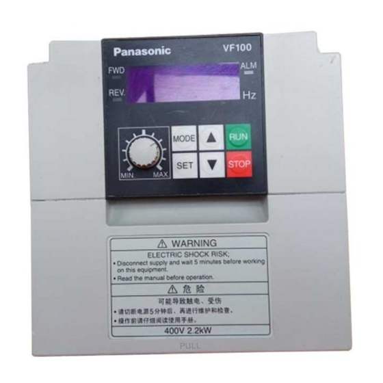
5. Parts Identification 5-1. Part Names Mounting hole Frame Operation panel unit MODE STOP MIN. MAX. Warning label PULL Terminal cover 1 Rating nameplate (Control circuit terminal cover) * Check the rating nameplate to confirm that the ordered product has been delivered. -
Page 16: Details On Part Number
5-2. Details on Part Number A VF100 – 007 4 Input Applicable Voltage class power motor Part Number Series name 4 £º3-phase 400V supply capacity (kW) 0.75 AVF100£-0074 Applicable motor capacity (kW) 3-phase AVF100£-0154 007 £º0.75kW 400V 015 £º1.5kW AVF100£-0224 022 £º2.2kW... -
Page 17: Removal And Installation Of Terminal Cover
5-3. Removal and Installation of Terminal Cover Removal and installation of terminal cover 1 (Control circuit terminal cover) [Removal] ¢Ù Lightly press up the center bottom edge of the terminal cover 1. [Installation] ¢Ú Insert the mounting jaw of terminal cover 1 into the slot on the frame. Lightly press down the center top edge of the terminal cover 1. -
Page 18: Removal And Installation Of Operation Panel
5-4. Removal and Installation of Operation Panel Turn off the power supply before removing the operation panel. Note Removing the operation panel during operation can cause the operation to stop. [Removal] ¢Ù Press up the center top and bottom part of the operation panel vertically to remove it. - Page 19 Inverter side Operation panel side Connector (RJ45) Connector (RJ45) LAN cable LAN cable Installed on the plate (panel) Plate (panel) Unit : mm 2£-¦Õ3.5(Mounting holes) £¼Forward side£¾ £¼Reverse side£¾ Mounting screws(M3) panel cut-out Mounting screws(M3) (18.5) Dimensions of panel cut-out (A view) [Mounting Procedure] 1.
-
Page 20: Explanation Of Operation Panel
5-5. Explanation of Operation Panel Main display FWD display Alarm display (ALM) REV display ¡ø(UP) button MODE button RUN button MODE Frequency setting dial STOP STOP button MAX. MIN. SET button ¡ø(DOWN) button Name of Each Part Description of Functions The output frequency, current, line speed, setting frequency, communication station No., error details, each mode display Main display... -
Page 21: Wiring
6. Wiring 6-1. Wiring (Main Circuit) Caution •I ¡ñ Always confirm that the input power is OFF before starting wiring. Failure to do so could lead to electric shocks or fires. ¡ñ Always connect the earth. Failure to do so could lead to electric shocks or fires. ¡ñ... - Page 22 1. When using regenerative brakes, set the parameter P019 setting data to "0". The brakes will not activate when the factory setting "1" is set. 2. Always use the Panasonic-dedicated option for the brake resistor. 3. The regenerative brake specifications are shown below. Carefully consider the working conditions before using these brakes.
-
Page 23: Wiring( Control Circuit)
6-2. Wiring (Control circuit) Wiring(Control Circuit Terminal) (Common) (Common) Unused RS485 Analog output communication terminal (0¡«10V) 0•` 5V 0•` 10V 0•`5V 0•`10V 4~20mA 200ƒ¶ 0~20mA 4~20mA 200ƒ¶ 0~20mA Relay output (Common) (Common) Open collector output Start Forward SW1 SW2 SW3 SW4 SW5 (TR1¡¢TR2) Stop Reverse... - Page 24 ¡ö Electric Cable Size and Control Circuit Terminal Tightening Torque Tightening torque Wire's insulation Terminal mark Screw size Cable size N•Em removing size 0.25¡«0.75mm A£¬B£¬C 0.5¡«0.6 (AWG24¡«AWG18) 0.25¡«0.75mm ¡« 0.22¡«0.25 (AWG24¡«AWG18) •E Screwdriver: Small-size screwdriver •E Wire's insulation removing size (Depth of the edge: 0.4mm/ Width of the edge: 2.5mm) ¡ö...
- Page 25 ¡ö Explanation of Control Circuit Terminals Terminal Related Parameter Terminal Function RS485 communication transmission line + terminal (D+) P135£-142 RS485 communication transmission line - terminal (D-) P135£-142 RS485 communication transmission line + terminal (D+) P135£-142 RS485 communication transmission line - terminal (D-) P135£-142 RS485 communication terminator terminal (E) P135£-142...
- Page 26 Precautions on Wiring 1. Use shielded wires for all control signal wires and keep them away more than 20cm from power lines and strong electric circuits. 2. Maximum control signal wire length is 30m or less. 3. The control circuit's input signal is a minute signal, so use two minute signal contacts in parallel or use a twin contact to prevent contact faults when inputting the contact.
-
Page 27: Operation( Basic Operation)
7. Operation (Basic Operation) Caution ¡ñ Always close the terminal cover before turning the input power ON. Do not open the terminal cover while the power is ON. Failure to do so could lead to electric shock or fires. ¡ñ Do not operate the switches or dials with wet hands. -
Page 28: Setting The Frequency With The Operation Panel
For VF100, the Following Three Operating Methods Are Available. 1. Operation panel Use buttons and potentiometer on operation panel to operate the inverter. 2. External control operation Use control circuit terminal to operate the inverter (Refer to page 63). 3. Communication (RS485) Use communication command sent by external machine through RS485 to operate the inverter. -
Page 29: Operating With The Operation Panel
Rotation Current state Display Display direction During stop Forward run During forward Reverse run run operation During reverse Current Forward run operation state /reverse Rotation direction setting mode method (Parameter P003 set to "0") In "operation status display mode", press the MODE button twice to enter the "rotation direction setting mode". - Page 30 7-3.1 Operating with the Operation Panel -1 (Factory Setting State) Forward /reverse run function: Rotation direction setting mode method (Parameter P003=0) •EFrequency setting : Potentiometer setting (Parameter P004=0) Example for rotating in forward direction at operating frequency 25Hz The main display lamp will turn ON. Power ON (Operation status display mode) Press the RUN button.
- Page 31 [Continued from previous page.] Press the UP button. (The main display will flicker.) Changing the rotation Press the SET button to set the direction data. (Return to operation status display mode) Press the RUN button. The run state will be entered, but Run command as the frequency setting dial is set to Min., the OV stop state will...
-
Page 32: Operating With The Operation Panel -2
7-3.2 Operating with the Operation Panel - 2 Forward /reverse run function: Forward / reverse run (Parameter P003=1) •EFrequency setting : Potentiometer setting (Parameter P004=0) Example for rotating in forward direction at operating frequency 25Hz The main display lamp will turn ON. Power ON (Operation status display mode) Press the UP button to set rotation... - Page 33 [Example for monitoring and setting potentiometer frequency command before operation] The main display lamp will turn ON. Power ON (Operation status display mode) Press the MODE button. MODE Press the SET button and check thefrequency command. Confirming Turn the frequency setting dial and setting clockwise, and set frequency the operating...
- Page 34 [Continued from previous page] Forward Press the RUN button. The motor will gradually Run command decelerate, and will start reverse run at 25Hz again. Reverse Stopping operation Press the STOP button. The motor will start to decelerate Stop command STOP and will stop.
-
Page 35: Operating With The Operation Panel -3
7-3.3 Operating with the Operation Panel - 3 Forward /reverse run function: Rotation direction setting mode (Parameter P003=0) •EFrequency setting : Digital setting (Parameter P004=1) Example for rotating in forward direction at operating frequency 25Hz The main display lamp will turn ON. Power ON (Operation status display mode) Press the MODE button. - Page 36 [Continued from next page] Press the UP and DOWN buttons to display "50.0Hz" on the main display. (The main display will flicker.) Operating frequency setting Press the SET button to set the data. Display will change to the output frequency, and the motor is rotating in forward direction at 50.0Hz.
- Page 37 [Continued from previous page] Press the RUN button. As the frequency is already set to Run command 50Hz, the motor will start rotating in reverse direction at 50.0Hz. Changing from reverse run to forward run during operation MODE Press the MODE button. MODE Press the MODE button.
- Page 38 Example for changing the frequency with the UP and DOWN buttons during operation (MOP function) The operating frequency can be changed with the UP and DOWN buttons during operation. The motor will accelerate or decelerate according to the operation. If the UP button is held down, the operating frequency will increase.
-
Page 39: Operating With The Operation Panel -4
7-3.4 Operating with the Operation Panel -4 Forward / reverse run function: Forward run/reverse run (Parameter P003=1) •EFrequency setting : Digital setting (Parameter P004=1) Example for rotating in forward direction at operating frequency 25Hz The main display lamp will turn ON. Power ON (Operation status display mode) Press the MODE button. - Page 40 [Continued from previous page] Press the UP or DOWN button, Press the UP and DOWN buttons to display "25.0Hz" on the main display. (The main display will flicker.) Operating frequency Press the SET button to set the data. setting The display will change to the output frequency.
- Page 41 [Continued from previous page] Reverse Press the RUN button. The motor will gradually Run command decelerate, and will start forward rotation at 50Hz again. Forward Stopping operation Press the STOP button. The motor will start to decelerate STOP Stop command and will stop.
-
Page 42: Operation Modes
7-4 Operation Modes VF100 has the following seven modes. Reference Mode name Details page Operation status Output frequency and output current are displayed. ¢Ù display mode (The display can be changed with parameter P145.) Digital setting of frequency and frequency command ¢Ú... - Page 43 [Continued from previous page] [Continued from previous page] MODE Rotation direction setting mode •£ •E Press the buttons to change the rotation direction. Press the button to set the data. Mode of monitoring Forward /reverse rotation direction setting command status MODE and control state.
- Page 44 [Continued from previous page] MODE Custom mode The parameter No. is changed. Hold down the button to set the required parameter No.. Custom parameter No. is displayed. As No. display is flickering, •E •£ Press the buttons to set •E buttons can be used •£...
- Page 45 [Continued from previous page] MODE Function setting mode Press the button to change the required set data. •£ •E Press the buttons to change the data. The parameter No. is displayed. Press the button to change the (Copy function No. is displayed data and the next parameter No.
- Page 46 Note •EExcept the digital setting in the frequency setting mode (P004: frequency signal setting = 1), command frequency of parameter P004 is displayed. •EExcept operating method of the rotation direction setting mode in the rotation direction setting mode (P003: run command select =0), setting cannot be changed only through monitoring.
-
Page 47: Control State Monitor
8. Control State Monitor The following 23 items can be monitored in the control state monitor mode. Monitor Reference Unit Monitor item Indication page n001 Output frequency Output frequency n002 Output current Output current n003 Output voltage Output voltage n004 Internal DC voltage Internal DC voltage n005... - Page 48 n005£ºSetting frequency Indicates the setting frequency of the inverter. n006£ºCommunication station No. Indicates the set communication station No.. Communication station No. can be set with P136: communication station No. setting. n007£ºTimer runtimes In timer's multi speed operation, timer's acceleration and deceleration linking operation, pulse input multi speed operation and pulse input acceleration and deceleration linking operation, runtimes in a cycle during each operation are displayed.
- Page 49 n009£ºControl terminal state (input signal) n010£ºControl terminal state (output signal) Monitor n009 and n010 indicate statuses of the input and output signals of the control circuit terminal. Segment data a1~g1 light when input terminals (¢Ú¡«¢à)and common terminal (¢Ùor¢á) are ON, and light out when these terminals are OFF. Segment data a1 and b1 of the monitor n010 light when output terminals are closed (ON) between ¢â-‡K, and ‡J-‡K, and light out when output terminals are opened (OFF) between ¢â-‡K, and ‡J-‡K.
- Page 50 n011£ºOperation state monitor Indicates operation state of the inverter. Each LED segment lights and lights out according to the details of lighting and lighting out shown in the following table. Normally, segment data i ~ I light. LED segment indication Monitor Operation state Details of lighting...
- Page 51 n012£ºOperation control status monitor Indicates the operation control status of the inverter. Each LED segment lights and lights out according to the details of lighting and lighting out shown in the following table. Normally, segment data i ~ I light. When command status is "in operation of timer"...
- Page 52 n013£ºTerminal function status monitor Indicates function status of the inverter's control terminal circuit. Each LED segment lights and lights out according to the details of lighting and lighting out shown in the following table. Normally, segment data i ~ I light. LED segment indication Monitor Command status...
- Page 53 n014£ºPID setting value (SP) n015£ºPID measured value (PV) n016£ºPID output value (MV) Indicates setting value(SP), measured value(PV) and output value(MV) under PID control. The unit is "%". n017£ºProgress of automatic tuning When automatic tuning is set with P106: PID control mode, the progress of the automatic tuning is displayed.
-
Page 54: Function Parameters
9. Function Parameters The inverter VF100 has 151 function parameters. Please set the necessary parameters according to load and operation specifications. Parameters can be set and monitored in "custom mode" and "function setting mode". 9-1. Setting and Changing Function Parameters Various functions data can be changed and set when the operation is stopped. - Page 55 [Continued from previous page] Press the UP button, and set the data display value to "60". (The main display will flicker.) Press the SET button to set the data. Press the MODE button to enter "operation preparation completed" state when built-in memory MODE setting mode is not displayed.
-
Page 56: Setting And Changing Function Parameters During Operation
9-1.2 Setting and Changing Function Parameters during Operation The motor and motor load fluctuation could change significantly and Caution: the motor may suddenly start or stop when data is being changed during operation. (Before making changes, ensure personal safety at all times. ) Failure to do so could lead to injury. - Page 57 [Continued from previous page] Press the UP button and set Control motor the data display value to "10.0". with current data (The main display will flicker.) Press the SET button to set the data. Press the MODE button to enter the operation status display mode Control motor MODE...
-
Page 58: Functional Descriptions (Parameters Table)
9-2 Functional Descriptions (Parameters Table) Function parameters of inverter VF100 are shown in the following table. Changeable Initial Reference Function name during Setting range Unit Remarks value page operation P001 acceleration time 0000, 0.1¡«3600 deceleration time P002 0000, 0.1¡«3600 P003 Operation command select 0¡«7... - Page 59 Changeable Initial Reference Function name during Setting range Unit Remarks value page operation DC brake level during forward P035 0¡«100 /reverse run operation P036 SW1 function select 0¡«10 £- P037 SW2 function select 0¡«11 £- P038 SW3 function select 0¡«10 £- 0¡«10 P039...
- Page 60 Changeable Initial Reference Function name during Setting range Unit Remarks value page operation P072 speed runtime 0000•E0.1¡«6553 0000 P073 speed runtime 0000•E0.1¡«6553 0000 P074 speed runtime 0000•E0.1¡«6553 0000 P075 speed runtime 0000•E0.1¡«6553 0000 P076 speed runtime 0000•E0.1¡«6553 0000 P077 speed runtime 0000•E0.1¡«6553 0000 P078...
- Page 61 Changeable Initial Reference Function name during Setting range Unit Remarks value page operation P109 Derivative time (Td) 0000•E0.1¡«3600 ¡ð P110 Control cycle (Ts) 0.01¡«60.00 0.01 ¡ð P111 PID target value ¡ð 0.0¡«100.0 100.0 P112 Skip frequency 1 0000, 0.5¡«400.0 0000 P113 Skip frequency 2 0000, 0.5¡«400.0...
- Page 62 Changeable Initial Reference Function name during Setting range Unit Remarks value page operation P145 Operation status monitor ¡ð 0¡«7 £- P146 0.1¡«100.0 Line speed multiplier ¡ð £- P147 Alarm LED operation select 0¡«5 £- P148 Alarm LED upper voltage clamp 0.1¡«600.0 550.0 P149...
-
Page 63: Functional Descriptions (By Parameters)
9-3 Functional Descriptions (By Parameters) Function parameters in the above table will be described in detail as bellow. Depending on the load in use and operation state of the motor to set these parameters. P001£º1 acceleration time Used to set the time to accelerate to the maximum output frequency from 0.5Hz. Max. - Page 64 P003£ºOperation Command Select Used to select whether to carry out start/stop and forward/reverse run with the operation panel, with signals input from external devices or with communication command. Data Command Panel reset setting Operation method and control terminal connection diagram state function value...
- Page 65 [Panel reset function] When a fault trip occurs, the state cannot be reset with the stop signal input from external devices. Use STOP SW on the panel to reset the fault trip. If reset lock function is used, it will have the priority. In addition, reset function is still valid.
- Page 66 P005£ºV/F pattern V/F pattern of 50•E60 or 0.5 to 400Hz can be set independently from the maximum output frequency (50 to 400 Hz). Data setting Name Remarks value The V/F pattern of 50Hz is set regardless of parameter P008 and P009 50Hz mode settings.
- Page 67 [3C mode] Max. output frequency(P008) Base frequency(P009) Change point frequency 2 Output (P012) voltage Change point frequency 1 (P010) Change point voltage 2 (P013) Change point voltage 1 (P011) Output frequency(Hz) If 3C mode in V/F pattern is used, setting parameters according to the relationship graph as follow. (Same in 2nd characteristics ) Change point Change point...
- Page 68 When setting "P007: torque boost level", if change point voltage 1 and 2 are set below torque boost level, change point voltage 1 and 2 will operate according to setting value of torque boost level. •E If change point voltage 2 is set below change point voltage 1, change point voltage 2 will operate according to setting value of change point voltage 1.
- Page 69 P007£ºtorque boost level Used to set a torque boost level that best fits the load characteristics. A larger value causes a higher output voltage and stronger boost. Data setting range (%) 0 to 40 [Constant torque mode] [Square torque mode] Output Output voltage...
- Page 70 P008£ºMax. output frequency P009£ºBase frequency Used to set the maximum output frequency and base frequency. (Parameter P005 is valid only when "FF" or "3C" is set.) Max. output frequency (P008) [Parameter P008: Max. output frequency] Data setting range (Hz) 50.0 to 400.0 Base frequency (P009) Output...
- Page 71 P010£ºchange point frequency 1 P011£ºchange point voltage 1 P012£ºchange point frequency 2 P013£ºchange point voltage 2 Used to set change points 1 and 2 set with 3C mode in "P005: V/F pattern". (These parameters are valid only when parameter P005 is set to "3C".) [Parameter P010: change point frequency 1] Max.
- Page 72 P014£ºMax. output voltage Used to set the max. output voltage. Power Output voltage Data setting range(V) 1 to 500 voltage Max. * When "0" is set, the power voltage value output voltage will be output. Base Output frequency frequency Note •EA voltage exceeding the power voltage cannot be output.
- Page 73 P016£ºElectronic thermal select P017£ºThermal current setting Used to set the operation level of the electronic thermal when the motor overload is detected and the inverter output is to be stopped. Operation coasts to stop when OL is displayed. [Parameter P016: Electronic thermal select] Data setting Validity of Details of function...
- Page 74 P018£ºOvercurrent stall prevention function When the set acceleration time is too short for the inertial load, this parameter can be used to temporarily reduce the acceleration rate to prevent an overcurrent trip. Data setting value Detail Stall prevention function disabled Stall prevention function enabled [Overcurrent trip prevention function] When value is set to "1"...
- Page 75 P020£ºCurrent limit function If the output current reaches the overcurrent stall level (OCS level) due to an overload operation, the frequency is automatically reduced. When the load returns to the correct level, the frequency is automatically returned to the original setting, and the operation is continued.
- Page 76 P022£ºRetry function P023£ºRetry times If an inverter fault trip occurs, the retry function will automatically reset the fault and will restart (run) operation after the wait time has elapsed. Use this function to continue operation. When the retry function is used, the inverter may automatically start (restart). Caution Keep out of the machine.
- Page 77 P024£ºStart mode This parameter sets the starting operation for the case that an externally set run signal is input when the power is turned ON. Depending on the start mode setting, when the run signal is ON, the inverter Caution may start (restart) suddenly if the power is turned ON or the power is restored after a power failure.
- Page 78 [When power is turned ON with [When run signal is turned ON after run signal ON] power is turned ON] Power Power LU level LU level supply supply Run signal Run signal Operation Operation when "0" is set when "0" is set "OP"...
- Page 79 (Note1) This is the min. time for operation at the rated output current. (This time may be longer depending on different types.) (Note 2) This is the min. time. (The time may be longer with the increase of rated capacity.) Even if the power failure time is relatively long (approx.
- Page 80 P027£ºReverse run lock If only forward run operation is enabled, reverse run can be disabled to avoid the mishandling of "reverse run operation". Data setting Details value Reverse run operation enabled (Both forward run and reverse run operation enabled) Reverse run operation disabled (Only forward run operation enabled) Note •EIf reverse run operation is set to be disabled, reverse run cannot be carried out during the...
- Page 81 P031£ºDC brake time P032£ºDC brake level The DC brake can be applied when the inverter output frequency drops below "P030: Stop frequency "during ramp-to-stop. In addition, together with JOG, positioning control can be carried out. [Parameter P031: DC brake time] [ramp-to-stop] DC brake time(P031) Data setting range(s) 0000•E0.1 to 120.0...
- Page 82 [During forward run/ reverse run operation] Forward Brake time during forward run/reverse Stop frequency run operation (P034) Operation during forward frequency run/reverse run operation (P033) Reverse Note The frequency for applying the DC brake is set with parameter P033 stop frequency during forward run/reverse run operation.
- Page 83 P036£ºSW1 function select P037£ºSW2 function select P038£ºSW3 function select P039£ºSW4 function select P040£ºSW5 function select Used to set the control function of SW1, 2, 3, 4, 5 (control circuit terminals No.4, 5, 6. 7, 8). SW with set function (terminal No.4) (terminal No.5) (terminal No.6) (terminal No.7)
- Page 84 Reset function Used to reset the fault stop state through external control if an inverter fault trip (stop) occurs. If a fault trip occurs, SW signal input enters ON state and the fault trip state will be relieved if the SW signal input is turned OFF. Operates according to the start mode Fault trip (parameter P024) setting details...
- Page 85 JOG function Such micro operations as position adjustment can be applied with external control signals. Used to set signal input terminal for controlling micro operation from external devices with parameters P036~P040. But run command select (parameter P003) should be set through external control. •ETurn the signal input ON, and then enter the JOG operation mode.
- Page 86 Example:¡· When SW1 (parameter P036 = 4) is set to external fault stop, and logic setting (P041 =1) and run command select (parameter P003 =2) are input, External fault stop [Terminal connection] Inverter operation Fault reset status Common Inverter trip state Run/stop External...
- Page 87 Frequency signal changeover function Used to set signal input terminal for switching frequency setting command from "1st frequency setting signal (command set with parameter P004) to "2nd frequency setting signal (command set with parameter P125)". When 2nd analog input function select is 2nd frequency setting signal (parameter P124 =0), this function is valid.
- Page 88 PID control changeover function Used to set the signal input terminal for canceling PID control through external control. When the signal input is turned ON, switching from "PID control" to the command set with parameter P004. When 2nd analog input function select is PID control (parameter P124 =1), this function is valid. (The function is invalid when 2nd analog input function (parameter P124) is equal to 0.) •EWhen the signal input is OFF: PID control •EWhen the signal input is ON: setting command of parameter P004 ¡¶Example:¡·...
- Page 89 Frequency setting function When frequency is set to "digital setting with operation panel (P004=1)", and parameter P040 is set to "11", SW3 and SW4 can be used to change frequency and SW5 can be used to save this frequency. •E Frequency is forced to become function input terminal of "SW3: frequency increase SW", "SW4: frequency decrease SW"...
- Page 90 P041: Input logic setting It can be selected to detect the input signal by "A contact input" or "B contact input". £¼Setting value£¾ •E A contact input="0": When SW(switch) signal is closed (terminal level is "L"), ON is detected. •E B contact input="1": When SW(switch) signal is opened (terminal level is "H"), ON is detected. £¼Setting method£¾...
- Page 91 P042£ºJOG frequency P043£ºJOG acceleration time P044£ºJOG deceleration time Used to set operation frequency, acceleration time and deceleration time during JOG operation. [Parameter P042: JOG frequency] Data setting range (Hz) 0.5 to 400.0 [Parameter P043: JOG acceleration time] Data setting range (s) 0.04•E0.1 to 3600 Setting unit (s) 0.1(0.1 to 999.9)¡¢1(1000 to 3600)
- Page 92 P045£ºMulti speed function select Used to set each control function when SW1~5 (control circuit terminals No.4~8) are set as multi speed function with parameters P036~P040, and SW2 (control circuit terminal No.5) is set as pulse counter input function with parameter P037. Data setting Details value...
- Page 93 Acceleration and and 4 Multi speed frequency deceleration link multi acceleration and speed frequency operation function deceleration operation function operation function P045=0 P045=1 P045=2 (Note1) (Note1) (Note1) (Note1) Acceleration Acceleration Acceleration Frequency Frequency Frequency and deceleration and deceleration and deceleration time time time...
- Page 94 £¼ £¾ When SW2~5 are to multi speed SW input function 1 speed 5 speed 15 speed 4 speed 9 speed 14 speed 3 speed 8 speed 13 speed 16 speed speed 10 speed 7 speed 12 speed speed speed [Setting value "2": example for 2nd, 3rd and 4th acceleration and deceleration operation function] The 4 acceleration and deceleration time can be selected, switched and controlled with the two SW button signals.
- Page 95 [Setting value "3": Example for acceleration and deceleration link multi speed frequency operation function] Using two SW button signals among 2 and 4 speed to link 2 and 4 acceleration and deceleration. •EAny two buttons among SW1~5 are set to multi speed function buttons.(Value of P036~P040 is set to "0".) £¼When SW1 and Sw2 are set to multi speed SW input function,£¾...
- Page 96 Timer's multi speed frequency operation (setting value "3") Timer's acceleration and deceleration link multi speed frequency operation function (setting value "4") [Setting value "3": timer's multi speed frequency operation] During timer's multi speed operation, acceleration and deceleration time can be fixed to 8 speed at most.
- Page 97 [Example: mode of timer's one cycle operation] Setting value "112" Rotation (H’70) direction ¢Ú ¢Û ¢à ¢Ü ¢Ù ¢ß ¢Ý ¢Þ P045=3 D1/A1 D1/A1 P045=4 D1/A1 D1/A1 * Setting value of "P069: Continuous mode of timer's operation" is "0". Setting value of "P067: Rotation direction of timer's operation" is "112". After the timer runs one cycle for times set with parameter "P068: Continuous times of timer's operation"...
- Page 98 Pulse input multi speed frequency operation (setting value "5") Pulse input acceleration and deceleration link multi speed frequency operation function (setting value "6") [Setting value "5": pulse input multi speed frequency operation] Input pulse into SW2, and the acceleration and deceleration time can be fixed to 8 speed at most for applying pulse input multi speed operation.
- Page 99 Pulse input multi speed frequency operation Pulse input acceleration and deceleration link function multi speed frequency operation function P045=5 P045=6 Rotation Rotation Acceleration and Acceleration and direction direction Freque- Freque- Runtime Runtime deceleration time deceleration time (selected (selected position) position) speed speed Forward run/...
- Page 100 * Setting value of "P069: Continuous mode of timer's operation" is "0". Setting value of "P067: Rotation direction of timer's operation" is "112". After the timer operates one cycle for times set with parameter "P068: Continuous times of timer's operation" , "tEnd" will be displayed. Input stop command when "tEnd" is being displayed, "0000" will be returned to (operation state mode).
- Page 101 P061: 2 acceleration time P063: 3 acceleration time P065: 4 acceleration time P062: 2 deceleration time P064: 3 deceleration time P066: 4 deceleration time Used to set 2 acceleration time and 2 deceleration time for applying 4 step acceleration and deceleration control operation. 2 acceleration and deceleration time is that from 0.5Hz to max.
- Page 102 P068£ºContinuous times of timer's operation In "P045: Multi speed function select", if the setting value is 3~6, using 1 to 8 speed operation as "timer's operation cycle" to set continuous times of one cycle. Data setting range (times) 0000•E1 to 9999 * "0000"...
- Page 103 P071£º1 speed runtime P075£º5 speed runtime P072£º2 speed runtime P076£º6 speed runtime P073£º3 speed runtime P077£º7 speed runtime P074£º4 speed runtime P078£º8 speed runtime In "P045: Multi speed function select", if setting value is 3 or 4, used to set 1 to 8 speed frequency runtime.
- Page 104 P087£º PWM frequency signal select Using PWM signal from PLC etc. to control operation frequency. (But allowable PWM signal cycle is within 0.9ms~1100ms ) Data setting Details value £ªWhen selecting PWM frequency signal, function of SW4 (terminal No.7) and SW5 (terminal No.8) are With PWM frequency signal select forced to be used by PWM control exclusively.
- Page 105 P088£ºPWM signal average time The inverter measures and calculates the ON time and OFF time of each PWM cycle as frequency command. When using this parameter for setting, the times of each above-mentioned PWM cycle command should be averaged, and then the average operation times are set as final output frequency. Data setting range (times) 1 to 100 * If average times are increased, frequency command will be stable, but response speed will decrease.
- Page 106 P090£ºOutput TR1 function select P091£ºOutput TR2 function select Used to set functions of open-collector output 1 (control terminals No.10-12) and open-collector output 2 (control terminals No.11-12). Conditions for open-collector output to turn ON Function P090 P091 ON when run signal is ON or during inverter output Run signal Reverse ON when the inverter is running in reverse...
- Page 107 P092£ºOutput RY function select Used to set the functions of the relay output (control terminals A, B and C). •E Energize in ON-state: The relay is turned ON when the coil is excited. (The signal ON-state= Across terminals A-C: ON, across terminals B-C: OFF) •E Non energize in ON-state: The relay is turned ON when the coil is not excited.
- Page 108 P093£ºDetect frequency [output TR] P094£ºDetect frequency [output RY] Using open-collector output 1, 2 and relay output to set the detected frequency when frequency detect signal is output. [Parameter P093: Detect frequency (output TR)] Data setting range (Hz) 0000•E0.5 to 400.0 •E The frequency is valid in open-collector output 1 and 2.
- Page 109 P095£ºLevel of current detect P096£ºRetardation time of current detect Using open-collector output 1, 2 and relay output to set current detect level and retardation time when current detect signal is output. [Parameter P095: Level of current detect] Data setting range (A) 0.1 to 100.0 [Parameter P095: Retardation time of current detect] Data setting range (s)
- Page 110 P097£ºAnalog and PWM output function select Used to set function of "0~10V voltage signal" output with control circuit terminal No.17 and "output state signal (PWM)" output with terminals No.10-12. Data setting Details value Output signals in proportion to output frequency Output signals in proportion to output current [Relationship between 0~10V voltage signal and output frequency and output current] £¼In proportion to output frequency £¾...
- Page 111 P098£ºAnalog and PWM output voltage compensation Used to compensate the output of "0~10V voltage signal" and "output state signal (PWM)". Data setting range (%) 25 to 100 (1% unit) [Adjustment range (full scale value)] •E Analog output voltage signal: 3.75~10(V) •E PWM signal: 56.3~75(%) Ïà¹Ø...
- Page 112 P101£ºOV stop function select When frequency setting signal is lower than data setting value, the inverter's output can be stopped if the OV stop function is used effectively. Data setting range (Hz) 0000•E0.5 to 400.0 •E Setting data value "0000": OV stop function is not provided. •E Setting data "0.5~400.0": OV stop function is provided.
- Page 113 P102£ºBias/Gain function select P103£ºBias frequency setting P104£ºGain frequency setting Used to change relationship between output frequency and frequency setting signal (frequency setting analog signal of control terminal No.14 or potentiometer). Use this function according to applications. [Parameter P102: Bias/Gain function select] [Parameter P103: Bias frequency setting] Data setting Details...
- Page 114 P105£ºAnalog input filter Used to set filter constant of analog input terminal (control circuit terminals No.14 and No.17). It's effective to remove external voltage or external interference of current frequency setting signal. Data setting range (times) 5 to 200 (setting unit :1) •EFilter constant of analog input signal of control circuit terminals No.14 and No.17 is the same setting value.
- Page 115 P106£ºPID control mode The inverter can be used to control processes such as flow, air volume or pressure. When the automatic tuning through PID control is started, the inverter may Caution automatically drive the motor in the range of upper/lower frequency clamp. Keep out of the machine.
- Page 116 P107£ºProportional gain [Kp] P108£ºIntegral time [Ti] P109£ºDerivative time [Td] P110£ºControl cycle [Ts] P111£ºPID target value Used to set proportional gain, integral time, derivative time, control cycle and PID target value required in PID control. •E Parameter P107~109 settings are used as parameter of PID control. •E Parameter P110 setting performs cycle under PID control.
- Page 117 [Setting procedure of PID control] 1. PID control select •E "P124: Analog input function select 2" is set to "1". (When parameter P124 ="0", PID control will not be selected.) 2. Measured value (PV) setting Measured value •E "P125: Analog input signal select 2" is set to signal (PV) specifications of detector.
- Page 118 [Operating procedure of automatic tuning] ¢Ù Switch to automatic tuning function setting Use "P106: PID control mode" to select "A0~A3" and press the SET button to set the data. ¢Ú Enter the measurement preparation completed state Press the MODE SW button to enter the measurement preparation completed state.
- Page 119 P112£ºSkip frequency 1 P113£ºSkip frequency 2 P114£ºSkip frequency 3 P115£ºSkip frequency band width If the load mechanism resonates at a specific inverter output frequency, a continuous operation in that frequency band can be avoided by setting the skip frequency and the skip frequency band. •E Up to three skip frequencies can be set, and the skip frequency band can be set between 1 and 10Hz.
- Page 120 P116£ºBase frequency 2 characteristics select button can be used to select and set base frequency 2. (It is valid when Parameter P005 is set to "FF" or "3C".) Max. output frequency (P008) [Parameter P116: Base frequency 2] Base frequency 2 Data setting range (Hz) 45.0 to 400.0 Output...
- Page 121 P117£ºTorque boost level 2 characteristics select button can be used to select and set the torque boost level 2. A larger value causes a higher the output voltage and stronger boost. Data setting range (%) 0 to 40 [Constant torque mode] [Square torque mode] Output Output...
- Page 122 P118£ºElectronic thermal select 2 P119£ºThermal current setting 2 characteristics button can be used to select and set the operation level of the electronic thermal when the inverter output is to be stopped. Operation coasts to stop when OL is displayed. ¡ö...
- Page 123 P120£º2 change point frequency 1 P121£º2 change point voltage 1 P122£º2 change point frequency 2 P123£º2 change point voltage 2 Used to set change points 1 and 2 set with 3C mode in "P005: V/F mode". (These parameters are valid only when parameter P005 is set to "3C".) [Parameter P120: 2 change point frequency 1] Max.
- Page 124 P124£ºAnalog input function select 2 Control function of analog input terminal 2 (control circuit terminal No.16) can be selected. Data setting Details value Frequency setting signal 2 Feedback signal under PID control (Measured value PV) [Frequency setting signal 2] •E Analog input terminal 2 can be used as frequency setting signal 2. •E SW function select is set to frequency signal changeover input.
- Page 125 P125£ºAnalog input signal select 2 Setting signal of analog input terminal 2 (control circuit terminal No.16) can be selected. Data setting Details on setting signal Operation method and control terminal connection diagram value 0~5V(voltage signal) Terminals No.16 and 15 (16 : + , 15 : - ) 0~10V(voltage signal) Terminals No.16 and 15 (16 : + , 15 : - ) Terminals No.16 and 15 (16 : + , 15 : - ) 200ƒ¶, is connected...
- Page 126 P126£ºBias frequency setting 2 P127£ºGain frequency setting 2 Relationship between output frequency and frequency setting signal 2 (control circuit terminal No.16) can be changed at random. Use this function according to applications. [Parameter P126: Bias frequency setting 2] [Parameter P127: Gain frequency setting 2] Data setting range (%) -99.0 to 250.0 Data setting range (%)
- Page 127 Note No frequency exceeding max. output frequency or upper frequency clamp will be output. No frequency will decrease less than the lower frequency clamp. •E The inverter will not run in reverse direction even if negative frequency setting signal 2 is input. Negative PID feedback signal is 0%.
- Page 128 P128£ºCarrier frequency This carrier frequency can be changed to "reduce motor noise" and to" avoid mechanical resonance". ¡ö Setting value of parameter "P129: Vector control select" is "0". (When V/F control is selected.) Data setting value (kHz) 0.8, 1.1, 1.6, 2.5, 5.0, 7.5, 10.0 (Seven types of settings are possible.) ¡ö...
- Page 129 P129£º Vector control select When large starting torque or sufficient torque is required at low speed, this function is valid in the case that the load changes sharply. It's not applicable to the load that minor rotation may lead to problems at low speed. Data setting value Details V/F control...
- Page 130 Note •E When vector control is selected, output frequency is in the range of 1Hz~120Hz. •EVector control is valid only when "P128: Carrier frequency" is in the range of 2.5kHz~10.0kH. When carrier frequency is set to 0.8kHz~1.6kHz and "P129: Vector control select" is set to "1" (vector control), setting value of carrier frequency will change to 2.5kHz automatically.
- Page 131 P132£ºMeasurement function of motor constant Used to set "changeover setting of automatic tuning mode" for the motor constant required by vector control and the motor constant recommended by our company. Caution •E When automatic tuning of voltage compensation constant is started, inverter will automatically apply DC high-voltage to the motor.
- Page 132 [Operating procedure of automatic tuning] ¢Ù Switch to automatic tuning mode setting •E When voltage compensation constant is measured : P132 is set to "1" •E When slip compensation frequency is measured : P132 is set to "2" ¢Ú Enter measurement preparation completed state Press the MODE SW and enter operation status display mode.
- Page 133 Tuning results out of specific range Special motors such as high-speed motor and high slip motor occasionally cannot perform tuning correctly. "tEr1" or "tEr2" will be displayed in case of fault tuning, and trip will occur. Press the STOP SW and the trip will be reset.
- Page 134 P133£ºVoltage compensation constant Data value is used to set voltage compensation constant required by vector control. Data setting value (V) 0.01 to 99.99 (0.01 unit) Calculate the setting data value of voltage compensation constant according to method as below. Setting value = R¡ÁI R : Includes one-phase resistance value of wiring resistance (1/2 of measured resistance value among motor terminals) I : Equivalent current (Equivalent to inverter rated current of...
- Page 135 P142£ºTEXT completion judgment time Used to set the parameters necessary for communication when sending command to the inverter. [P135: Communication protocol select] For VF100, two protocols MEWTOCOL-COM and MOD-BUS (RTU) are available. Either protocol can be set for using. Data setting value...
- Page 136 P143£ºCooling fan ON-OFF control select Used to select operation of cooling fan in the inverter. Data setting Details of function value ON : Power supply is turned ON OFF: Power supply is turned OFF ON : When operation starts OFF: Temperature of heat sink fins in the inverter is 100¡æ or less Note •EThis parameter is invalid in the model (0.75kW) that is not equipped with cooling fan.
- Page 137 P145£ºOperation status monitor Used to change display on the panel according to applications. LED indication Data setting Function name Operation preparation completed Operation status value state (in stopped state) Output frequency Line speed Output current Communication station No. Setting frequency Communication station No.
- Page 138 P146£ºLine speed multiplier Used to set the multiplier in relation to output frequency when setting data value is displayed as "1" line speed in "P145: Operation status monitor". [Parameter P146: Line speed multiplier] Data setting range 0.1 to 100.0 [Setting example] Display line speed Line speed (m/min) £½...
- Page 139 P147£ºAlarm LED operation select Used to select alarm LED operation of the panel. Data setting Function name Details of function value No setting No setting (but when fault trip occurs, the alarm LED will light.) Any one among output voltage fault, overload, temperature Full monitor alarm anomaly and timer end-of-run conforms to the designated conditions, the alarm LED will flicker.
- Page 140 P150£ºPassword A password can be set to prevent unintentional changes to the parameter data after they have been set. Data setting range 0000 •E1 to 9999 * "0000" indicates that there is no password. When setting password, press the MODE SW in the "control status monitor mode" and password indication changes to "PS".
- Page 141 P151£ºSetting data clear The set data can be changed to the factory setting data in a batch. Data setting Details value Data value that indicates normal state. Changes all data regardless of vector control to the factory settings. Changes all data to the factory settings. Changes function distribution in the custom mode to the distribution at factory setting.
-
Page 142: Custom Mode
10. Custom mode "Custom mode" can be used to freely select 10 function parameters frequently changed by the customer among the 151 function parameters to make the data changing easier. 10-1. Method of distributing function parameter No. to custom parameter No. 1~10 can be distributed to custom parameter No.. - Page 143 Initial settings for custom parameter No.1~10 are shown in the table as below. Custom Function Initial Related Function name parameter No. parameter No. value page U001 P001 acceleration time U002 P002 deceleration time U003 P007 Torque boost level U004 P003 Operation command select U005 P004...
-
Page 144: Method Of Setting And Changing Function Parameter Data In Custom Mode
10-2. Method of setting and changing function parameter data in custom mode Used to set, change and confirm function parameter data distributed to custom parameter No. In respect of changeable function parameters during operation, refer to "changeable during operation " item in "9-2 Function parameters table". (See page 57) When changing the data during operation, the inverter may starts or stops suddenly Caution... - Page 145 [Continued from previous page] Press the SET button to set the data. If data is changed during operation, new data is applied hence. Note •E After the data is set, the inverter will not run unless the MODE button is pressed and the "operation status display mode"...
-
Page 146: Setting Mode And Copy Function Of Built-In Memory
In VF100 inverter, main unit and operation panel both have built-in memory and "parameter copy function". Remove the panel and copy the data inside the panel to main unit in other VF100 inverter. Four parameter copy functions are available. In the "function setting mode", "CPY1~CPY4" are displayed after P151. - Page 147 [Continued from previous page] MODE Press the MODE button. Press the MODE button. (If a password is set, it's necessary to input the MODE password. Refer to page 139.) MODE Press the MODE button. Press the MODE button to select built-in memory setting mode.
-
Page 148: Upload Function Of Parameters (Cpy1)
Note •E Function parameter data of the main unit connected with the operation panel will not change even if built-in memory parameter data is changed. •E While changing the data, the mode will return to the "operation status display mode" if a stop signal is input and the inverter stops. - Page 149 [Continued from previous page] MODE Press the MODE button. Press the UP and DOWN button to select "CPY1". (CPY1 after P151) Press the SET button. (Current setting value is displayed.) Press the UP button to set displayed value to "UPL". Press the SET button to start the upload.
- Page 150 11-3. Download function of parameters (CPY2) All setting values of function parameters of the main unit are changed to the setting values of built-in memory parameters inside the connected operation panel. After data value is set to "dOL", all download will be activated.
- Page 151 [Continued from previous page] Press the MODE button and enter the operation MODE preparation completed state. Operation preparation •E•E•E The normal stop state will be entered and the inverter can be run. completed state (Operation status display mode) Note •E The function cannot be used during operation. Always use this function in the stopped state. •E When the download ends, built-in memory parameter data and parameters of the main unit are the same.
- Page 152 [Continued from previous page] MODE Press the MODE button. Press the UP•EDOWN button and the show value is set to "CPY3". Press the SET button. (Current setting value is displayed.) Press the UP button and the displayed value is set to "VEr". Press the SET button to start the check.
-
Page 153: Display Or Undisplay Of Built-In Memory Setting Mode
11-5. Display or undisplay of built-in memory setting mode Used to select whether to display the built-in memory setting mode or not. If copy function is not used, undisplay can be set to simplify the operation. If value is set to "E2P", built-in memory setting mode will be displayed. - Page 154 Note •E The function cannot be used during operation. Always use this function in the stopped state. •E If a run signal enters during data selecting, the operation will not be activated. After the operation preparation completed state is returned to, OP trip will occur.
-
Page 155: Supplementary Explanation Of Communication Function
12. Supplementary Explanation of Communication Function 12-1. About communication protocol VF100 conforms to two protocols that are "MEWTOCOL-COM" and "MOD-BUS (RTU)". In any event, 1: N communication is always applied. •E "MEWTOCOL-COM" Communication protocol used for programmable logic controller (PLC) in our company. -
Page 156: Precautions On Mewtocol-Com In Inverter
12-3. Precautions on MEWTOCOL-COM in inverter The inverter conforms to MEWTOCOL-COM, however, note that there are some differences as below. (1) It does not support multiple frames, but only support single frame. (2) The usable commands are the following 11 types: RCS, RCP, WCS, WCP, RCC, WCC, RD, WD, MC, MD, MG (3) The data code when using WD and RD commands is "D"... -
Page 157: Message Formation
12-3.2 Message formation Various factors used for constituting the message are specified as below. [Control code] ASCII code Name character Description (HEX) Header Indicates the start of message. Command Indicates command message. Response(normal) Indicates normal response message. Response(abnormal) Indicates abnormal response message. Terminator Indicates the end of message. - Page 158 12-3.3 Compiling method of BCC (Block Check Character) In order to improve reliability of data transmission, horizontal parity is used for error inspection. BCC is code applicable to horizontal parity check. BCC sums up the exclusive-OR logic from header (%) to text final character. Compiling is carried out after this 8 bits data is transformed to 2 characters of ASCII code.
-
Page 159: Mewtocol-Com Command In Inverter
12-4. MEWTOCOL-COM command in inverter The usable commands are the following 11 types. Code command Details Read Contact Message in 1 Contact Unit Read Multiple Contacts Message Read Contact Message in Word Unit Write Contact Message in 1 Contact Unit Write Multiple Contacts Message WC C Write Contact Message in Word Unit... - Page 160 RCS £ºRCS: Read Single Contact Area [Command] Transmis- Transmis- sion sion Contact No. Contact code destination destination (4 characters) (1 character) Decimal Hexadecimal address BIT specification (3 bits) (1 bit) [Response] •ENormal response (read OK) Transmis- Transmis- Contact data sion source sion source ¡ç...
- Page 161 RCP £ºRead Multiple Contacts Area [Command] Transmis- Transmis- Contact sion sion Contact 1 No. destination destination code (1 character) (4 characters) (1 character) Number Internal Decimal Hexadecimal of contacts relay R Contact code and read single (3 bits) (1 bit) n = 1~8 contact (RCS) is the same.
- Page 162 RCC£ºRead Contact Area (block in word unit) [Command] Transmission Transmission Contact Initial word No. Final word No. destination destination code (4 characters) (4 characters) (1 character) Internal Decimal Decimal Contact code and read single contact relay R (4 bits) (4 bits) (RCS) is the same.
- Page 163 WCS £ºWrite Single Contact Area [Command] Transmis- Transmis- Contact sion sion Contact No. Data destination destination code (4 characters) (1 character) (1 character) Decimal Hexadecimal address BIT specification (3 bits) (1 bit) [Response] •E Normal response (write OK) Transmis- Transmis- sion source sion source ¡ç...
- Page 164 WCP £ºWrite Multiple Contacts Area [Command] Transmis- Transmis- Contact Contact 1 No. Data sion sion code destination destination (1 character) (4 characters) (1 character) (1 character) Number Internal Decimal Hexadecimal of contacts relay R (3 bits) (1 bit) Contact code and read single n = 1~8 contact (RCS) is the same.
- Page 165 WCC £ºWrite Contact Area (block in word unit) [Command] Transmis- Transmis- Initial word Final word Contact sion sion code destination destination (4 characters) (4 characters) (1 character) Internal Decimal Decimal Contact code and read single relay R (4 bits) (4 bits) contact (RCS) is the same.
- Page 166 RD£ºRead Data Area [Command] Transmis- Transmis- Initial data End data Data sion sion destination destination code (5 characters) (5 characters) (1 character) Decimal Decimal (data register) (5 bits) (5 bits) [Response] •E Normal response (write OK) Transmis- Transmis- data 1 data n sion source sion source...
- Page 167 WD£ºWrite Data Area [Command] Transmis- Transmis- Data Start data End data sion sion code destination destination (1 character) (5 characters) (5 characters) Decimal Decimal (data register) (5 bits) (5 bits) Write data No. Write data No. (4 characters) (4 characters) Hexadecimal Hexadecimal Hexadecimal...
- Page 168 MC£ºRegistration of Monitor Contact and Registration Reset [Command] •E Registration Transmis- Transmis- Contact Contact Contact Contact sion sion code code destination destination (1 character) (4 character) (1 character) (4 character) Internal Internal Decimal Hexadecimal Decimal Hexadecimal relay R relay R (3 bits) (1 bit) (3 bits)
- Page 169 MD£ºRegistration of Monitor Data and Registration Reset [Command] •E Registration Transmis- Transmis- data data data data sion sion code code destination destination (1 character) (5 character) (1 character) (5 character) Decimal Decimal (5 bits) (5 bits) (data register) (data register) Maximum 16 data •E Registration reset Transmis-...
- Page 170 MG £ºPerformance of Monitor Read contacts and state of data area registered for MC and MD commands. [Command] Transmis- Transmis- sion sion destination destination [Response] •E Monitor OK Number of Transmis- Transmis- Basic Contact Contact characters sion source sion source counter data 1 data n...
-
Page 171: Communication Summary Of Mod-Bus Rtu) In Inverter
12-5. Communication Summary of MOD-BUS (RTU) in Inverter In MOD-BUS communication, host computer serves as master station and the inverter serves as slave station. The message is transmitted from master station to slave station. The slave station performs the specified function according to this command and sends back response message. Transmission format of the command sent from the master station is composed of slave address, function code, data and error inspection field. - Page 172 4) There is no distinction between Coil (Discrete output) and Discrete input. If the address is the same, it indicates the same contact No.. 5) There is no distinction between Input register and Holding register. If the address is the same, it indicates the same contact No.. Data address Contact address DT001...
- Page 173 12-6.1 Message Frame [Basic frame] Command message/normal response message Slave Start Function code Data address Time of 1 Byte 1 Byte N Byte 2 Byte Time of (in hexadecimal) (in hexadecimal) (in hexadecimal) (in hexadecimal) no data no data Error response message Slave Start Function code...
-
Page 174: In Inverter
[CRC code] CRC code is used for checking the error in message frame during data transmission. Transmit side adds CRC code to message frame after calculation. Receive side also calculates CRC code of the received data. Then the two CRC codes are verified. CRC code is CRC-16(CRC-ANSI). - Page 175 Read Coil : "H01" [Command] Read Read Start Start Slave number number Start address address address of coils of coils Setting Hexadecimal Setting Hexadecimal Hexadecimal Hexadecimal Hexadecimal Hexadecimal value value 1 byte 1 byte 1 byte 1 byte 1 byte 2 byte of P142 of P142...
- Page 176 Read Discrete Input : "H02" [Command] Read Read Start Start number number Slave address address Start of data of data address Setting Hexadecimal Hexadecimal Hexadecimal Hexadecimal Hexadecimal Setting Hexadecimal value value 1 byte 1 byte 1 byte 1 byte 1 byte 2 byte of P142 of P142...
- Page 177 Read Holding Registers : "H03" [Command] Read Read Start Start register register Slave address address Start number number address Setting Hexadecimal Hexadecimal Hexadecimal Hexadecimal Hexadecimal Hexadecimal Setting value value 1 byte 1 byte 1 byte 1 byte 1 byte 2 byte of P142 of P142 [Response]...
- Page 178 Read Input Registers : "H04" [Command] Read Read Start Start register register Slave address address Start number number address Setting Hexadecimal Hexadecimal Hexadecimal Hexadecimal Hexadecimal Hexadecimal Setting value value 1 byte 1 byte 1 byte 1 byte 1 byte 2 byte of P142 of P142 [Response]...
- Page 179 Write Single Coil : "H05" [Command] Start Start Data Slave Data address address Start address Setting Hexadecimal Hexadecimal Hexadecimal Hexadecimal Hexadecimal Hexadecimal Setting value value 1 byte 1 byte 1 byte 1 byte 1 byte 2 byte of P142 of P142 •E When data (H) is turned to ON, HFF is set to.
- Page 180 Write Single Register : "H06" [Command] Start Start Slave Data Data address address Start address Setting Hexadecimal Hexadecimal Hexadecimal Hexadecimal Hexadecimal Hexadecimal Setting 2 byte value value 1 byte 1 byte 1 byte 1 byte 1 byte of P142 of P142 [Response] •E Normal response (write OK) Start...
- Page 181 Write Multiple Coils : "H0F" [Command] Write Write Number Start Start Data Data Slave number number of data address address Start address of coils of coils bytes n x 2 Setting Hexadecimal Hexadecimal Hexadecimal Hexadecimal Hexadecimal Hexadecimal Hexadecimal value 1 byte 1 byte 1 byte 1 byte...
- Page 182 Write Multiple Registers : "H10" [Command] Write Write Number Start Start Data Data register register of data Slave address address Start number number bytes address Setting Hexadecimal Hexadecimal Hexadecimal Hexadecimal Hexadecimal Hexadecimal Hexadecimal value 1 byte 1 byte 1 byte 1 byte 1 byte 1 byte...
-
Page 183: Send/Receive Changeover Wait Time
[Example] When connected with programmable intelligent operation panels GT produced by Panasonic, basic communication area should be set to "GDT" (word area) and "WGR" (bit area). -
Page 184: Applicable Communication Function In Inverter
12-9. Applicable Communication Function in Inverter "Monitor", "Control/command" and "Setting" functions are available depending on communications. Register No. Function Function name Remarks Relay No. DT301 0.01 Hz unit (data type 3) Output frequency DT302 0.1 A unit (data type 2) Output current DT303 0.1V AC unit (data type 2) -
Page 185: Monitor Function
12-9.1 Supplementary Explanation of Communication Monitor Function "R309¡õ£ºControl terminal state monitor (input signal)" It indicates the input states of the control terminals No.2~8. Relay No. Name Details R3090 Operation signal input state R3091 Reverse run signal input state R3092 SW1 signal input state 1 : Terminal is ON (closed). - Page 186 "R311¡õ: Operation status monitor" It indicates the operation status of the inverter. Relay No. Name Details 1 : Runs R3110 Operation status 0 : Stops 1 : Runs R3111 Reverse operation status 0 : Stops R3112 Arrival signal R3113 Overload alarm R3114 Frequency detect (P93) 1 : ON...
- Page 187 "R313¡õ: Terminal function status monitor" It indicates function status of multifunction terminals. With function setting and command (SW input or communication command), "1" (ON) is set to. Relay No. Name Details R3130 Multi speed function R3131 Parameter setting disabled function R3132 Reset input function R3133...
-
Page 188: Control/Command Function
12-9.2 Supplementary Explanation of Communication Control/Command Function "DT237: Storage without frequency setting memory" "DT238: Storage with frequency setting memory" •E When communication control is used for setting frequency, value of P003 is set to "6" or "7". •E When a fault occurs in the inverter, no setting can be performed. •E When writing into DT237, it will not be stored in the memory inside the inverter. -
Page 189: Terminal Input Of Multifunction Terminals
12-9.3 Terminal Input of Multifunction Terminals •E Command sent by the medium of communication cannot be performed occasionally according to function settings for multifunction terminals. Relay No. Name Terminal input and communication command can be Multi speed function used simultaneously. *1 Terminal input and communication command can be Parameter setting disabled function used simultaneously. -
Page 190: Setting Function
12-9.4 Supplementary Explanation of Communication Setting Function Function parameters P001~P151 can be set with communication. Parameter Register Data Function name Displayed data Unit Internal data type P001 acceleration time 0000, 0.1¡«3600 0¡«36000 0¡«36000 P002 deceleration time 0000, 0.1¡«3600 P003 0¡«7 0¡«7 Operation command select £-... - Page 191 Parameter Register Data Function name Displayed data Unit Internal data type DC brake level during forward P035 DT35 0¡«100 0¡«20 run/reverse run operation P036 DT36 SW1 function select 0¡«10 0¡«10 £- 0¡«11 0¡«11 P037 DT37 SW2 function select £- P038 DT38 SW3 function select 0¡«10...
- Page 192 Parameter Register Data Function name Displayed data Unit Internal data type P072 DT72 speed runtime 0000•E0.1¡«6553 0¡«65530 P073 DT73 speed runtime 0000•E0.1¡«6553 0¡«65530 P074 DT74 speed runtime 0000•E0.1¡«6553 0¡«65530 P075 DT75 speed runtime 0000•E0.1¡«6553 0¡«65530 P076 DT76 speed runtime 0000•E0.1¡«6553 0¡«65530 P077 DT77...
- Page 193 Parameter Register Data Function name Displayed data Unit Internal data type P109 DT109 Derivative time (Td) 0000•E0.1¡«3600 0¡«36000 P110 DT110 Control cycle (Ts) 0.01¡«60.00 1¡«6000 P111 DT111 PID target value 0.0¡«100.0 0¡«10000 P112 DT112 Skip frequency 1 0000, 0.5¡«400.0 0•E50¡«40000 P113 DT113 Skip frequency 2...
- Page 194 Parameter Register Data Function name Displayed data Unit Internal data type P146 DT146 Linear speed multiplier 0.1¡«100.0 £- 1¡«1000 P147 DT147 Alarm LED operation select 0¡«5 0¡«5 £- P148 DT148 Alarm LED upper voltage clamp 0.1¡«600.0 1¡«6000 P149 DT149 Alarm LED upper current clamp 0.1¡«100.0 1¡«1000 P150...
-
Page 195: About Data Type
12-10. About Data Type For the data for monitoring or setting, the displayed data of the inverter may differ from the transmission data, so transmission data should be used as the data to be used for communication. Calculate the transmission data using the following table of the data type. Relationship between displayed data and transmission data Data type Displayed data and transmission data is the same. -
Page 196: Error Codes In Communication
12-11 Error Codes in Communication Commands are ignored when an error occurred in communication. Following error codes are returned to the host computer from the inverter in such cases. [MEWTOCOL] Code Content Description (ASCII) A data error occurred during the communication. NA CK error (e.g.) Parity error, framing error Frame over error... -
Page 197: Individual Details And Resetting Fault Trips
13. Individual Details and Resetting Fault Trips 13-1. Individual Details and Remedies for Fault Trips ¡ñ Fault trip memory The cause of the trip in monitor mode n20 to n23 can be saved. •E•E•E The details on the latest trip and the three prior trips are saved even if the power is turned OFF. (The details of the shipment inspection are saved when the unit is shipped.) Display Details and cause of faults... -
Page 198: Resetting Fault Trips
Display Details and cause of faults Remedies •EThe power was turned ON while the run •ECheck the start mode (parameter P024) signal was ON •EThe run signal was turned ON while setting •ECheck the run signal when the data is being set data in the stopped mode, and the mode •ECheck the communication settings and wirings was returned to the operation mode with... -
Page 199: Troubleshooting
14. Troubleshooting ! Caution ¡ñ Wait at least 5 minutes after turning the input power OFF before starting maintenance and inspection. Failure to do so could lead to electric shock. ¡ñ Maintenance, inspection and part replacement must be done by qualified persons. [Remove all metal personal belongings (watches, bracelets, etc.) before starting work.] (Use tools treated with insulation.) Failure to do so could lead to electric shock or injury. - Page 200 3. MCCB trips. Note) Use a residual current circuit breaker that Is the capacity selection of MCCB correct? supports the inverter. Is input/output terminal wiring correct? Does a ground fault exist in main circuit wiring? MCCB failure or inverter malfunction. (Please inquire.) 4.
-
Page 201: Maintenance And Inspection
15. Maintenance and Inspection Caution ¡ñ Wait at least 5 minutes after turning the input power OFF before starting maintenance and inspection. Failure to do so could lead to electric shock. ¡ñ Maintenance, inspection and part replacement must be done by qualified persons. [Remove all metal personal belongings (watches, bracelets, etc.) before starting work.] (Use tools treated with insulation.) Failure to do so could lead to electric shock or injury. - Page 202 4. Maintenance and Inspection Table Note) Symbols in the check frequency field have the following meanings: •™ means daily, •› means yearly and, •• means every two years. Inspection Inspection Inspection Inspection details Test criteria Instrument frequency method item Ambient temperature: Thermometer Ambient temperature, See installation...
-
Page 203: Specifications
16. Specifications 16-1. Rated Specifications Three-phase 400V input type Applied motor Rated output Rated output Power supply Mass output current capacity capacity Product No. (kg) (kW) (kVA) Note2) (kVA) Note3) AVF100-0074 0.75 AVF100-0154 AVF100-0224 AVF100-0374 10.4 Note1) Note1) Rated output current of 3.7kW is specified for carrier frequency of 7.5kHz or less. At 10.0 kHz, rated output current is used after it has been reduced by 10%. -
Page 204: Common Specifications
16-3. Common Specifications Frequency range 0.5¡«400Hz Frequency display Digital display Frequency accuracy ¡À0.5% of max. setting frequency (25 ¡æ¡À10 ¡æ: analog setting) Frequency setting Digital setting: 0.1Hz resolution Analog setting: 0.1 Hz (50/60Hz mode) High carrier frequency sinusoidal PWM control Inverter control method (V/F control and simplified vector control are selectable.) •E V/F control setting: Select from seven types (0.8 to 10kHz variable) -
Page 205: Mewtocol-Com/Mod-Bus(Rtu)
Acceleration/ 0.04 to 3600s (individual acceleration and deceleration setting) deceleration time Acceleration/ Linear and S-shaped acceleration and deceleration (selectable) deceleration characteristics Select 2 functions (acceleration and deceleration time, torque boost, function select voltage/frequency characteristics (base frequency and 3C V/F mode), electronic thermal and analog frequency setting) •EMulti speed operation: Up to 16 speed settings (Optional setting for frequency) •ETimer's operation: Up to 8 speed settings (Optional setting for frequency) - Page 206 Current limit can be set from 1 to 200% of rated output current. Current limit nstantaneous overcurrent and malfunction of fan (SC1 to 4) , temperature faults (OH), overcurrent (OC1 to3), overload and electronic Trip (stop) thermal relay (OL), low voltage (LU), overvoltage (OU1 to 3), auxiliary faults (AU), operation error(OP) and CPU error (CPU) Stall prevention function Overcurrent stall prevention and overvoltage stall prevention...
-
Page 207: Warranty
17. Warranty The specifications for this product are subject to change (including changes in the specifications or discontinuation of the production) without notice for production improvement. If you are about to place an order for this product, please consult with service center in our company to confirm whether information recorded in this manual is the latest edition. - Page 208 Record of changes Manual No. is recorded on the back cover. Date Manual No. Description of changes 2007.8 8A3 645 7000 1 First edition 2007.11 8A3 645 7000 1 Second edition (amendment) Modification of hexadecimal indication •E •E Appendix to "12-8.3 Precautions on Communicating with Host Computer"...
- Page 209 ¡ö Contact us Panasonic Electric Works Automation Matsushita Electric Works (China) Co., Ltd. Controls (Shanghai) Co., Ltd. Beijing Branch Address: T52-3, No.1510, Chuanqiao Address: 6F, Office Building 2#, China Central Place No.79 Jianguo Road, Chaoyang District, Beijing. Tel: 010-59255988 Road, Jinqiao Export Processing Zone, Shanghai Brach Address: 26F, Lansheng Building, No.8 Huaihai Road Centre, Shanghai.