Honeywell VX6 Installation Instructions Manual
Vehicle-mount
Hide thumbs
Also See for VX6:
- User manual (48 pages) ,
- Reference manual (356 pages) ,
- Reference manual (300 pages)

Related Manuals for Honeywell VX6


Summary of Contents for Honeywell VX6
- Page 1 Vehicle-Mount Computer Microsoft® Windows® CE 5 Operating System Vehicle Mounting Reference Guide...
-
Page 2: Limited Warranty
Disclaimer Honeywell International Inc. (“HII”) reserves the right to make changes in specifications and other information contained in this document without prior notice, and the reader should in all cases consult HII to determine whether any such changes have been made. The information in this publication does not represent a commitment on the part of HII. -
Page 3: Lithium Battery Safety Statement
Lithium Battery Safety Statement Caution: Lithium battery inside. Danger of explosion if battery is incorrectly replaced. Replace only with same or equivalent type recommended by battery manufacturer. (US) Attention: Contient une pile de lithium. Risque d’explosion dans le cas où la pile ne serait pas correctement remplacée. Remplacer uniquement avec une pile semblable ou equivalente au type de pile recommandé... - Page 4 Legend: Chinese – CN; Danish – DK; Dutch – NL; English – US; Finnish – FI; French – FR; German – DE; Greek – GR; Italian – IT; Japanese – JP; Korean – KR; Norwegian – NO; Portuguese – PT; Spanish – ES; Swedish – SE; Turkish – TR.
-
Page 5: Vehicle Power Supply Connection Safety Statement
Vehicle Power Supply Connection Safety Statement Vehicle Power Supply Connection: If the supply connection is made directly to the battery, a ten A slow-blow fuse should be installed in the positive lead within 5 inches (12.7 cm.) of the battery positive (+) terminal. (US) Raccordement de l’alimentation du véhicule Si l’alimentation est raccordée directement à... -
Page 7: Table Of Contents
Step 1a – Mount Vehicle RAM Mount Bracket Mounting Dimensions Step 1b – Mount Vehicle RAM Clamp Mount Mounting Dimensions Step 2 – Attach RAM Ball to the VX6 Step 3 – Attach VX6 Assembly to RAM Mount Completed Assembly RAM Bracket Mount System... - Page 8 Mounting Dimensions 3-12 Step 1b – Mount Vehicle RAM Clamp Mount 3-13 Mounting Dimensions 3-14 Step 2 – Attach RAM Mount Ball to the VX6 3-15 Step 3 – Attach VX6 Assembly to RAM Mount 3-16 Completed Assembly 3-17 Chapter 4: Connect Cables...
-
Page 9: Chapter 1: Introduction
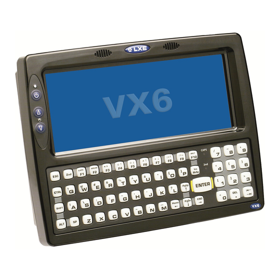
Chapter 1: Introduction The VX6 is a rugged vehicle-mounted computer with a Microsoft® Windows® CE 5 operating system. The VX6 and its Quick Mount Smart Dock are designed to be mounted in a vehicle with either a RAM mount or U bracket system. A power cable is provided with each VX6. -
Page 10: Preparing The Powered Vehicle Mounted Cradle For Use
Can be easily accessed by a user seated in the driver's seat while the vehicle is not in operation. Quick Start The following list outlines, in a general way, the process to follow when preparing the VX6 powered vehicle mounted cradle for use. Refer to the following sections in this document for more details. -
Page 11: Maintenance - Vehicle Mounted Devices
Use a clean soft cloth to wipe any dirt, moisture or grease from the VX6, connectors, cables or the vehicle mounting hardware. Do not use any liquid to clean the VX6, or connectors. Spray or dampen the cleaning cloth with the cleaning liquid. If possible,... -
Page 13: Chapter 2: Install U Mounting Brackets
Equipment Needed: Phillips No. 1 screwdriver and a Torque wrench capable of measuring to 50 inch pounds (5.64±.56 N/m). Note: Torquing tool is not supplied by Honeywell. Bolts, washers, and wrench needed when attaching the bottom mounting bracket to the vehicle are not supplied by Honeywell. -
Page 14: U-Bracket Mount System
Components Bottom Mounting Bracket This bracket is mounted to the vehicle. The VX6 can be mounted to the bottom mounting bracket. Additionally, the UPS battery pack may be mounted to the bottom mounting bracket. If the optional UPS battery pack is to be mounted to the bottom bracket, use the following parts included with the UPS battery pack: 1”... -
Page 15: Back Bracket Assembly
Back Bracket Assembly Note: Rear Bracket may have a different appearance than shown however hardware and mounting instructions are the same. Back Bracket Hardware: 1/4 flat washer (8 each) 1/4 locking washer (8 each) 1/4 flat washer (8 each) -
Page 16: Procedure
Procedure Mounting Positions The VX6 viewing angle can be adjusted through a wide range to provide the best viewing angle. Torque Measurement You will need a torquing tool capable of torquing to 50 inch pounds (5.64±.56 N/m). Torque all screws and bolts according to the following table: For these screws and bolts…... -
Page 17: Step 1 - Mount Bottom Mounting Bracket To Vehicle
1/4 bolts and washers not included. It is recommended to use lock washers and flat washers on the fasteners. IMPORTANT: Mount to the most rigid surface available. After the bottom bracket has been attached to a rigid surface, you are ready to assemble the VX6 bracket configuration. Mounting Dimensions 1. -
Page 18: Step 2 - Attach Back Bracket To Vx6
2. Place the VX6 face down on a stable surface. 3. Align the rear bracket with the holes on the back of the VX6. Attach with four 1/4- 20x5/8 bolts, using one flat washer and one locking washer per bolt. Place the locking washer on the bolt before the flat washer. -
Page 19: Step 3 - Attach Assembly To Bottom Mount Bracket
Important: Do not torque bolts until all bolts are in place and viewing angle is adjusted. 3. Loosen the hex bolts on both sides to adjust the viewing angle of the mounted VX6. 4. Torque the hex bolts to 50±5 in lb (5.64±.56 N m). -
Page 20: Step 4 - Attach Ups Battery Pack
Step 4 - Attach UPS Battery Pack 1. If using a UPS battery pack, the battery pack can be mounted to the bottom mounting bracket. Place a locking washer and then a flat washer on a 1/4-20x2 bolt. Thread the bolt through the UPS Battery Pack, then through the 1” aluminum spacer and into the mounting bracket. -
Page 21: Completed Assembly
Completed Assembly... - Page 22 2-10...
-
Page 23: Chapter 3: Install Ram Mounting Brackets
Equipment Needed: Phillips No. 1 screwdriver and a Torque wrench capable of measuring to 50 inch pounds (5.64±.56 N/m). Note: Torquing tool is not supplied by Honeywell. Bolts, washers, and wrench needed when attaching the bottom mounting bracket to the vehicle are not supplied by Honeywell. -
Page 24: Ram Ball Mount System
RAM Ball Mount System Components The RAM mounting assembly consists of the following parts: 1. VX6 RAM ball bracket 2. RAM arm, size D 3. RAM ball base- or - RAM clamp mount RAM Clamp Mount includes: Upper Clamp Piece with Ball... -
Page 25: Procedure
1. Determine the position for mounting the RAM ball base. Be sure to position the RAM bracket to allow access to the switches and ports on the bottom of the VX6. 2. Attach the RAM ball base to the vehicle mounting surface using four 1/4 bolts (or equivalent) fasteners. -
Page 26: Mounting Dimensions
Mounting Dimensions Note: Drill and tap holes for 1/4 bolts. (Not To Scale) -
Page 27: Step 1B - Mount Vehicle Ram Clamp Mount
(not included). Be sure to position the RAM clamp mount to allow access to the switches and ports on the bottom of the VX6. 2. Position the upper clamp piece with ball (A) on the beam. Place the bolts (B) through the holes in the upper clamp piece. -
Page 28: Mounting Dimensions
Mounting Dimensions A. 2.56” (65.02 mm) B. 1.84” (46.74 mm) Varies depending on bolt length (Not To Scale) -
Page 29: Step 2 - Attach Ram Ball To The Vx6
1. Turn the VX6 off before attaching the RAM mount ball. 2. Place the VX6 face down on a stable surface. 3. Position the RAM ball bracket on the rear of the VX6, aligning the curved edge on the RAM mount bracket with the curved edge on the VX6. -
Page 30: Step 3 - Attach Vx6 Assembly To Ram Mount
1. Slip the RAM arm over the ball on the vehicle RAM ball bracket. 2. Insert the ball of the RAM mount bracket into the RAM arm. 3. Adjust the VX6 to the desired position and tighten the knob on the RAM arm using the supplied RAM wrench. Note:... -
Page 31: Completed Assembly
Completed Assembly Note: RAM ball base shown. -
Page 32: Ram Bracket Mount System
RAM Bracket Mount System Components The RAM mounting assembly consists of the following parts: 1. VX6 RAM ball bracket 2. RAM arm, size D 3. RAM ball base - or - RAM clamp mount RAM Clamp Mount includes: Upper Clamp Piece with Ball... -
Page 33: Procedure
1. Determine the position for mounting the RAM ball base. Be sure to position the RAM bracket to allow access to the switches and ports on the bottom of the VX6. 2. Attach the RAM ball base to the vehicle mounting surface using four 1/4 bolts (or equivalent) fasteners. -
Page 34: Mounting Dimensions
Mounting Dimensions Note: Drill and tap holes for 1/4 bolts. (Not To Scale) 3-12... -
Page 35: Step 1B - Mount Vehicle Ram Clamp Mount
(not included). Be sure to position the RAM clamp mount to allow access to the switches and ports on the bottom of the VX6. 2. Position the upper clamp piece with ball (A) on the beam. Place the bolts (B) through the holes in the upper clamp piece. -
Page 36: Mounting Dimensions
Mounting Dimensions A. 2.56” (65.02 mm) B. 1.84” (46.74 mm) Varies depending on bolt length (Not To Scale) 3-14... -
Page 37: Step 2 - Attach Ram Mount Ball To The Vx6
1. Turn the VX6 off before attaching the RAM mount ball. 2. Place the VX6 face down on a stable surface. 3. Position the RAM ball bracket on the rear of the VX6, aligning the curved edge on the RAM mount bracket with the curved edge on the VX6. -
Page 38: Step 3 - Attach Vx6 Assembly To Ram Mount
1. Slip the RAM arm over the ball on the vehicle RAM ball bracket. 2. Insert the ball of the RAM mount bracket into the RAM arm. 3. Adjust the VX6 to the desired position and tighten the knob on the RAM arm using the supplied RAM wrench. Note: RAM ball base shown. -
Page 39: Completed Assembly
Completed Assembly Note: RAM ball base shown. 3-17... - Page 40 3-18...
-
Page 41: Chapter 4: Connect Cables
Chapter 4: Connect Cables There are many cables available for the VX6. This section deals with those cables that are a part of the installation process, such as: Various data and communication cables are available for the VX6. -
Page 42: Vehicle 12-80 Vdc Power Connection
8. Green Note: Correct electrical polarity is required for safe and proper installation. Connecting the cable to the VX6 with the polarity reversed will cause the VX6 fuse to be blown. See the following figure titled “Vehicle Connection Wiring Color Codes”... -
Page 43: Connect Vehicle 12-80Vdc Connection
Connect Vehicle 12-80VDC Connection 1. The VX6 must be turned off and the power cable must be UNPLUGGED from the VX6. 2. While observing the fuse requirements specified above, connect the power cable as close as possible to the actual battery terminals of the vehicle. -
Page 44: Connect Vx6 Without A Ups Battery Pack
“Connect Vehicle 12-80VDC Connection”. 2. Connect the power cable to the VX6 by aligning the water-tight connector pins to the power connector on the bottom of the VX6; push down on the water-tight connector and twist it to fasten securely. -
Page 45: Connect Vx6 To An Integrated Mount Ups Battery Pack
3. Connect the output cable (labeled “To Computer”) from the UPS battery pack to the power connector on the bottom of the VX6 by aligning the water-tight connector to the power connector; push down on the water-tight connector and twist it to fasten securely. -
Page 46: Connect Vx6 To A Remotely Mounted Ups Battery Pack
6. Connect the output end of the extension cable to the power connector on the bottom of the VX6 by aligning the water- tight connector to the power connector; push down on the water-tight connector and twist it to fasten securely. -
Page 47: Power Adapter Cable
Push down on the water-tight connector and twist it to fasten securely. 3. Connect the larger end of the Power Cable directly to the VX6 or to a UPS battery pack, as desired. Please refer to... -
Page 48: External Power Supply, Optional
3. Plug the cordset into appropriate, grounded, electrical supply receptacle (AC mains). 4. Connect the watertight connector end to the VX6 Power Connector by aligning the connector pins to the power connector; push down on the watertight connector and twist it to fasten securely. -
Page 49: Strain Relief Cable Clamps
Strain Relief Cable Clamps Equipment Required: Phillips screwdriver (not supplied by Honeywell) There are strain relief cable clamps secured to the back of the VX6. Use the strain relief clamps to secure audio, power, and I/O cables attached to the VX6. -
Page 50: Uninterruptible Power Supply Battery Pack
(such as when vehicle batteries are swapped). Fully charged, the UPS battery pack powers the VX6 for a minimum of 15 minutes at 25º C (77º F) ambient temperature. The Power Status LED on the VX6 indicates the UPS battery pack status: Green Running on 12V –... -
Page 51: Ups Battery Pack Remote Mounting Dimensions
UPS Battery Pack Remote Mounting Dimensions 1. 11.00” / 279.40 mm 2. 10.23” / 259.80 mm 3. 0.38” / 9.65 mm 4. 1.39” / 35.31 mm 5. 3.04” / 77.22 mm 6. 0.30” / 7.62 mm 4-11... -
Page 52: Fuse Replacement For The Vx6
1. Turn the VX6 off and disconnect the power cable from the VX6. 2. While holding the VX6 over a level surface, push the fuse cover in and twist it one quarter turn counterclockwise. A flat head screwdriver may be used to twist the fuse cover. -
Page 53: Connect Antenna
(installed when manufactured) Note: VX6’s are equipped with a radio and require an antenna. Some VX6’s may be equipped with a dual antenna option. For these VX6’s, an external antenna must be connected to each antenna connector. Connect External Antenna If the internal antenna option was selected, there are no external antenna connectors on the VX6. -
Page 54: Internal Antenna
Internal Antenna If the internal antenna option is ordered, an antenna is mounted on the inside of the user access panel cover (located on top of the VX6). The internal antenna assembly has two antenna cables. Attach the antenna cables to the radio card. -
Page 55: Remote Antenna Installation Kit
Tools are not included. The remote antenna base is mounted on the top of a forklift, truck or other vehicle and cabled to the VX6 inside the vehicle. The cable is available in different lengths and with a straight or right angle adapter on the end. -
Page 56: Components And Mounting Diagram
Components and Mounting Diagram 1. Nut 2. Washer 3. Washer 4. Mounting Plate 5. To Antenna 6. To VX6 Antenna Connector 7. Antenna Typical Installation 1. Antenna 2. Mounting Plate 3. Vehicle Safety Cage 4. Coaxial Cable 5. Vehicle Mounted VX6... -
Page 57: Remote Antenna Mounting Instruction
If the VX6 requires two antennas, they must be mounted at least 12 inches (304.8mm) apart. 2. Attach the female connector of the coaxial cable to the antenna connector on the vehicle mounted VX6. 3. Insert the male connector on the coaxial cable though the hole in the mounting plate. - Page 58 4-18...
-
Page 59: Chapter 5: Technical Assistance
Limited Warranty Honeywell International Inc. ("HII") warrants its products to be free from defects in materials and workmanship and to conform to HII’s published specifications applicable to the products purchased at the time of shipment. This warranty does not cover any HII product which is (i) improperly installed or used;... - Page 60 The duration of the limited warranty for the VX6 external UPS battery is 1 year. The duration of the limited warranty for the VX6 AC power supply and cables is 1 year. The duration of the limited warranty for the VX6 DC-DC Converter is 1 year.
- Page 62 Honeywell Scanning & Mobility 9680 Old Bailes Road Fort Mill, SC 29707 www.honeywellaidc.com E-EQ-VX6OGWW Rev E 10/12...