Table of Contents
Advertisement
Quick Links
TTWS Series
THERMAL WEAPON SIGHTS
OPERATOR'S MANUAL (TTWS Series) REVISION 4 – APRIL, 2014
o p e r a t o r ' s m a n u a l
Important Export Restrictions! Commodities, products,
technologies and services contained in this manual are
subject to one or more of the export control laws and
regulations of the U.S. Government and they fall under the
control jurisdiction of either the US Department of State or the
US BIS-Department of Commerce. It is unlawful and strictly
prohibited to export, or attempt to export or otherwise transfer
or sell any hardware or technical data or furnish any service to
any foreign person, whether abroad or in the United States, for
which a license or written approval of the U.S. Government is
required, without first obtaining the required license or written
approval from the Department of the U.S. Government having
jurisdiction. Diversion contrary to U.S. law is prohibited.
Advertisement
Table of Contents

Related Manuals for ATN TTWS Series


Summary of Contents for ATN TTWS Series
- Page 1 TTWS Series THERMAL WEAPON SIGHTS OPERATOR’S MANUAL (TTWS Series) REVISION 4 – APRIL, 2014 o p e r a t o r ’ s m a n u a l Important Export Restrictions! Commodities, products, technologies and services contained in this manual are subject to one or more of the export control laws and regulations of the U.S.
- Page 2 Manual (TTWS Series) Revision 4 – April, 2014 The information in this manual furnished for information use only, is subject to change without notice, is not to be construed as a commitment by ATN Corp. ATN Corp. assumes no responsibility or liability for any errors or inaccuracies that may appear in this book.
- Page 3 STUDY CAREFULLY THIS MANUAL BEFORE TURNING ON AND OPERATING THIS PRODUCT. CAUTIONS The TTWS Series Thermal Digital Riflescopes are precision electro-optical instruments and requires careful handling. To pro- vide safe use of the systems the following instructions should be observed: •...
- Page 4 (such as the sun or a welding arc). If you do, you will damage the scope. WARNING Operating TTWS Series outside of its specified operating tempera- ture range or voltage range can cause permanent damage and will void the warranty.
- Page 5 Observe battery manufacturer’s guidelines for safe handling and proper disposal of batteries. EQUIPMENT LIMITATIONS • The TTWS Series detector spectral band (7 to 14 mkm) pro- vides a better penetration through smoke, smog, dust, water vapor etc. • Infrared radiation does not travel through glass and therefore the scope does not sense objects if they are behind a glass window.
-
Page 6: Table Of Contents
TABLE OF CONTENTS CHAPTER 1. INTRODUCTION ....1-1 1.1. General Information ....1-2 1.1.1. - Page 7 3.2.6. Zoom ......3-7 3.2.7. Color Modes ..... . . 3-8 3.2.8.
- Page 8 HOW TO USE THIS MANUAL • Usage You must familiarize yourself with the entire manual before operat- ing the equipment. Read and follow all warning notices. • Manual Overview The table of contents includes the paragraph number, paragraph title, and page number. An index provides additional references to the subject contents.
-
Page 9: Chapter 1. Introduction
CHAPTER 1 INTRODUCTION... -
Page 10: General Information
1.1.1. SCOPE This manual contains instructions for use in operating and main- taining the TTWS Series Thermal Digital Riflescopes. Throughout this manual, the TTWS Series will be referred to as the scope or TTWS. 1.1.2. REPORTS Reports from the user on recommendations for improvements are encouraged. - Page 11 ATN, at its option, will either repair or replace the product, and such action on the part of ATN shall be the full extent of ATN’s liability, and the Customer’s sole and exclusive remedy. This warranty does not cover a product (a) used in other than its normal and customary manner;...
- Page 12 ATN shall not, in any event, be liable for special, indirect, incidental, or consequential damages, including, but not limited to, lost income, lost revenue, or lost profit, whether such damages were foreseeable or not at the time of purchase, and whether or not such damages arise out of a breach of warranty, a breach of agreement, negligence, strict liability or any other theory of liability.
-
Page 13: Description And Data
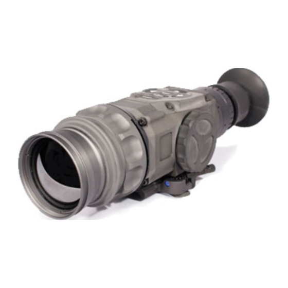
1.2. DESCRIPTION AND DATA 1.2.1. DESCRIPTION a. Purpose The TTWS Series Thermal Digital Riflescopes combines the ergo- nomic features of a handheld and the convenience of weapon mounting. Based on the proven 324x256 or 336x256 or 640x512 microbolometer core, the TTWS is an ideal product for force pro-... - Page 14 • Four reticle colors: red, green, white, black • Ten-step brightness control • Flexible battery cartridge can run on 1, 2, or 3 batteries • Batteries: (3) 3V lithium (CR123A) – AA optional (qty 4) • Battery life: 8 hours (3V)
-
Page 15: Ttws Standard Components
1.2.2. TTWS STANDARD COMPONENTS The TTWS standard components are shown in Figure 1.3. and pre- sented in Table 1.1. FIGURE 1.3. TTWS STANDARD COMPONENTS TABLE 1.1. TTWS STANDARD COMPONENTS ITEM DESCRIPTION Scope The thermal imaging scope. Quick Release Mount Used to mount scope to weapon. Hard Storage Case A protective case used for shipping/storing TTWS and accessories. - Page 18 1-10...
-
Page 19: Mechanical Function
1.2.4. MECHANICAL FUNCTION The mechanical adjustments of the TTWS sights allow for physi- cal differences between individual operators using the system. The scope functions include the Keypad, Output Connector, Eyepiece Diopter Adjustment Ring, Focusing Ring, Battery Module, Accessory Rail, and Weapon Mount. The controls are identified in Figure 1.4. FOCUSING KEYPAD DIOPTER... -
Page 20: Electrical Function
from infrared detector is passed to electronics for image process- ing. The signal processing circuitry translates the infrared detector data into an image that can be viewed on the built-in OLED display. The image is observed through an eyepiece by operator. 1.2.6. -
Page 21: Chapter 2. Assembly And Preparation
CHAPTER 2 ASSEMBLY AND PREPARATION... -
Page 22: Preparation
2.1. PREPARATION 2.1.1. PREPARATION FOR USE This chapter contains the information necessary to prepare the scope for operation. This includes unpacking, examination for damage, and batteries installation. a. Unpacking The following steps must be accomplished prior to each mission where the sight is used. 1. -
Page 23: Examination For Operation
3. Replace battery module into the housing. Screw clockwise until finger tight. FIGURE 2.1. LOADING BATTERY MODULE FIGURE 2.2. INSTALL BATTERY MODULE 2.1.2. EXAMINATION FOR OPERATION Before getting started, make sure to follow these steps: 1. Push Power button on the scope. 2. -
Page 24: Assembly
2.2. ASSEMBLY 2.2.1. REMOVE/INSTALLATION OF QUICK RELEASE MOUNT (QRM) ARMS #17 Lever Quick Release Mount (QRM) is used for fast installation/removing the TTWS on MIL-STD-1913/Picatinny rail. FIGURE 2.3. LEVER QUICK RELEASE MOUNT FIGURE 2.4. QUICK RELEASE MOUNT ADJUSTMENT 1. To open the QRM, slide the cam latch forward (arrow A). -
Page 25: Video Output
2. Place the scope onto rail. Be sure to engage the recoil lug into the groove on the top mounting surface of the rifle. 3. Turn the cam backwards pushing the latch to close the mount (arrow B). 4. The QRM may be adjusted to eliminate excessive play when mounted on the rail by using the adjustment knob on the lever to release the lever from the adjuster. - Page 26 2. BNC Plug to RCA Jack Adapter FIGURE 2.7. RCA JACK ADAPTER 3. RCA style video cables FIGURE 2.8. RCA CABLES Connection Setup: 1. Connect the 8 PIN-to-BNC (Figure 2.6.) cable to the sights 8 PIN port. 2. Connect the BNC Plug to RCA Jack Adapter (Figure 2.7.), to the 8 PIN-to-BNC cable.
- Page 27 be viewed through the TTWS eyepiece and the monitor at the same time. FIGURE 2.9. OPERATION SWITCHBOARD The user, while looking through the TTWS eyepiece, will be able to tell if video is being displayed on the monitor, because the icon will be visible in the bottom left corner of the eyepiece.
- Page 28 FIGURE 2.10. CAMERA ICON ON SCREEN How to download images to PC. 1. Install ATN Interface Software on your PC. 2. With TTWS On plug in image capture cable to TTWS and PC. 3. Open “ATN Scope Interface” software. 4. Click on menu named: Settings.
-
Page 29: Chapter 3. Operation
CHAPTER 3 OPERATION... -
Page 30: General Information
3.1. GENERAL INFORMATION 3.1.1. GENERAL This section contains instructions for operation of TTWS. The func- tion of controls and indicators is explained. CAUTION The TTWS scope is a precision electron-optical instru- ment and must be handled carefully at all times. 3.1.2. -
Page 31: Operating Procedure
TABLE 3.1. CONTROLS AND INDICATION CONTROLS ITEMS FUNCTIONS AND INDICATORS Controls scope power. To turn the unit on POWER Button and off press the button ENTER Button Used to select or enter selection Digital Zoom, Reticle Color, Elevation Up Up Arrow Adjustment Brightness, Calibration, Elevation Down Down Arrow... -
Page 32: Focusing
FIGURE 3.2. SWITCHBOARD OF TTWS 3.2.2. FOCUSING To focus the scope you need to adjust the diopter first. The scope has an adjustable eyepiece with a range of +2 to -6 diopter. Simply turn the diopter clockwise until it stops. Then concentrate on any object and slowly turn the diopter back counter clockwise until the grain in the image is sharp. -
Page 33: Ism - Interactive Symbology Menu
NOTE The front lens should be readjusted for viewing objects at dif- ferent distances. Rotate the focusing ring clockwise for far focus, counterclockwise for near focus. 3.2.3. ISM – INTERACTIVE SYMBOLOGY MENU The TTWS features the all new ISM interactive symbology menu that enables you to easily navigate through the features and modes without having to go into a complex menu structure. -
Page 34: Polarity
RETICLE COLOR RETICLE ADJUST RETICLE WINDAGE PATTERN AND ELEVATION (5 OPTIONS) CALIBRATION (NUC) CLOSE LENS CAP BEFORE CAL FIGURE 3.5. ISM RETICLE MENU 3.2.4. POLARITY The function of polarity switching is accessible only in Black and White models. WHITE HOT BLACK HOT FIGURE 3.7. -
Page 35: Brightness
To select polarity go to ISM Main menu and push left arrow button to cycle between white hot and black hot polarities. 3.2.5. BRIGHTNESS Brightness allows you to dim or increase the brightness of the dis- play. To cycle through the BRIGHTNESS steps go to ISM Main menu and push the down arrow button for brightness adjustment. -
Page 36: Color Modes
NO ZOOM 2X ZOOM 4X ZOOM RETICLE ON TARGET RETICLE SHIFTS 2X RETICLE SHIFTS 4X FIGURE 3.8. ZOOM 3.2.7. COLOR MODES The TTWS has 10 additional color pallets to choose from in addition to the white hot and black hot polarity. Fusion, Rainbow, Globow, Ironbow1, Ironbow2, Sepia, Color1, Color2, Ice Fire, Rain. -
Page 37: Reticle Color
IMPORTANT: To Perform calibration of unit. Cover front lens with cap or hand and push Calibration button to calibrate image. Fail- ure to do this step may result in degradation of the image. Degradation may consist of unusual blurriness or ghost like spots in the image. -
Page 38: Reticle Pattern
3.2.10. RETICLE PATTERN Your scope has many reticle types/patterns to choose from: duplex, post, post with dot, open cross hair, standard crosshair. To select reticle type go to ISM Reticle menu and push Left arrow button to cycle through the reticle patterns. BALLISTIC DUPLEX CROSSHAIR... - Page 39 RETICLE ADJUSTMENT ICON FIGURE 3.13 b) This Menu will now appear (depicted in Figure 3.14). FIGURE 3.14 c) The Right/Left and Up/Down arrows may now be pressed to move the Reticle position. d) The example in Figure 3.15 illustrates a new Reticle position. FIGURE 3.15 3-11...
- Page 40 e) When the Reticle has been adjusted to the desired position, press the Center button. This “SV?” Icon will appear (Figure 3.16). FIGURE 3.16 f) To insure the new Reticle position is saved, continue holding the Center button down until the “OK” icon appears (Figure 3.17). FIGURE 3.17 g) This position is now the new “Zero”.
-
Page 41: Shut Down Operations
3.2.12. SHUT DOWN OPERATIONS To finish the work, perform the following: 1. Use the POWER button to turn the scope off. 2. Hold down the POWER button (3 seconds) until the icon goes away then release the POWER button. This is a safety so the system is not accidentally turned off. - Page 42 3-14...
-
Page 43: Chapter 4. Maintenance Instructions
CHAPTER 4 MAINTENANCE INSTRUCTIONS... -
Page 44: Preventive Maintenance Checks And Services (Pmcs)
4.1. PREVENTIVE MAINTENANCE CHECKS AND SERVICES (PMCS) 4.1.1. PURPOSE OF PMCS PMCS is performed daily when in use to be sure that the sight is ready at all times. Procedures listed in Table 4.1. are a systematic inspection of TTWS that will enable you to discover defects that might cause the sight to fail on a mission. - Page 45 SEQ. ITEM TO CHECKING NOT FULLY MISSION CHECK PROCEDURE CAPABLE IF: Check to ensure: — the focus ring cannot be Focus ring able to moved along the sight body; move along sight Focus Ring — there is free rotation of body.
-
Page 46: Troubleshooting
4.2. TROUBLESHOOTING 4.2.1. GENERAL This section contains information for locating and removal most of the TTWS operating troubles which may occur. Each malfunction for an individual component or assembly is followed by a list of tests or inspections that will help determine probable causes and cor- rective action to take. -
Page 47: Maintenance Procedures
4.3. MAINTENANCE PROCEDURES 4.3.1. SCOPE MAINTENANCE The TTWS maintenance consists of external inspection of its com- ponents for serviceability, cleaning and installation of the stan- dard and optional accessories. Maintenance instructions covered elsewhere in this manual (PMCS, troubleshooting, etc.) are not repeated in this section. -
Page 48: Preparing For Extended Storage
4.3.3. PREPARING FOR EXTENDED STORAGE To prepare the TTWS for extended storage, perform the following: 6. Check the scope for serviceability as outlined in item 4.1 of this manual. 7. Remove the batteries. 8. Clean the scope and accessories. 9. Replace all items in the case. - Page 50 For customer service and technical support, please contact American Technologies Network Corp. 1341 San Mateo Avenue, South San Francisco, CA 94080 phone: 800-910-2862, 650-989-5100; fax: 650-875-0129 www.atncorp.com ©2014 ATN Corporation...