Table of Contents
Advertisement
Quick Links
Advertisement
Table of Contents

Related Manuals for Peavey 6505 MH


Summary of Contents for Peavey 6505 MH
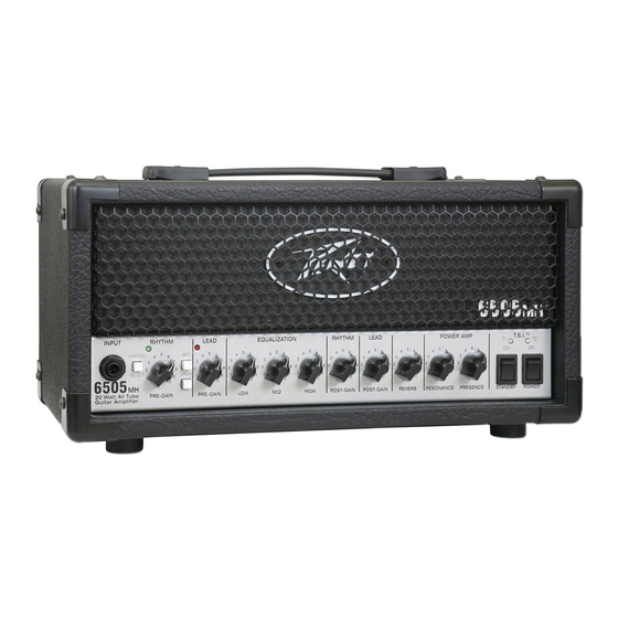
- Page 1 Peavey 6505 ® ® 20W Tube Guitar Amplifier Operating Manual www.peavey.com...
- Page 2 FCC/ICES Compliancy Statement This device complies with Part 15 of the FCC rules and Industry Canada license‐exempt RSS Standard(s). Operation is subject to the following two conditions: (1) this device may not cause harmful interference, and (2) this device must accept any interference received, that may cause undesired operation. Le présent appareil est conforme aux CNR d’lndustrie Canada applicables aux appareils radio exempts de licence. L’exploitation est autorisée aux deux conditions suivantes: (1) I’appareil ne doit pas produire de brouillage, et (2) I’utilisateur de I’appareil doit accepter tout brouillage radioélectrique subi, même si le brouillage est susceptible d’en compromettre le fonctionnement. Warning: Changes or modifications to the equipment not approved by Peavey Electronics Corp. can void the user’s authority to use the equipment. Note – This equipment has been tested and found to comply with the limits for a Class B digital device, pursuant to Part 15 of the FCC Rules. These limits are designed to provide reasonable protection against harmful interference in a residential installation. This equipment generates, uses, and can radiate radio frequency energy and, if not installed and used in accordance with the instructions, may cause harmful interference to radio communications. However, there is no guarantee that interference will not occur in a particular installation. If this equipment does cause harmful interference to radio or television reception, which can be determined by turning the equipment off and on, the user is encouraged to try and correct the interference by one or more of the following measures. Reorient or relocate the receiving antenna. Increase the separation between the equipment and receiver. Connect the equipment into an outlet on a circuit different from that to which the receiver is ...
- Page 3 Other features on the rear panel include: Effects Loop, Microphone Simulated Direct Interface (MSDI™) with XLR output and USB out, speaker defeat switch and 3 position power attenuator switch. The 6505 MH exhibits a tremendous amount of versatility in a small package; it features real tube tone, real tube power! It contains no simulations, emulations or approximations.
- Page 4 6505 MH ® Front Panel INPUT Standard 1/4” jack for connection to the output of your guitar or last pedal if using effects before the amp. CHANNEL SWITCH Allows selection of the two different channels. The“IN”position of the switch selects the ‘LEAD’ channel and the“OUT”position selects the ‘RHYTHM’...
- Page 5 * Excessive time off (more than one hour) in "STANDBY MODE" can damage OUTPUT TUBE by "poisoning the cathodes". * For an informative description of the STANDBY function, please read the Chapter 6 (Standby...For the Truth) of Hartley Peavey's White Papers included on this disc.
- Page 6 ® 6505 MH Front Panel cont. POWER switch To apply power to the unit, connect the line cord and flip the switch to the ON position. Three of the four front panel LED’s should illuminate, indicating power is being supplied. It’s best that the STANDBY switch (#13) is set to STANDBY when amp is first switched on.
- Page 7 6505 MH ® Rear Panel VOLTAGE SELECTOR SWITCH This selects between two different AC line/mains voltages. This should not normally be adjusted by the user, hence the clear plastic shield. This should already be set to the correct line/mains voltage in your country/territory.
- Page 8 MSDI™ circuit (see below), therefore is filtered for a 12” guitar speaker-like tone. MIC SIMULATED DIRECT INTERFACE - MSDI™ Peavey’s exclusive MSDI™ simulates the sound of a microphone placed approximately 8” from a 12” loudspeaker cone, allowing the user to send an accurate good quality signal to the mixing console, without any acoustic spill from other instruments on stage.
- Page 9 ‘Ring’ (Left on a Peavey footswitch): Turns the effects loop on or off. ‘Tip’ (Right on a Peavey footswitch): Turns the reverb on or off. Peavey footswitches are available with and without LEDs to indicate current settings. Please refer to www. peavey.com or customer services for more information and product codes.
- Page 10 ® 6505 MH All-Tube Guitar Amplifier SPECIFICATIONS Rated Power: 20 W(rms) into 8 or 16Ω Special 2-button unit with LED *Features and specifications indicators (#00579720) subject to change without notice. One footswitch for channel selection Power Consumption: (Domestic) 90 and boost functions.
- Page 11 What Peavey Will Do We will repair or replace (at Peavey’s discretion) products covered by Warranty at no charge for labor or materials. If the product or component must be shipped to Peavey for Warranty service, the consumer must pay initial shipping charges. If the repairs are covered by Warranty, Peavey will pay the return shipping charges.
- Page 12 ❒ Other 3. http://__________________________________________ 15. In your opinion, what could Peavey do to improve its products and/or service? Please use the space below to tell us your answer. Logo referenced in Directive 2002/96/EC Annex IV (OJ(L)37/38,13.02.03 and defined in EN 50419: 2005 Thank you for taking the time to fill out our survey! Don’t forget to fold and tape...