Philips PET716 Service Manual
Philips pet716 portable dvd player service manual
Hide thumbs
Also See for PET716:
- User manual (18 pages) ,
- Quick start manual (1 page) ,
- User manual (18 pages)
Advertisement
Quick Links
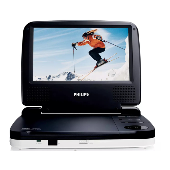
DVD Portable Player
Service Manual
TABLE OF CONTENTS
Technical Specification & Service Tips......................... 1
Safety Instructions..................................................... 2
Instruction for Use...................................................... 3
Mechanical Instructions.............................................. 4
Troubleshooting .........................................................5
Overall Block Diagram................................................. 6
Electrical Diagram...................................................... 7
Service Part List.......................................................... 8
Revision List............................................................. 9
©Copyright 2005 Philips Consumer Electronics B.V. Eindhoven, The Netherlands
All rights reserved. No part of this publication may by reproduced, stored in a
retrieval system or transmitted, in any form or by any means, electronics,
mechanical, photocopying, or otherwise without the prior permission of Philips
Version 1.2
PET716
All version
Chapter
3141 785 31862
Advertisement

Related Manuals for Philips PET716


Summary of Contents for Philips PET716
-
Page 1: Table Of Contents
All rights reserved. No part of this publication may by reproduced, stored in a retrieval system or transmitted, in any form or by any means, electronics, mechanical, photocopying, or otherwise without the prior permission of Philips 3141 785 31862 Version 1.2... -
Page 2: Technical Specification
1.0 TECHNICAL SPECIFICATION General Playback disc type: DVD, Picture-CD, SVCD, Video CD, MP3- CD, CD-R/CD-RW, WMA-CD, DVD-R, DVD- Dimensions (W x H x D): 210 x 178 x 39mm RW, DVD+R, DVD+RW Bear Unit Weight: 719.3g +/- 5% Power supply: Input: 100-240V AC, 50/60Hz Video Playback Format: DVD / VCD / JPEG... - Page 3 For the best performance of your DVD Portable. Check www.philips.com/support for latest software upgrades available. A) By CD-ROM Download the “PHILIPS.BIN” file from the Philips support site Unzip the file and then burn it into a CD-ROM to make a disc for upgrade CD-ROM disc name must be “PHILIPS”...
- Page 4 2.0 SAFTETY INSTRUCTIONS WAARSCHUWING WARNING Alle IC’s en vele andere halfgeleiders zijn All ICs and many other semi-conductors are gevoelig voor electrostatische ontladingen susceptible to electrostatic discharges (ESD). (ESD). Careless handling during repair can reduce life Onzorgvuldig behandelen tijdens reparatie kan drastically.
- Page 5 2.1 ESD PROTECTION When the power supply is being turned on, you may not remove this laser cautions label. If it removes, radiation of laser may be received. PREPARATION OF SERVICING Pickup Head consists of a laser diode that is very susceptible to external static electrocity. Although it operates properly after replacement, if it was subject to electrostatic discharge during replacement, its life might be shortened.
- Page 6 SAFTY NOTICE SAFTY PRECAUTIONS LEAKAGE CURRENT CHECK Plug the AC line cord directly into a 120V AC outlet (do Measure the AC voltage across the 1500 resistor. not use an isolation transformer for this check). Use an The test must be conducted with the AC switch on and AC voltmeter, having 5000 per volt or more sensitivity.
-
Page 7: Instruction For Use
3.0 INSTRUCTION FOR USE... -
Page 8: Mechanical Instructions
4.0 MECHANICAL INSTRUCTION Disassembly Procedure 1. Remove 7pcs of screws on the side of bottom cabinet. 2. Open the bottom cabinet, up-plug all the wire connecter from main board (The wire connecter are for : DVD loder, battery board and TFT driver board, Key board and speaker) Remove all the screws on the main board, then take the main board from bottom cabinet. - Page 9 4.0 MECHANICAL INSTRUCTION 7. To remove the hinge, remove the screws on the hinge. 8. To remove the TFT, de-soldering the wire connected between TFT and TFT board first. (Please note the wire location as shown in picture during re-assembly) And up pulg wire connecter from TFT board.
-
Page 10: Troubleshooting
5.0 TROUBLESHOOTING SYMPTOM: BATTERY NO POWER BATTERY CAN'T Power ON Start Check charging Check adaptor Check Battery capacity? SET OK? function OK? power-ON OK? Check the Power-ON No Defect, return button and cable OK? set to Customer Replace Button or Replace Main Board Cable... - Page 11 5.0 TROUBLESHOOTING SYMPTOM: NO IMAGE / NO SOUND SYMPTOM: NO IMAGE OUTPUT ( THE PANEL SHOW BLUE PICTURE) Start Check DVD Drive work? Replace DVD Drive Check the external AV NOTE: AV Cable TYPE from outside to note Cable TYPE Exchange AV cable Inside L-Audio, R-Audio, Video, Ground connection is OK?
- Page 12 5.0 TROUBLESHOOTING SYMPTOM: THE DVD DRIVE DOES NOT WORK SYMPTOM: THE DVD DRIVE DOESN'T WORK Start Check DVD-Loader Cable Reinsertion connection OK? Check the DVD-Loader Replace DVD- Loader Replace main board...
- Page 13 5.0 TROUBLESHOOTING SYMPTOM: ADAPTOR CANNOT POWER ON Adaptor can not Power ON Start Check Adaptor OK? Change adaptor SET OK? Check the Power-ON Return set to Replace Main Board button and cable OK? Customer Replace Button or Cable...
- Page 14 5.0 TROUBLESHOOTING SYMPTOM: REMOTE CONTROL CANNOT WORK SYMPTOM: THE REMOTE CONTROL CAN NOT WORK Start Check CABLE form bottom board to top board Cable Reinsertion connection OK? Check TOP-board OK? Replace IR receiver Replace top board Replace main board Return to custormer...
- Page 15 5.0 TROUBLESHOOTING SYMPTOM: NO SOUND FROM HEADPHONE...
- Page 16 5.0 TROUBLESHOOTING SYMPTOM: LED DISPLAY FAILURE SYMPTOM: LED Display Fail Start Check CABLE form Main board to top board Cable Reinsertion connection OK? Check TOP-board OK? Replace LED Replace top board Replace main board Return to custormer...
- Page 17 5.0 TROUBLESHOOTING SYMPTOM: KEY & BOTTON FAILURE SYMPTOM: Key & Botton Fail Start Check CABLE form board to Cable Reinsertion board connection OK? Check KEY board OK? Replace KEY board Replace main board Return to custormer...
- Page 18 6.0 BLOCK DIAGRAM...
- Page 19 7.0 Electrical Diagram VCC1 VCC1 R222 R224 R226 R228 R230 R232 R234 R236 R240 R242 OPEN OPEN 100K 100K 100K COLOR RGB-AMP SUBB BRIGHT CONTRAST PICTURE R305 BOUT GOUT ROUT C229 R306 10K C219 C230 R223 C220 C225 C228 100K 100K C221 R227...
-
Page 20: Electrical Diagram
7.0 Electrical Diagram CHECK CHECK B1184 1.25A R138 10UF 470K 10UF\25v SI2313 2412 7805 150K IC11 2412 C945 S-8241ABJ R137 100K 470K OPEN 100K 0.1UF 0.47UF R135 10UF 10UF 100K 2312 OPEN P0.0 XOUT P0.1 P1.2 P0.2 LM358 S3C9444 IC3A 0.1UF 0.1UF LM358... - Page 21 SS14 AVCC OUT2 0.1UF DC JACK(+9V~+12V 100uF/16V 0.1uF EC10 47uF/16V 0.1uF 100uF/16V VCC3 POWER_SW 1.5K LED2 LED3.0 Batter 7.0 Electrical Diagram POWER LED POWER ON/OFF SWITCH DESIGN APPROVED Title POWER Size Document Number PET716 DVD MAIN BOARD Date: 2005.12.12 Sheet...
- Page 22 CTK1 VINSL+ TRSO VINTK protection OPU V1P4 BIAS 150pF CB32 STBY FOSO STBY VINFC 150pF 0.1uF BA5954 CB33 CE11 DESIGN APPROVED 0.1uF 47uF/16v LDO2 LDO_DVD LDO1 LDO_CD Title PORTABLE1389HD_FORYOU-DM520ANR Size Document Number Custom PET716 DVD MAIN BOARD Date: 2005.12.12 Sheet...
- Page 23 0.1uF DV33 WP/ACC 4.7K 4.7K BYTE PCE# CB37 PRD# 24C01/CAT24C021 GND1 DV33 PWR# 0.1uF GND2 I2C ADDR = 0XA0 RESET MX29LV160 TSOP 48 pin Title 1,2,4,5 SDRAM&FLASH Size Document Number 7.0 Electrical Diagram PET716 DVD MAIN BOARD Date: Sheet 2005.12.12...
- Page 24 220uF/16V BC14 BC15 L_HP_IN EC17 APA2822 0.1uF 0.1uF 100uF/16V 200K A_MUTE 4.7R 4.7R AUD_GND AUD_GND 7.0 Electrical Diagram 3904(NC) AUD_GND AUD_GND AUD_GND SP_R AUD_GND SP_L Title A/V IN/OUT 4PIN/1.25mm(TO SPEAKER) Size Document Number PET716 DVD MAIN BOARD Date: 2005.12.12 Sheet...
- Page 25 IO-2 IO-1 IO-0 MENU RIGHT LEFT IO-6 PLAY/PAUSE DOWN BAND MUTE IO-5 STOP NEXT SOURCE AUTO PROG/RAD PROG IO-4 WIDE SOURCE AUTO PROG/RAD PROG IO-3 7.0 Electrical Diagram Title Size Document Number PET716 KEY BOARD Date: Sheet...
-
Page 26: Service Part List
KEY PCBA ASSY PET716LP PET716/58 996510009822 (for S/N: GS2Bxxxxxxxx or above / VN1Cxxxxxxxx or above) PET716S/05 996510009822 KEY PCBA ASSY PET716LP TFT DRIVER PCB ASSY PET716 996510002371 (for S/N: GS1Axxxxxxxx / below PET716/05 VN1Cxxxxxxxx) PET716/12 TFT DRIVER PCB ASSY PET716LP PET716/58... - Page 27 7'' LCD PANEL ASSY LG E2 PET716/58 996510009823 (for S/N: GS2Bxxxxxxxx or above / VN1Cxxxxxxxx or above) PET716S/05 996510009823 7'' LCD PANEL ASSY LG E2 PET716/05 PET716/12 996510002361 DVD LOADER PET716 PET716/58 PET716S/05 996510007686 DVD LOADER PET716S PET716/05 PET716/12 996510002384 FFC 24P PET716/58 PET716S/05...
- Page 28 DISPLAY FRAME & SPEAKER PET716/12 996510004279 PET716 PET716/58 DISPLAY FRAME & SPEAKER PET716S/05 996510009928 PET716S PET716/05 PET716/12 996510004277 DVD TOP CABINET PET716 PET716/58 PET716S/05 996510009922 DVD TOP CABINET PET716S PET716/05 PET716/12 996510004278 CD DOOR PET716 PET716/58 PET716S/05 996510009924 CD/DVD DOOR PET716S...
- Page 29 8.0 SERVICE PART LIST Mechanical Part List: Service Service Description Photo Pos. 12NC PET716S/05 996510009925 PLAY BUTTON PET716S PET716/05 PET716/12 996510004272 NAVIGATION BUTTON PET716 PET716/58 PET716S/05 996510009927 NAVIGATION BUTTON PET716S PET716/05 PET716/12 996510004273 OK BUTTON PET716 PET716/58 PET716S/05 996510009926 OK BUTTON PET716S...
- Page 30 PET716/12, PET716/58) ACADAPTOR AC/DC ADAPTER UK (for 996510005927 PET716/05) AC/DC ADAPTER UK (for 996510009921 PET716S/05) 996510004265 / AV CABLE PET716 / for PET716S AVCABLE 996510004975 996510004266 / CAR ADAPTOR PET716 / for CARADAPTOR 996510009920 PET716S 996510004267 / REMOTE CONTROL PET716 / for...
-
Page 31: Revision List
9.0 REVISION LIST Version 1.0 (3141 785 31860) • Initial release PET716/12 Version 1.1 (3141 785 31861) • Update partlist for PET716/05 & PET716/58 Version 1.2 (3141 785 31862) • Update partlist for PET716S/05...