Table of Contents
Advertisement
Advertisement
Table of Contents

Related Manuals for SAGEMCOM F@ST 4320


Summary of Contents for SAGEMCOM F@ST 4320
-
Page 1: User Manual
F@ST 4320 User Manual VER: 1.0... -
Page 2: Fcc Statement
User Manual FCC Statement This equipment has been tested and found to comply with the limits for a Class B digital device, pursuant to part 15 of the FCC rules. These limits are designed to provide reasonable protection against harmful interference in a residential installation. - Page 3 User Manual (1) This device may not cause harmful interference, and (2) This device must accept any interference received, including interference that may cause undesired operation. Caution! The manufacturer is not responsible for any radio or TV interference caused by unauthorized modifications to this equipment. Such modifications could void the user authority to operate the equipment.
- Page 4 User Manual Repairs to certified equipment should be coordinated by a representative designated by the supplier. Any repairs or alterations made by the user to this equipment, or equipment malfunctions, may give the telecommunications company cause to request the user to disconnect the equipment.
-
Page 5: Table Of Contents
User Manual Contents Safety Precautions ..................... 1 Overview ......................2 Application ..................... 2 Features ....................3 Standards Compatibility and Compliance..........4 Hardware Description and Installation ............... 5 Hardware Description ................5 3.1.1 Front Panel ................. 5 3.1.2 Rear Panel and Side Panel ............6 Hardware Installation................ -
Page 6: Safety Precautions
User Manual Safety Precautions Read the following information carefully before operating the device. Please follow the following precaution items to protect the device from risks and damage caused by fire and electric power: Use volume labels to mark the type of power. Use the power adapter that is packed within the device package. -
Page 7: Overview
User Manual Overview The xDSL Router integrates wireless LAN and USB into one unit. It is designed to provide a simple and cost-effective xDSL Internet connection for a private Ethernet and 802.11b/802.11g/802.11n wireless network. The Router combines high-speed xDSL Internet connection, Ethernet uplink, IP routing for the LAN and wireless connectivity in one package. -
Page 8: Features
User Manual 2.2 Features User-friendly GUI for web configuration Several pre-configured popular games. Just enable the game and the port settings are automatically configured. Compatible with all standard Internet applications Industry standard and interoperable DSL interface Simple web-based status page displays a snapshot of system configuration, and links to the configuration pages Downloadable flash software updates Support for up to 8 permanent virtual circuits (PVC) -
Page 9: Standards Compatibility And Compliance
User Manual 2.3 Standards Compatibility and Compliance Support application level gateway (ALG) ITU G.992.1 (G.dmt) ITU G.992.2 (G.lite) ITU G.994.1 (G.hs) ITU G.992.3 (ADSL2) ITU G.992.5 (ADSL2+) ITU G.993.1 (VDSL) ITU G993.2 (VDSL2) 3G (WCDMA, CDMA2000, TD-SCDMA) ANSI T1.413 Issue 2 IEEE 802.3 IEEE 802.3u IEEE 802.11b... -
Page 10: Hardware Description And Installation
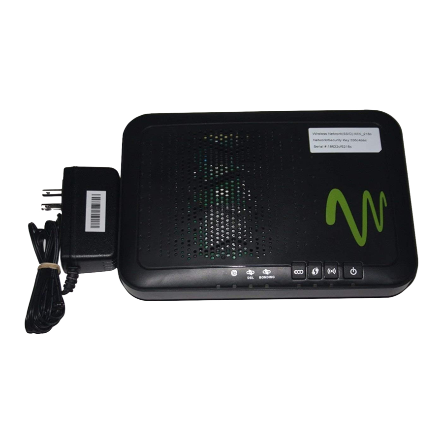
User Manual Hardware Description and Installation Note: The figures in this document are for reference only. 3.1 Hardware Description 3.1.1 Front Panel Figure 1 Front panel The following table describes the indicators on the front panel. Indicator Color Status Description The device is powered on and the device operates normally. -
Page 11: Rear Panel And Side Panel
User Manual Indicator Color Status Description Blink The DSL line is training. Device is powered off. Internet is synchronized successfully in the route mode. Green Internet Blink Internet data is being transmitted. Ethernet interface is disconnected. Authentication has failed. 3.1.2 Rear Panel and Side Panel Figure 2 Rear panel The following table describes the interfaces and the buttons. -
Page 12: Hardware Installation
User Manual Interface Description USB port, for connecting the 3G network card or other USB storage USB1/2 devices. Power Power interface, for connecting the power adapter. On/Off Power switch. WiFi WiFi switch, for enabling or disabling the WiFi function. This button is used for enabling WPS PBC mode. If WPS is enabled, press this button, and then the wireless router starts to accept the negotiation of PBC mode. - Page 13 User Manual splitter through a cable; and connect the incoming line to the Line port of the splitter. The spliiter has three ports: Line: Connect to a wall phone jack (RJ-11 jack) Modem: Connect to the Line interface of the router Phone: Connect to a telephone set Step 2 Connect the LAN port of the router to the network card of the PC through...
-
Page 14: Pc Network Configuration And Login
User Manual PC Network Configuration and Login 4.1 PC Network Configuration Each network interface on the PC should either be configured with a statically defined IP address and DNS address, or be instructed to automatically obtain an IP address using the network DHCP server. DSL router provides a DHCP server on its LAN and it is recommended to configure your LAN to automatically obtain its IP address and DNS server IP address. -
Page 15: Tcp/Ip Configuration For Windows Xp
User Manual Figure 4 IP and DNS configuration TCP/IP configuration steps for Windows XP are as follows: Step 1 Choose Start > Control Panel > Network Connections. Step 2 Right-click the Ethernet connection icon and choose Properties. Step 3 On the General tab, select the Internet Protocol (TCP/IP) component and click Properties. -
Page 16: Logging In To The Dsl Router
User Manual Step 5 Select the Obtain an IP address automatically radio button. Step 6 Select the Obtain DNS server address automatically radio button. Step 7 If you want to set the IP address and subnet mask manually, you can set the IP address and subnet mask of the computer to 192.168.1.x and 255.255.255.0 respectively. -
Page 17: Web-Based Management
User Manual Figure 5 Login page After logging in to the DSL router as a super user, you can query, configure, and modify all the settings, and diagnose the system Web-Based Management This chapter describes how to use Web-based management of the DSL router, which allows you to configure and control all of DSL router features and system parameters in a user-friendly GUI. - Page 18 User Manual VPI (Virtual Path Identifier): The virtual path between two points in an ATM network, and its valid value is from 0 to 255. VCI (Virtual Channel Identifier): The virtual channel between two points in an ATM network, ranging from 32 to 65535 (1 to 31 are reserved for known protocols).
- Page 19 User Manual PPP Username: The correct user name provided by your ISP. PPP Password: The correct password provided by your ISP. Use Static IP Address: If this function is disabled, the modem obtains an IP address assigned by an uplink equipment such as BAS, through PPPoE dial-up.
-
Page 20: Advanced Setup
User Manual 5.2 Advanced Setup 5.2.1 Layer2 Interface 5.2.1.1 ATM Interface Choose Advanced Setup > Layer2 Interface > ATM Interface . In this page, you can add or remove to configure DSL ATM Interfaces. Click Add to add ATM Interface and the following page appears. - Page 21 User Manual In this page, you can enter this PVC (VPI and VCI) value, and select DSL link type (EoA is for PPPoE, IPoE, and Bridge.), encapsulation mode, service category. VPI (Virtual Path Identifier): The virtual path between two points in an ATM network, and its valid value is from 0 to 255.
- Page 22 User Manual Select Scheduler for Queues of Equal Precedence as the Default Queue: Weighted Round Robin or Weighted Fair Queuing. Click Apply/Save to save the configuration, and return the following page: If you want to remove this Interface, please select the Remove check box and click Remove.
- Page 23 User Manual In this page, you can select scheduler for queues of equal precedence and enter the queue value. Click Apply/Save to save configuration. 5.2.1.3 ETH Interface Choose Advanced Setup > Layer2 Interface > ETH Interface, and the following page appears. In this page, you can add or remove to configure ETH WAN Interfaces.
-
Page 24: Wan Service
User Manual Click Add and the following page appears. In this page, you can select a ETH port. Click Apply/Save to save configuration. Note: If ETH Interface is selected, there are two WAN service types (PPPoE and IPoE). 5.2.2 WAN Service Choose Advanced Setup >... - Page 25 User Manual 5.2.2.1 Adding a PPPoE WAN Service This section describes the steps for adding the PPPoE WAN service. Step1 In the Wide Area Network (WAN) Service Setup page, click the Add button to display the following page. (At first, you must add a proper ATM or PTM interface for this WAN service.) Step2 In this page, you can select a ATM Interface for the WAN service.
- Page 26 User Manual Step3 In this page, select the WAN service type to be PPP over Ethernet (PPPoE). Click Next to display the following page.
- Page 27 User Manual Step4 In this page, you can modify the PPP username, PPP password, PPPoE service name and authentication method. PPP Username: The correct user name provided by your ISP. PPP Password: The correct password provided by your ISP. PPPoE Service Name: If your ISP provides it to you, please enter it. If not, do not enter any information.
- Page 28 User Manual does not stop, unless the modem is powered off and DSLAM or uplink equipment is abnormal. PPP IP extension: If you want to configure DMZ Host, you should enable it first. Use Static IPv4 Address: If this function is disabled, the modem obtains an IP address assigned by an uplink equipment such as BAS, through PPPoE dial-up.
- Page 29 User Manual Step7 In this page, you can obtain the DNS server addresses from the selected WAN interface. Click Next, and the following page appears. Step8 In this page, it displays the information about the PPPoE settngs. Click Apply/Save to save and apply the settings. 5.2.2.2 Adding a Bridge WAN service This section describes the steps for adding the Bridge WAN service.
- Page 30 User Manual or PTM interface for this WAN service.) Click the Add button to display the following page. Step2 Select the proper ATM Interface and then click Next to display the following page.
- Page 31 User Manual Step3 In this page, you can select the WAN service type, and modify the service description for this service. After finishing setting, click Next to display the following page.
-
Page 32: Wan Service
User Manual Step4 In this page, it displays the information about the bridge settngs. Click Apply/Save to save and apply the settings. You can modify the settings by clicking the Back button if necessary. 5.2.3 3G WAN Service Choose Advanced Setup > 3G Wan Service , and the following page appears. This page is used to configure 3G connection. - Page 33 User Manual In this page, you are allowed to configure the settings of the 3G USB modem. Enable USB Modem: If you want to access the Internet through the 3G network card, you must enable the USB modem. User Name: Username provided by your 3G ISP. Password: Password provided by your 3G ISP.
-
Page 34: Wireless
User Manual - DSL: If the DSL is disconnected, the 3G starts to dial. – - IP connectivity: If the system fails to ping the specified IP – address, the 3G starts to dial. After finishing setting, click the Apply/Save button to save the settings. You may also click the Auto Setting button to automatically configure the 3G connection. -
Page 35: Security
User Manual This page allows you to configure the basic features of the wireless LAN interface. Enable Wireless: Enable or disable the wireless function. Hide Access Point: if you want to hide any access point for your router, select this option, and then a station cannot obtain the SSID through the passive scanning. - Page 36 User Manual This page allows you to configure the security features of the wireless LAN interface. In this page, you can configure the network security settings by the Wi-Fi Protected Setup (WPS) method or setting the network authentication mode. WPS Setup...
-
Page 37: Management
User Manual There are 2 primary methods used in the Wi-Fi Protected Setup: PIN entry, a mandatory method of setup for all WPS certified devices. Enter STA PIN: If you select it, you need to enter the station PIN from –... -
Page 38: Access Control
User Manual 5.4.1 Access Control Passwords Choose Management > Access Control > Passwords, and the following page appears. In the page, you can modify the username and password of different users. After finishing setting, click the Apply/Save button to save and apply the settings. 5.4.2 Update Software Choose Management >... - Page 39 User Manual When software update is in progress, do not shut down the router. After software update completes, the router automatically reboots. Please make sure that the new software for updating is correct, and do not use other software to update the router. Q&A Q: Why all the indicators are off? A: Check the following:...