Table of Contents
Advertisement
Quick Links
Advertisement
Table of Contents

Related Manuals for Lennox Hearth Products 1003C


Summary of Contents for Lennox Hearth Products 1003C
-
Page 1: Installation And Operation
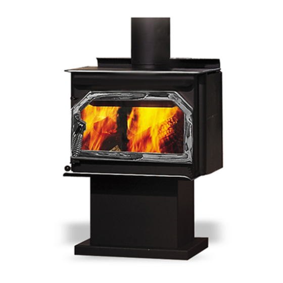
INSTALLATION AND OPERATION MANUAL EPA CERTIFIED CATALYTIC WOOD BURNING STOVE RETAIN THESE MODEL 1003C INSTRUCTIONS FOR FUTURE REFERENCE THIS APPLIANCE MUST BE INSTALLED BY A QUALIFIED INSTALLER. READ ENTIRE MANUAL THOROUGHLY BEFORE INSTALLATION. P/N 775003M, Rev. P, 11/03... -
Page 2: Important Warnings
Do not let children touch the appli- ance. Train them to stay a safe distance from the unit. the stove. Do not use grates, irons or any other method to elevate the fire. stove (or see Safety/Listing Label on page 29). -
Page 3: Table Of Contents
Safety/Listing Label...29 EPA Label ...30 Ownership Records ...31 TESTING/LISTING Model 1003C has been tested to UL Standard 1482 and ULC-S627 by OMNI-Test Laboratories Inc.; Bea- verton, Oregon; Report number #030-S-02-2. EPA CERTIFICATION This stove has been tested to rigorous emissions stan- dard, and has been certified by the Environmental Pro- tection Agency. -
Page 4: Planning Your Installation
SELECTING A LOCATION The design of your home and where you place your stove will determine its value as a source of heat. A wood stove depends primarily on air circulation (con- vection) to disperse its heat, and therefore, a central location is often best. - Page 5 2" (51 mm) to either side. The floor protection must extend completely beneath the stove and to the front, sides, and rear as indicated: USA REQUIREMENTS 16” (406 mm) min. to the front of the fuel door glass 8”...
- Page 6 C. 14.5 / 369 B. 25.5 / 648 D. 5.5 / 140 Vent Height (all installations) - The pipe should extend 12 feet above the stove top, as a minimum, to achieve a stable draft. Corner Installation E. 16 / 406 F.
- Page 7 The firebox of the masonry structure must be of ade- quate size to allow a minimum of 6” (152.4 mm) clear- ance to the sides and top of the stove and 2” (50.8 mm) clearance to the rear. All stove models must be installed on their original listed legs or base unless otherwise specified by OMNI Testing Laboratory.
-
Page 8: Manufactured (Mobile) Home Requirements
Closed MANUFACTURED (MOBILE) HOME REQUIREMENTS This stove is certified as a Room Heater, Solid Fuel Type and may be used in Manufactured Housing providing the following requirements are followed: •... -
Page 9: Installation
(4) four holes in the stove base. Mark holes, then remove the stove. Drill the (4) four holes, with a ¼” (7 mm) drill bit. Drill down through the floor protector and the manufactured (mobile) home floor. - Page 10 INSTALLATION CHIMNEY INSPECTION Existing chimneys must be inspected before installing your stove. Consult your local building department for chimney code requirements. A masonry chimney must have a code approved liner. This liner must not have bro- ken or missing pieces. Some non-code masonry chim- neys may be brought up to code by being relined.
- Page 11 Poorly functioning venting systems may create performance problems (i.e. smoking stove, poor heat output, fire goes out, window blackens, increased creosote buildup, etc.) as well as be a safety hazard. Some factors that may lead to performance problems are as follows: •...
- Page 12 INSTALLATION See Pipe Manufacturers Instructions For Installation Requirements Of Venting Components And Vent Clearances. RESIDENTIAL STANDARD Using 6” (152 mm) Diameter Single Wall Connector Pipe. Not Approved For Manufactured (Mobile) Homes. Storm Collar Roof Flashing Slip Adapter MANUFACTURED (MOBILE) HOME STANDARD Using 6”...
- Page 13 Min. Chimney Clearance to Brick & Combustibles – 2 in. (50.8mm) Min. 12 in. (304.8mm) to Combustibles Min. Chimney Clearance from Masonry to Sheet Steel Supports & Combustibles – 2 in. (50.8mm) Nonsoluble Refractory Cement Factory Built Chimney Length Chimney Length Flush with In- side of Flue Air Space –...
- Page 14 The primary combustion air delivery is controlled by the Primary Air Control Assembly. The control handle is lo- cated on the lower right side (front) of the stove - see illustration below. The heat output can be controlled by sliding the handle to a higher or lower heat output set- ting.
-
Page 15: Care And Operation
It must be kept in good condition. Do not leave the stove burning with the door ajar or open. Leaving the door ajar or open while the stove is burning will cause excessive heat build up in the stove (overfiring) and... - Page 16 (See Small Area Paint Touch-Up, page 18). Paint is available at your local au- thorized Lennox Hearth Products dealer. Never attempt to paint a hot stove. CATALYTIC COMBUSTOR During the start-up of a cold stove, a medium to high fir- ing rate must be maintained for about 20 minutes.
-
Page 17: Recommended Fuel
Open the fuel door about ½” (1 cm) and hold in this position about 30 seconds or until the stove is drafting well. Open the door and add wood. After refueling, reset the primary draft control to the desired po- sition, and close the bypass when the catalytic tempera- ture probe reaches operating temperatures of 600°... -
Page 18: Maintenance
The firebrick should be inspected periodically and re- placed if damaged (crumbling or excessively cracked). SMALL AREA PAINT TOUCH-UP The stove body is painted with a quality high- temperature stove paint. Use only model TSPK-B Stove Paint, Catalog # 70K99. Do not touch-up your stove with any other paint. - Page 19 Do not use abrasive cleaners. Replacing Glass: 1. Remove door from stove by lifting door up and off hinge pins: Place the door on a flat protected (towel) clean flat surface with the inside of the door facing up.
-
Page 20: Maintenance
1000° F level (at which it will begin to glow). Stove Operation if Catalyst Is Deactivated – It is safe to operate the appliance temporarily with a deactivated catalyst (although it will be out of compliance with EPA certification requirements). -
Page 21: Troubleshooting
6. The house is too airtight (usually takes 20 to 30 min- utes for problem to appear as stove lowers air pres- sure in house). Crack a window open or provide an outside source of air near stove. - Page 22 Large pieces of metal such as a side or rear heat shield on a stove will normally expand and retract as it heats and cools. If a noise develops in these shields (i.e. as component heats and expands, it may flex, resulting in a “bong”...
- Page 23 (tunnel baf- fle) may warp, etc. Overfiring of a stove is a condition where excessive temperatures are reached, beyond the design capabilities of the appliance. The damage that occurs from overfiring is not covered under the manufacturers limited warranty.
-
Page 24: Specifications
Maximum Log Length Manufactured (Mobile) Home Approved Outside Air Provision Flue Collar Size Flue Position Stove Back to Flue Center Width Depth Height (to flue) Height Approx. Burn Time Fuel Capacity Fire Box Size Loading Catalyst Maximum Burn Rate EPA BTU Range... -
Page 25: Replacement Parts List
Room Air Blower Parts (if optional blower is installed) 14M22 Blower Kit (includes Dial-A-Temp) - 820 14440 Rheostat, Dial-A-Temp 14M21 Stove Stat Kit (automates fan) - 18840 Miscellaneous Parts 1100 Ash Drawer Assembly (01100) 14M67 Duct, Floor, 5 1/4" Square, 78-35 (for pedestal based models) 27M80H Gasket Kit, Ash Drawer, 3/8"... - Page 26 Firebrick, 6 3/4 x 3 x 2 3/8” Right (requires 1) 1115 Grate, Cast Iron For the location of the nearest Dealer for replacement parts, contact: Firebrick Left Right Lennox Hearth Products 1110 West Taft Avenue Orange, CA 92865 PAGE 26 Bottom Back...
- Page 27 Catalytic Combustor System Components Secondary Air Tube Bypass Damper Control Tunnel Baffle Positioning Stops Damper Door Catalytic Combustor Catalyic Combustor Retainer Clip Damper Assembly Setscrews Bypass Damper Control Rod Damper Blade Assembly (Linkage) Damper Door Air Intake Draft Module Door Assembly Handle Assembly (P/N LB-102214) Torque Plate Handle...
-
Page 28: Optional Accessories
To automate the blower system an additional Stove-Stat kit can be purchased. The Stove-Stat is a heat sensor switch that will automatically turn on the blower when the stove is hot and automatically turn it off when the stove is cool. -
Page 29: Safety/Listing Label
SAFETY/LISTING LABEL PAGE 29... -
Page 30: Epa Label
EPA LABEL PAGE 30... -
Page 31: Ownership Records
OWNERSHIP RECORDS Dealer’s Name: Dealer’s Address: City: Serial Number: Notes: SERVICE AND MAINTENANCE LOG Service Service Service Date Technician Description State: Date of Purchase: Page 31 Zip Code: Date Installed:... - Page 32 1110 West Taft Avenue Orange, CA 92865...