Table of Contents
Advertisement
INSTALLATION AND OPERATION
MANUAL
FREESTANDING
PELLET FIRED
STOVES
RETAIN THESE
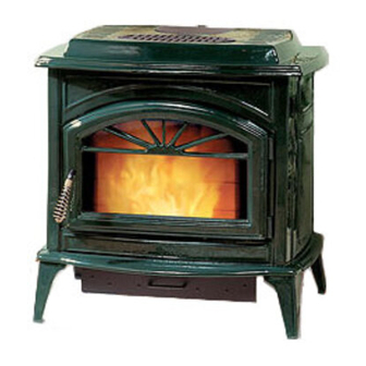
Freestanding Model
INSTRUCTIONS
T300P Series
FOR FUTURE
REFERENCE
These appliances must be properly installed and operated in order to
prevent the possibility of a house fire. Please read this entire owner's
manual before installing and using your pellet stove. Failure to follow
these instructions could result in property damage, bodily injury or even
death. Contact your local building or fire officials to obtain a permit and
information on any installation requirements and inspection require-
ments in your area.
P/N 775025M, Rev. E, 12/03
Advertisement
Table of Contents
Troubleshooting

Related Manuals for Lennox Hearth Products Traditions T300P Series


Summary of Contents for Lennox Hearth Products Traditions T300P Series
-
Page 1: Installation And Operation
PELLET FIRED STOVES RETAIN THESE Freestanding Model INSTRUCTIONS T300P Series FOR FUTURE REFERENCE These appliances must be properly installed and operated in order to prevent the possibility of a house fire. Please read this entire owner's manual before installing and using your pellet stove. Failure to follow these instructions could result in property damage, bodily injury or even death. -
Page 2: Important Warnings
Since Lennox Hearth Products has no control over the installa- tion of your stove, Lennox Hearth Products grants no warranty, implied or stated for the installation or maintenance of your stove, and assumes no re- sponsibility for any consequential damage(s). -
Page 3: Table Of Contents
It is our goal at Lennox Hearth Products to provide you, our valued customer, with an appliance that will ensure you years of trouble free warmth and pleas- ure. -
Page 4: Planning Your Installation
PLANNING YOUR INSTALLATION QUESTIONS TO ASK LOCAL BUILDING OFFICIAL A correct installation is critical and imperative for reduc- ing fire hazards and perilous conditions that can arise when wood pellet burning appliances are improperly installed. The installer must follow all of the manufac- turers’... - Page 5 6" from the back as illustrated below. *Note: When installed at clearances less than 6”, floor protection is only required to extend to the wall. 6" (153mm} T300P SERIES * Up to 6"/153mm minimum 6" (153mm} Page 5 6"...
- Page 6 The clearances allowed as shown here, do not take into account operation or serviceability requirements. CLEARANCES Standard residential or manufactured (mobile) home instal- lation. These appliances require the following minimum clearances to combustibles: MINIMUM CLEARANCES TO COMBUSTIBLES Model: T300P Manufactured (Mobile) Home or Residential Installation Series Horizontal Flue – Clearance to Directly Through...
-
Page 7: Manufactured (Mobile) Home Installation
INSTALLATION CHECK LIST It is strongly recommended that you have an authorized Lennox Hearth Products dealer install your stove. If you install your stove yourself, you should review your in- stallation plan with your authorized Lennox Hearth Products dealer. -
Page 8: Installation
INSTALLATION DAMPER ROD INSTALLATION 1. Locate rectangular cutout on bottom stove panel behind ash pan. 2. Screw damper rod into threaded hole. DAMPER ADJUSTMENT The damper rod is located under the bottom plate, on the right hand side of the stove, just behind the ash pan. - Page 9 VIDED IS NOT USED, THE JUMPER IS REQUIRED FOR THE STOVE TO OPERATE. Terminal Block for Thermostat Leave Jumper on, If Thermostat Is Not Used Remove Jumper if Thermostat Is To Be Used Jumper Model T300P Series (viewed from stove back) Page 9...
- Page 10 VENTING REQUIREMENTS It is recommended that only an authorized dealer install your pellet stove. The specified installation requirements must be followed to ensure conformity with both the safety listing of the appliance and local building codes. All clearances, installation instructions and precautions specified by the vent manufacturer must be followed.
- Page 11 INSTALLATION VENT TERMINATION Do not terminate vent in an enclosed or semi-enclosed area such as: carports, garage, attic, crawl space, under a deck, porch, narrow walkway, closely fenced area, or any location that can build up a concentration of fumes such as a stairwell, covered breezeway, etc.
- Page 12 INSTALLATION DETERMINING SIZE OF PIPE TO INSTALL To determine what diameter pipe to use in an installation (3” or 4”), first find the “equivalent pipe length” using the follow- ing guidelines, then plot this figure and the altitude on the chart. Fill out the installation chart, and calculate your total equivalent pipe length.
- Page 13 INSTALLATION INSTALLING YOUR PELLET STOVE Standard Horizontal Exhaust Installation (Direct Vent) 1. Locate the proper position for the listed type “PL” wall thimble. Avoid cutting wall studs when installing your pipe. Use a saber saw or keyhole saw to cut the proper diameter hole through the wall to accom- modate the wall thimble.
- Page 14 INSTALLATION INSTALLATION CONFIGURATIONS – Standard Horizontal Installations If you vent to the fur- thest wall, the vent pipe must maintain clearance parallel to the other wall. Note: Horizontal run of pipe requires 1/4” / 7 mm rise per foot. 3” Page 14...
- Page 15 INSTALLATION Installation Configurations / Standard Venting Options This appliance may be connected to an existing flue or by installing listed type “PL” vent pipe. If a liner is run all the way to the top of the existing chimney, the existing flue should be sealed with a steel plate.
-
Page 16: Care And Operation
CARE AND OPERATION CONTROL BOARD OPERATION Stove On / Off Button – This button will turn your stove on or off while in Manual or Automatic mode (see page 19 for details). The green on / off light at the top of control board will indicate the on / off status. - Page 17 1:26 to 2:14 depending on -4 to +4 respectively. 3. Exhaust blower operation starts (medium range volt- age). 4. Room air blower operation starts (medium range volt- age).Power LED is activated (steady green). 6. Igniter operation activated (line voltage).
- Page 18 CARE AND OPERATION Combustion Voltage Trim Steps: 1. Push button “twice” for access voltage calibration mode. 2. Identify the current calibration setting indicated by one YELLOW LED bar. 3. Push the “HEAT” control button to adjust setting UP. Each push raises the YELLOW LED bar & increases voltage 5%.
- Page 19 3. Place a small amount of an approved (non-volatile) fire starter on top of the pellets in the grate, (see your authorized Lennox Hearth Products dealer for appropriate fire starting products). DO NOT USE FLAMMABLE LIQUIDS TO START YOUR STOVE! 4.
- Page 20 CARE AND OPERATION DAMPER OPERATION The damper is a plate that helps control the amount of airflow supplied for combustion. With the damper pushed in all the way, the airflow is at its minimum. damper is pulled out, more air is allowed to flow. It will be necessary to monitor the appearance of the flame during the first 4-8 bags of pellets.
- Page 21 PLEASE NOTE: Lennox Hearth Products has no control over the manufacturing of pellet fuel and will not be held responsible for poor stove performance or any damage caused by inferior pellet fuels.
-
Page 22: Routine Maintenance
ASH PAN The ash pan will have to be emptied periodically, de- pending on amount of fuel consumed. The T300P Series ash pan is pulled straight out using the black pull knob located on the front of the ash pan (see following pic- ture). - Page 23 ROUTINE MAINTENANCE PHOTOEYE The photoeye is positioned to view the flame from the top of the auger feed tube. It is located below the auger cover and can be accessed from inside the hopper for annual maintenance or replacement (if necessary). Photoeye Access Inside Hopper Using a 11/32"...
- Page 24 ROUTINE MAINTENANCE Clean-Out Tee w/ Cover Removed * (Minimum Frequency of 1-2 months) HEAT EXCHANGER TUBES ONLY CLEAN HEAT EXCHANGER TUBES AFTER STOVE HAS COOLED DOWN. A rod is located above the heat exchange baffle (inside of firebox) is used for cleaning the tubes.
- Page 25 Do not apply oil to any part of the blower. Doing so may cause damage. SMALL AREA PAINT TOUCH-UP (Model T300P only) Using one small piece of 320 grit sand paper and lightly sand the blemish so that the edges are “feathered” or smooth to the touch between the painted and bare sur- faces.
-
Page 26: Specifications
SPECIFICATIONS - Model T300P Series Flue Size Width, Overall Depth, Overall Height Floor to Rear Flue Center Facing Back of Unit, Outside Edge of Left Leg To Center of Rear Flue Outlet Floor to Rear Outside Air Inlet Facing Back of Unit... -
Page 27: Definitions
DEFINITIONS AIR WASH To inhibit buildup of soot on the door glass, air is deliv- ered to the glass through an air wash system located in the doorframe surrounding the glass. AUGER It transfers the fuel down the burner tube into the burn grate. -
Page 28: Wiring Diagram
WIRING DIAGRAM Page 28... -
Page 29: Troubleshooting
Adjust the damper to reduce combustion airflow. Refill hopper. Check to be sure that there is no blockage in the pressure tap or hose. Have your authorized Lennox Hearth Products dealer diagnose the problem and clean or replace any nec- essary parts. -
Page 30: Troubleshooting
Block excessive sunlight. Call your authorized Lennox Hearth Products dealer if problem persists. Check igniter element fuse in rear stove compartment. Call your authorized Lennox Hearth Products dealer. See alternate manual lighting procedure Prime the feed system (see page 18, Initial Start Up/Empty Hopper or Feed Tube). -
Page 31: Replacement Parts List / Diagrams
REPLACEMENT PARTS LIST Door Parts & Body Components Item # Part # Description 20953002 Door Assembly, Black Painted – Model T300P 20953012 Door Assembly, Black Enamel – Model T301P 20953052 Door Assembly, Green Enamel – Model T305P 20953082 Door Assembly, Sand Enamel – Model T308P 26M81 Gasket Kit, Door, 3/4”... - Page 32 REPLACEMENT PARTS LIST Auger Item # Part # Description 12041300 Collar & Screw Set, Auger (3pc.) 20950087 End Flange, Auger 61050003 End Plate Gasket, Auger (5pc.) 11756300 Shaft, Auger Misc. Parts Item # Part # Description 17150029 Damper Rod Assembly, Kit 20950110 Gasket, Quick Disconnect 20950014...
- Page 33 REPLACEMENT PARTS DIAGRAMS Page 33...
- Page 34 REPLACEMENT PARTS DIAGRAMS Page 34...
-
Page 35: Optional Accessories
OPTIONAL ACCESSORIES Note: Install and use accessories per instructions provided with the accessory kit. Optional Accessories Item # Catalog # Model # 14M16 TT – G H0252 DLS – T30 14M81 QDPC – 4 70K99 TSPK – B Description Trivet, Gold Plated Log Set Quick Disconnect Pipe Connector, 4”... -
Page 36: Installation Tips
INSTALLATION TIPS Page 36... -
Page 37: Simple Operating Instructions
SIMPLE OPERATING INSTRUCTIONS LABEL Page 37... -
Page 38: Safety / Listing Label
T300P PELLET STOVE SAFETY LABEL Note that your serial number is printed on the safety label located on the back of the stove. Your stove’s serial number is preceded by a “WH-”(Example WH-0000000). Page 38... -
Page 39: Ownership Records
Dealer’s Name: Dealer’s Address: City: Serial Number: Notes: SERVICE AND MAINTENANCE LOG Service Service Service Date Technician Description State: Date of Purchase: Page 39 Zip Code: Date Installed:... - Page 40 1110 West Taft Avenue Orange, CA 92865...