Sony SR-R4 Operation Manual
Portable memory recorder
Hide thumbs
Also See for SR-R4:
- Brochure (17 pages) ,
- Operation manual (61 pages) ,
- Product manual (59 pages)

Related Manuals for Sony SR-R4


Summary of Contents for Sony SR-R4
-
Page 1: Sony Corporation
PORTABLE MEMORY RECORDER SR-R4 CONTROL PANEL SRK-CP1 Sony Corporation SR-R4 Printed in Japan [English] OPERATION MANUAL (SY) 2012.9 32 1st Edition (Revised 4) 4-412-781-05 (2) © 2011 Printed on recycled paper. - Page 2 Before operating the unit, please read this manual thoroughly and retain it for future reference. WARNING To reduce the risk of fire or This HD Portable Memory Recorder is electric shock, do not classified as a CLASS 1 LASER PRODUCT. expose this apparatus to Laser Diode Properties rain or moisture.
- Page 3 Part 15 of the FCC For the customers in Europe Rules. These limits are designed to provide The manufacturer of this product is Sony reasonable protection against harmful Corporation, 1-7-1 Konan, Minato-ku, interference when the equipment is operated Tokyo, 108-0075 Japan.
- Page 4 Pour les clients en Europe Pour utiliser ce produit en toute sécurité, Le fabricant de ce produit est Sony évitez l’écoute prolongée à des pressions Corporation, 1-7-1 Konan, Minato-ku, sonores excessives. Tokyo, 108-0075 Japon.
- Page 5 Bitte lesen Sie dieses Handbuch vor der Benutzung des Geräts sorgfältig durch und bewahren Sie es zum späteren Nachschlagen auf. WARNUNG Um die Gefahr von Bränden oder elektrischen Schlägen zu verringern, darf dieses Gerät nicht Regen oder Feuchtigkeit ausgesetzt werden. Um einen elektrischen Dieser Tragbarer HD-Speicherrecorder ist Schlag zu vermeiden, darf...
- Page 6 Für Kunden in Europa Der Hersteller dieses Produkts ist Sony Corporation, 1-7-1 Konan, Minato-ku, Tokyo, 108-0075 Japan. Der autorisierte Repräsentant für EMV und Produktsicherheit ist Sony Deutschland GmbH, Hedelfinger Strasse 61, 70327 Stuttgart, Deutschland. Bei jeglichen Angelegenheiten in Bezug auf Kundendienst...
-
Page 7: Table Of Contents
Table of Contents Table of Contents Date Settings ......... 27 Chapter 1 : Overview Features........... 9 Chapter 4 : Recording and Playback System Configuration Example .... 9 Names of Parts........10 Recording Preparations and Operations ........28 Overall View ......10 Left Side View...... - Page 8 Chapter 5 : Menu Details MPEG-4 VISUAL PATENT PORTFOLIO LICENSE....79 TC Setup Menu ........51 Index ............80 AUDIO Setup Menu ......54 SR-R4 Supported Formats and SYSTEM Setup Menu ......56 Maximum Recording Times (Approximate) ........ 82 Appendix Maintenance and Inspections....62 Note About the CAMERA Connector ......
-
Page 9: Chapter 1 : Overview
Overview Chapter Features System Configuration Example The SR-R4 is a portable memory recorder of the The following figure shows a system configured SRMASTER series, featuring an F65 dockable around the SR-R4. CAMERA port and using the newly developed SRMemory card for the recording media. -
Page 10: Names Of Parts
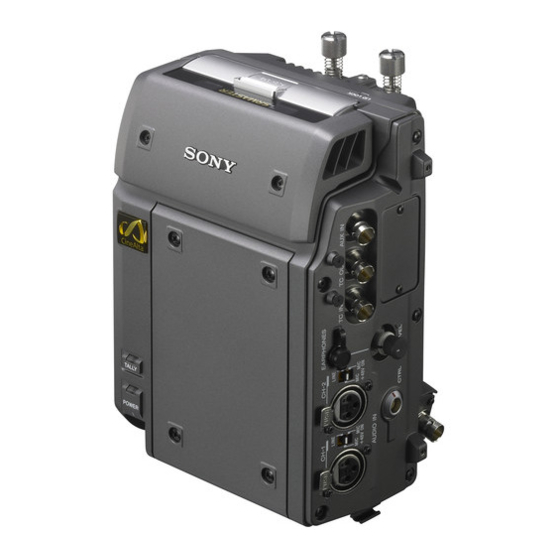
Left Side View Names of Parts For detailed information on functions and usage, see the pages indicated in brackets. Overall View AUDIO INPUT CH-1, CH-2 (analog audio input channel 1, 2) connectors (3-pin XLR, female) and input selection switches Set the input selection switches as follows, depending on the type and level of the input audio. -
Page 11: Rear And Right Side View
Note When using the AUX IN connector, an HD SDI signal that is synchronized with the F65 docked to the unit must be input. Docking screws (page 18) CAMERA connector (page 17) CTRL PANEL (Control Panel) connector (page 16) AUX OUT connector (for future use) Rear and Right Side View Power switch (page 21) Setting the switch to the ? side turns power... -
Page 12: Control Panel (Srk-Cp1, Option)
Control Panel (SRK-CP1, Option) For information on how to use the control panel, see “Basic Menu Operations” (page 24). KEY INHI HOME SELECT/ENTER LIGHT BACK SR-R4:CAM VIDEO STOP KEYINHI ADJUST RECINHI AUDIO EJECT STOP PLAY IN DLY: MK: --:--:--:-- SYSTEM... -
Page 13: Display
11 below when the HOME button is pressed while holding down the FUNC button. IN DLY: MK: --:--:--:-- FILENAME:(NEXT)A001C001_120530RT SYS: F65RAW 23.98P LOCAL ENCODE: F65RAW-SQ 5min 16.6V SR-R4:CAM STOP KEYINHI RECINHI IN DLY: MK: --:--:--:-- FILENAME:(NEXT)A001C001_120530RT LOCAL IN DLY: MK: --:--:--:-- ENCODE F65RAW 16.5V... - Page 14 SRMemory card remaining capacity indication Shows the remaining space on the SRMemory card calculated as remaining time, using the current recording settings. SR-R4:CAM KEYINHI When the remaining time is less than 3 RECINHI STOP minutes, the indication flashes.
-
Page 15: Chapter 2 : Preparation
Unit The steps that are required before starting to use Attach the CP bracket supplied with the Control the SR-R4 are listed below. Panel (SRK-CP1, Option) to the unit, and connect the unit and the control panel with the control When mounting Control Panel (SRK-CP1, panel cable. - Page 16 • Do not cross the cord below the clamps. • Make sure that the bottom of the cord does not extend beyond the bottom of the SR-R4. • If the SR-R4 cannot be docked on the F65, refer to the above and check the cord bundle again. Note...
-
Page 17: Connect F65
1 Align the base of the unit with the base Connect F65 of the F65 as shown in the diagram. The unit mounts onto the rear of the F65. Tips • When mounting the unit, first mount the F65 on a tripod and secure it such that it does not move. - Page 18 Removing the Unit from the F65 Press down firmly on the point shown in the diagram, and fasten the docking Press down firmly on the point shown in screws. the diagram, and loosen the docking Note screws. Do not push down on the lid. Remove the unit by lifting it.
-
Page 19: Mount Control Panel On The F65
Slide the control panel into the CP Mount Control Panel on bracket. the F65 Attach the Control Panel (SRK-CP1, Option) to the F65, and connect the unit and the control panel with the control panel cable. Attach the outside bracket supplied with the control panel to the side of the F65, and fasten using the 4 supplied screws (M3 ×... -
Page 20: Attach The Battery Pack
To remove the control panel Attach the Battery Pack Grasp the underside of the CP bracket and push it in the B direction to release the lock. Then slide the control panel out. To attach the battery pack, the following options must be installed using the BKP spacer supplied with the unit. -
Page 21: Turn Power On
BKP-L551 fastening L screws Note To prevent the risk of data corruption, do not interrupt the F65 DC IN power supply while the SR-R4 is turned To accessory If power switch is turned off while an SRMemory card is mounted, the unit will not power down immediately, to protect the data on the card. -
Page 22: Insert Srmemory Card
Supported SRMemory cards For details on SRMemory cards supported by the • When fully charged, all seven segments are lit. unit, see “SR-R4 Supported Formats and Maximum As the battery pack discharges, the segments go Recording Times (Approximate)” (page 82). -
Page 23: Formatting An Srmemory Card (File System Format)
(page 71) in the Write-protect switch Slide “Troubleshooting” section. fully to the right. When the card is inserted in the SR-R4 in this To remove the SRMemory card condition, the indication “REC INHI” appears, and recording is not possible. -
Page 24: Chapter 3 : Basic Menu Operations
Basic Menu Operations Chapter The menu system of the SR-R4 consists of the Serve for Selecting a Menu following four menus. Menu Overview Selecting a menu TC Setup Serves for making time code Press the respective menu selection button. settings. -
Page 25: Locking The Controls
KEY INHI switch RUN MODE R RUN TCG SET OTHERS KEY INHI HOME SELECT/ENTER LIGHT BACK SR-R4:CAM VIDEO STOP KEYINHI ADJUST RECINHI AUDIO S T O P 00 :0 0: 00 :0 0 S R -R 4 :C A M... -
Page 26: Signal Format Settings
Selecting the Signal Format Making “SYSTEM FORMAT” settings S T O P 0 0 : 0 0 :0 0 : 0 0 SR-R4:CAM TC G Press the SYSTEM button. After settings are complete, select SET. The SYSTEM Setup menu appears. -
Page 27: Display Settings
Display the System menu, and then LIGHT switch select and confirm “OTHERS” t select and confirm “SET DATE.” KEY INHI HOME SELECT/ENTER LIGHT Set the year, month, day, local time, and BACK SR-R4:CAM VIDEO STOP KEYINHI ADJUST UTC (Coordinated Universal Time) RECINHI AUDIO EJECT STOP... -
Page 28: Recording Preparations And Operations
EARPHONES jack. jack. Cancel record REC INHI in the page 32 inhibit if the SYSTEM Setup SR-R4:CAM S T O P 00:00:00:00 system is set to menu 3Signal to record record inhibit mode. ANA1 to ANA2: Analog signals input via... -
Page 29: Setting The Recording Levels
SEL.” The Phone Select screen appears. Average Average 1 Select and confirm the channel SR-R4:CAM S T O P 00 : 0 0 : 00 : 0 0 T CR number (1 to 16) t2 press the SELECT/ENTER dial to select the ADD: Simple addition channel L/R setting. -
Page 30: Setting The Time Code And User Bits
CH12 UNI CH16 4000 FINE FINE UNI/VAR RESET SR-R4:CAM S T O P 0 0 : 0 0 : 0 0 : 0 0 Channel numbers Recording level settings S T O P 0 0 :0 0: 00 :0 0... -
Page 31: Tcg Mode
Time Code User Bit Timer-1 Timer-2 S T O P 00 :0 0: 00 : 00 SR-R4:CAM TC R To select the time code to record The time code can be selected in the following menu. Menu item Time code... -
Page 32: Recording
(page 32). S T O P 0 0 : 0 0 : 0 0 : 0 0 SR-R4:CAM As with the time code, all digits can be returned to 0 with 4Rotate the dial to change the value “TIMER RESET.”... -
Page 33: Playback Preparations And Operations
When the REC INHI indicator is lit Playback Preparations Record inhibit is set. • Set SYSTEM Setup > REC INHI to “OFF.” and Operations (see page 60) • Check that FS LOCK for the SRMemory card is not locked. (see page 61) •... -
Page 34: Playback
You can also perform this during jog Playback playback. Insert the SRMemory card to play Turn the ADJUST knob while pressing back. the FUNC button. Shuttle playback is performed according to For details, see “To insert the SRMemory card” the position of the knob and the speed at (page 22). -
Page 35: How To Use The Recording And Playback Operation Buttons
How to Use the Recording and Playback Operation Buttons Button Function when pressed alone Function when pressed with FUNC button STOP button Stops the recording and playback If pressed during the STOP or REC operation. PAUSE state, the unit enters Standby If pressed during Standby Off mode, Off mode. - Page 36 Button Function when pressed alone Function when pressed with FUNC button F FWD button and indicator Moves to the beginning of the next Executes a forward direction search. (NEXT) file. With each press, the search speed changes in the order of x2 t x5 t x8 t x16 t x32 t x2 ...
-
Page 37: Cuing Files
To open a MARK IN point Cuing Files Opening the current MARK IN point Display the HOME screen, and while a valid MARK IN point set and active, press the PAUSE button while holding down the FUNC button. The file opens at the currently active MARK IN By setting a MARK IN point during recording or point. -
Page 38: File List Operations
FILENAME DEFAULT CAMERA ID KEY MAP KEY INHI REEL NO. REC INHI POWER BATTERY SRMemory OTHERS SR-R4:CAM S T O P 0 0 : 0 0 : 0 0 : 0 0 The File list window appears. FILE LIST Operations... -
Page 39: File List
SR-SQ 10bit Folder Name: E 0 0 9 C 0 5 4 _ 1 2 0 4 2 3 8 4 The detailed information for the file at the cursor SR-R4:CAM S T O P 00 :0 0: 00 :0 0 position is displayed. -
Page 40: Performing File Operations
S e l e c t F u n c t i o n S T O P 0 0: 00 : 00 :0 0 SR-R4:CAM Changing the File Display Order 2Select the operation The display order of files in the file list can be RENAME: Renames the file. -
Page 41: Displaying And Opening Mark In Points
SR-SQ 10bit Folder Name: F I L E 0 0 0 0 0 0 0 5 format SR-R4:CAM S T O P 0 0 :0 0 : 0 0 :0 0 To properly play back files that cannot be played Notes in the current system format (i.e., files displayed... -
Page 42: Sr Motion
• When using the SR Motion function, be sure to check the version of the F65 docked to the unit. For details on versions, contact a Sony service representative. What is the target frame frequency? Normally, the frame frequency of recorded... - Page 43 Typical examples of using SR Motion Slow motion example played back in slow motion at 24/60 = 0.4 times The following example illustrates shooting and normal playback speed. recording with the Select FPS function at the If you set the format for recording in accordance system frequency of 59.94p, and playback at the with the target frame frequency (system system frequency of 23.98P.
- Page 44 Quick motion example When video recorded at 6 FPS (recording only the The following example shows shooting and valid frame images at a frame rate of 6 FPS when recording at a system frequency of 59.94P and a shooting) is played back at 24 FPS, it is played frame rate of 6 FPS, and playback at a system back in quick motion at 24/6 = 4 times normal frequency of 23.98P.
- Page 45 Relation between the target frame frequency and time code When the system frequency is 23.98 Hz, the time advances from the 0 to 23 frames of the target code normally advances from 0 to 23 frames, and frame frequency. If 1 second is recorded with this becomes the time code of the recorded these settings beginning from the 00 second 00 material (target frame frequency).
-
Page 46: Sr Motion Operation Flow
SR Motion Operation Flow Connect the unit to the camera Set the target frame frequency (playback time code) Select the system format to use during shooting Select the SR Motion mode (function) Set the number of frames to shoot (FPS) Shoot Review Select FPS Function... - Page 47 Relation between the number of frames shot and number of playback frames (Basic concept of Select FPS) To obtain the desired slow or quick motion effects transferred data is padded with frames using the Select FPS function, it is necessary to (ineffective frames) in which no signal is set the appropriate number of frames to shoot.
- Page 48 SEL-FPS : 59.94P MODE : ON SIGNAL : 48FPS move the cursor to and confirm [SET]. SR-R4:CAM STOP KEYINHI RECINHI 1 SYSTEM FORMAT 2 Set to match [ x 0.500 ] the camera...
- Page 49 MODE : ON SIGNAL : 48FPS fourth frame. [ x 0.500 ] To turn Select FPS on/off quickly SR-R4:CAM SR-R4:CAM STOP KEYINHI In the HOME screen, press the SELECT/ENTER RECINHI dial while holding down the STOP button. The SYSTEM Setup menu will open with the...
-
Page 50: File Naming System
• If a blank SRMemory card is inserted, the reel number File Naming System will increase by one from the last recorded file. Example: If recording is performed on a blank card after recording up to “D001CXXX_XXXXXXXX” on the previously inserted card The next recorded file will be named “D002C001_XXXXXXXX.”... -
Page 51: Chapter 5 : Menu Details
Menu Details Chapter • The settings displayed in bold are the factory default settings. • The settings enclosed in [] are the settings as displayed in the settings windows. TC Setup Menu Setting Item Settings TIMER SEL Selects the type of time data to display on the display. TC [Time Code]: Displays the time code: Displays the time code. - Page 52 Setting Item Settings RUN MODE Selects the run mode of the internal time code generator. F RUN [Free Run]: Advances the time code while the power is on. R RUN [Rec Run]: Advances the time code only during recording. TCG SET DF/NDF Sets the frame count mode.
- Page 53 Setting Item Settings OTHERS TC OUT Selects the time code to output from the TC OUT Other settings related connector. to the main time code AUTO [Auto]: During playback, the time code read by the internal time code reader. During recording or when in E-E mode, the time code generated by the time code generator.
-
Page 54: Audio Setup Menu
AUDIO Setup Menu Setting Item Settings INPUT SEL TRACK1 Selects the signal to assign to track 1. Selection of input ANA1 [Analog CH1] to ANA2 [Analog CH2], OFF signals AUX1 [AUX CH1] to AUX16 [AUX CH16] TRACK2 Selects the signal to assign to track 2. Same settings as TRACK1 (ANA2) TRACK3 Selects the signal to assign to track 3. - Page 55 Setting Item Settings METER TYPE Sets the display range of the audio level meters. PEAK [Full Peak]: Displays 0 dBFS as the peak value. REF [Full Ref]: Displays the reference level (+4 dBu) as 0 dB. FINE [Fine]: Displays a scale with 0.25 dB steps and -20 dB at the center.
-
Page 56: System Setup Menu
SYSTEM Setup Menu Setting Item Settings FILE LIST FILE LIST Displays a list of recording files and allows recording files to be selected and file operations to be performed. For details, see “FILE LIST Operations” (page 38). SORT Sorts the files in the FILE LIST screen. DATE: Date order NAME: Name order DURATION: Order of file recording length... - Page 57 Setting Item Settings SYSTEM FORMAT RAW/HD Sets the recording mode. Settings of signal After selecting and confirming [SET] to change this formats setting, you must restart the F65 as instructed in the message that appears. F65RAW: Records in F65RAW format. F65RAW-HFR: Records in F65RAW-HFR format.
- Page 58 Setting Item Settings PB FUNCTION IN POINT Specifies time codes for setting the time data (IN points) used for cuing. When an IN point is set, the IN point is displayed in “IN:XX:XX:XX:XX” format in the time data indication of the HOME screen. For details on cuing using IN points, see “Cuing via Time Code Entry (IN Points)”...
- Page 59 Setting Item Settings LIGHT OFF Sets whether or not to turn the backlight off after a set Settings of display time. backlight DIS [Disable]: Does not turn the backlight off. 5sec [5sec]: Turns the backlight off after 5 seconds. 10sec [10sec]: Turns the backlight off after 10 seconds. 30sec [30sec]: Turns the backlight off after 30 seconds.
- Page 60 Setting Item Settings REC INHI OFF [Off]: Does not prohibit recording. Settings of recording inhibit mode ON [On]: Prohibits recording. POWER POWER LED Controls the POWER indicator. Settings to reduce ON [On]: Lit normally power consumption LOW [Low]: Dimly lit OFF [Off]: Not lit TALLY LED Controls the tally lamp.
- Page 61 Setting Item Settings SRMemory INFO DISP Displays SRMemory card information. SRMemory related FS LOCK Lock setting for the SRMemory card to disable file settings recording/deletion. When the write-protect switch is WP, this setting cannot be configured. LOCK: Locked. UNLOCK: Unlocked. FORMAT Formats the SRMemory card.
-
Page 62: Appendix
Appendix Press point 1 on the CAMERA Maintenance and connector using your finger or other object to open the protective shutter Inspections and expose the optical contacts. Shutter Note About the CAMERA Connector Transmission errors may occur if there is any dust Once the shutter opening jig is attached, or other matter adhering to the face of the optical open the shutter and check that you can... -
Page 63: Specifications
Video Specifications F65RAW format, F65RAW-HFR format HD SStP 4:2:2 format Sampling frequency Y: 74.25 MHz Cb/Cr: 37.125 MHz General Quantization 10 bits Compression Recording format MPEG4 SStP F65RAW, F65RAW-HFR, HD SStP HD SStP 4:4:4 format Power supply Sampling frequency 11 to 17 V DC RGB: 74.25 MHz Power consumption Quantization... -
Page 64: Input/Output Connectors
TO RECORD CONTENT OF ANY TYPE. AUX IN • Always verify that the unit is operating properly BNC (1) before use. SONY WILL NOT BE LIABLE FOR HD SDI embedded audio (1.485 Gbps) DAMAGES OF ANY KIND INCLUDING, BUT (SMPTE-292M compliant) -
Page 65: Error Messages And Warning Messages
If the same error message appears again when the E050 MEDIA IF Cannot communicate ERROR with the SRMemory system is powered on, contact a Sony service card. representative. Error Messages and Warning Messages... -
Page 66: About Warning Messages
Code Message Meaning About Warning Messages E051 UNMOUNT An interface error ERROR occurred when ejecting If an error is detected, a warning message code the SRMemory card. appears in the operation status and warnings E052 MOUNT An interface error section of the HOME screen (see page 13) and at ERROR occurred when the bottom left of each Setup menu screen (model... - Page 67 Code Message Meaning Warning messages W01A TASK STUCK Transmission for a portion of a multitask Code Message Meaning may have failed. W001 PB FREQ There is a mismatch W01F PLAYER Recording is not possible MISMATCH between the configured MODE in the current state. system frequency and the W022 AUDIO PLL The audio clock is not...
- Page 68 Code Message Meaning W074 CAM FMT The camera and the MISMATCH format settings do not match. W076 CAM VOL The camera supply voltage is too low. W077 CAM Cannot detect a signal MISSING from the camera. W078 CAM OPT The received optical level CARE from the CAMERA connector is low.
-
Page 69: Warning System
Warning tones are only output if the BEEP (PHONE) > WARN (see page 55) setting in the AUDIO Setup menu is HIGH or LOW. Warning tones Alarm tones Tally indicator Description SR-R4 Countermeasures operation 1 beeps/second 1 beeps/second 1 flashes/... - Page 70 Warning tones Alarm tones Tally indicator Description SR-R4 Countermeasures operation 1 beeps/second 1 beeps/second 1 flashes/ second 4 beeps/second 4 beeps/second 4 flashes/ second Continuous tone Continuous tone — SRMemory Recording, Perform recording, processing (i.e., playback, and playback, or other...
-
Page 71: Troubleshooting
A warning massage and a message asking Troubleshooting whether you want to perform salvaging or formatting appears on the display. Notes • If REC inhibit is set to “ON” in the SYSTEM menu, set it to “OFF.” • After you start the salvaging process, the process cannot be stopped. - Page 72 Video Problem Cause Countermeasures Picture is gray. The format of the input signal is The picture is gray when an input signal format different from the system format. is different from the system signal format. Set to the same format as the F65. The input signal is unstable.
- Page 73 Other Problem Cause Countermeasures Power goes off. The current limiter of the power Adjust the limiter, taking into take account the source was activated. inrush current when powering on and when switching modes. Cannot record. SRMemory card is write-protected. Return the write-protect switch to the original position.
-
Page 74: About Recording/Playback Formats
About Recording/Playback Formats When Select FPS is ON Select Signal Frame ENCODE Format (TC) F65RAW- F65RAW- SR-HQ SR-SQ SR- setting (system (target SQ/Lite 12 bit Lite frame frame frequency) frequency) F65RAW 24/25 — — — — 23/29 — — — —... -
Page 75: Lip Sync Correction
Lip Sync Correction Depending on the system format and the system configuration, you may need to correct the amount of delay in the audio input signal in relation to the amount of delay in the video signal from the camera (lip sync correction). -
Page 76: Automatic File Name Configuration In Response To Changes In Srmemory Cards And Settings
Automatic File Name Configuration in Response to Changes in SRMemory Cards and Settings Depending on the condition of the SRMemory Remove the SRMemory card, and card that is inserted in the unit or whether the insert another blank SRMemory card camera ID is changed, the name of the next (i.e., a recently formatted card or a card recorded file will be automatically configured. -
Page 77: When The Camera Id Is Changed
“F” in the “FILE LIST” of the “Memory Stick Duo” media and “Memory Stick PRO SYSTEM Setup menu. Duo” media cannot be used as is in the SR-R4. In order When you change the camera ID setting, the to use these “Memory Stick” types, a separately “REEL NO.”... - Page 78 - Under direct sunlight - Very humid or subject to corrosive substances • To prevent data loss, make backups of data frequently. In no event will Sony be liable for any loss of data. Labeling position • Unauthorized recording may be contrary to the provisions of copyright law.
-
Page 79: Mpeg-4 Visual Patent Portfolio License
MPEG-4 VISUAL PATENT PORTFOLIO LICENSE THIS PRODUCT IS LICENSED UNDER THE MPEG-4 VISUAL PATENT PORTFOLIO LICENSE FOR THE PERSONAL AND NON- COMMERCIAL USE OF A CONSUMER FOR (i) ENCODING VIDEO IN COMPLIANCE WITH THE MPEG-4 VISUAL STANDARD (“MPEG-4 VIDEO”) AND/OR ii) DECODING MPEG-4 VIDEO THAT WAS ENCODED BY A CONSUMER ENGAGED IN A PERSONAL AND NON-COMMERCIAL... -
Page 80: Index
Index INPUT SEL 54 KEY INHI 59 KEY INHI switch 12 KEYMAP 59 Accessories supplied 64 ADJUST knob 12 Adjusting playback audio levels 33 AUDIO INPUT CH-1, CH-2 connectors 10 LCD 59 AUDIO INPUT CH-1, CH-2 input selection LEVEL knob 10 switches 10 LID LOCK indicator 10 Audio level meters 13... - Page 81 Recording and playback operation buttons 12, 35 Recording preparations 28 Recording/playback formats 74 RUN MODE 52 Salvaging 71 Screen saver 27 Select FPS function 46 Setting the audio signals 28 Setting the recording levels 29 Signal format indication 14 Signal format settings 26 Specifications 63 SR Motion 42 SRMemory card 22...
-
Page 82: Sr-R4 Supported Formats And Maximum Recording Times (Approximate)
SR-R4 Supported Formats and Maximum Recording Times (Approximate) - Page 83 SR-R4 Supported Formats and Maximum Recording Times (Approximate)
- Page 84 SR-R4 Supported Formats and Maximum Recording Times (Approximate)
- Page 85 The material contained in this manual consists of information that is the property of Sony Corporation and is intended solely for use by the purchasers of the equipment described in this manual. Sony Corporation expressly prohibits the duplication of any portion of this manual or the...