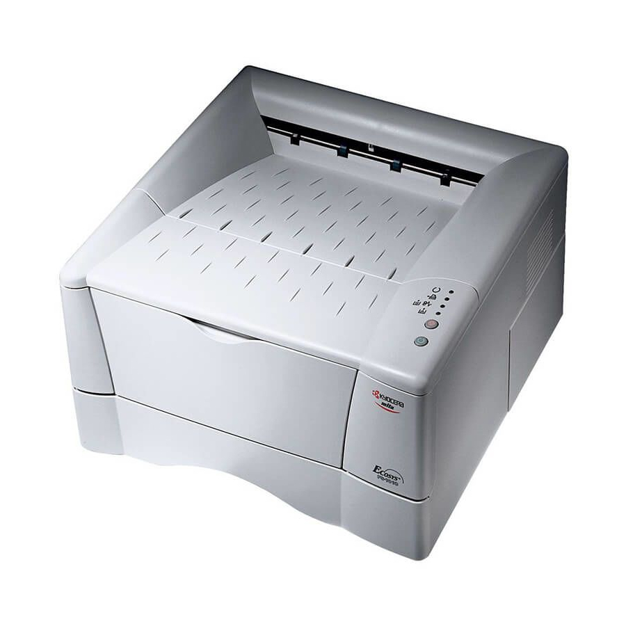
Kyocera FS-1010 Operation Manual
Ecosys page printer
Hide thumbs
Also See for FS-1010:
- Command reference manual (410 pages) ,
- User manual (154 pages) ,
- Manual (2 pages)
Table of Contents
Advertisement
Advertisement
Table of Contents

Related Manuals for Kyocera FS-1010


Summary of Contents for Kyocera FS-1010
- Page 1 Table of Contents Page Printer Operation Guide...
- Page 2 (contents of its read-only memory). This manual, any copyrightable subject matter sold or provided with or in connection with the sale of the page printer, are protected by copyright. All rights are reserved. Copying or other reproduction of all or part of this manual, any copyrightable subject matter without the prior written consent of Kyocera Mita Corporation is prohibited.
-
Page 3: Limited Warranty
IBM PROGRAM LICENSE AGREEMENT THE DEVICE YOU HAVE PURCHASED CONTAINS ONE OR MORE SOFTWARE PROGRAMS (“PROGRAMS”) WHICH BELONG TO INTERNATIONAL BUSINESS MACHINES CORPORATION (“IBM”). THIS DOCUMENT DEFINES THE TERMS AND CON- DITIONS UNDER WHICH THE SOFTWARE IS BEING LICENSED TO YOU BY IBM. IF YOU DO NOT AGREE WITH THE TERMS AND CONDITIONS OF THIS LICENSE, THEN WITHIN 14 DAYS AFTER YOUR ACQUISITION OF THE DEVICE YOU MAY RETURN THE DEVICE FOR A FULL REFUND. - Page 4 Typeface Trademark Acknowledgement All resident fonts in this printer are licensed from Agfa Corporation. Helvetica, Palatino and Times are registered trademarks of Linotype-Hell AG. ITC Avant Garde Gothic, ITC Bookman, ITC ZapfChancery and ITC Zapf Dingbats are registered trademarks of International Type- face Corporation.
-
Page 5: Table Of Contents
3.3.2 Errors Requiring Service Personnel Attention... 3-8 3.3.3 Error Messages... 3-11 3.3.4 Normal Indicator Display ... 3-13 3.4 Correcting a Paper Jam... 3-14 3.4.1 Jam at the Face-down and Face-up Trays ... 3-14 3.4.2 Jam at the Paper Cassette... 3-15 3.4.3 Jam Inside the Printer... 3-15... - Page 6 B.3.1 RS-232C Interface ... B-7 B.3.2 RS-422A Interface ... B-8 B.4 RS-232C/RS-422A Protocol ... B-10 B.4.1 PRESCRIBE FRPO D0 Command ... B-11 B.5 RS-232C Cable Connection... B-12 B.5.1 Obtain a Suitable RS-232C Cable ... B-12 B.5.2 Connecting the Printer to the Computer ... B-12...
- Page 7 Contents Printer Specifications ... C-1 Appendix C C.1 Printer Specifications... C-2 Glossary ... Glossary-1 Index ... Index-1...
-
Page 8: Introduction
Introduction The Kyocera Mita page printer has many desirable features, such as EcoPrint function that reduces the power consumption and Auto Media Type Selection function that selects automatically media before print. This section explains the following topics: • Guide to the Manuals •... -
Page 9: Guide To The Manuals
KX Printer Driver Installation Guide that is included with the printer. • For information on how to use the printer driver software, refer to the KX Printer Driver Operation Guide that is included on the Kyocera Mita Document Library CD-ROM. -
Page 10: Guide To The Operation Guide
This chapter explains how to handle printer problems that may occur, such as paper jams. Chapter 4 Paper Selection This chapter explains the types of paper that can be used with the printer. Chapter 5 Fonts This chapter explains about and lists the printer’s internal fonts. -
Page 11: Chapter 1 Basic Operations
Basic Operations Chapter 1 This chapter explains the following topic: • Operator Panel... -
Page 12: Operator Panel
Operator Panel The operator panel on top of the printer consists of four indicators and two keys. The four indicators light, flash, and go off in combination, indicating the printer’s status. The keys perform operations, such as canceling data, switching the printer mode between online and offline status, and printing status pages. -
Page 13: Indicators
If such a message appears, operation resumes when this key is pressed. (The KM-NET for Clients utility is used for making printer setting from a computer and is contained on the Kyocera Mita Software Library CD-ROM that is supplied with the printer. -
Page 14: Status Page
Hardware Information Page Information Network Status Interfaces Test pattern Items and values on the status page may vary depending on the printer’s firmware version. FS-1010 Page Printer STATUS PAGE Firmware Version: Memory... - Page 15 This shows the option(s) currently installed in the printer. 7 — Emulation This shows all available emulations and the currently selected emulation (marked with an asterisk). The printer is shipped from the factory with PCL 6 emulation selected. 8 — Error Log This shows the last three instances of the following six types of errors, listed in order of occurrence: KPDL Error Press GO;...
- Page 16 (marked with an asterisk). The Font section shows the font that is automatically selected when the printer starts up (default font). It is possible to set different default fonts for each interface. 11 — KIR Test Pattern...
-
Page 17: Chapter 2 Maintenance
Chapter 2 This chapter explains how to replace the toner container and how to clean parts such as the registration roller and charger wire. This chapter explains the following topics: Maintenance • Toner Container Replacement • Cleaning... -
Page 18: Toner Container Replacement
6,000* printed pages. * In the case of a new printer in which a toner kit has been installed for the first time, the number of copies that can be printed will be approximately 3,000. -
Page 19: Replenishing Toner
Toner Container Replacement 2.1.2 Replenishing Toner Open the printer’s top cover. Pull lock lever #1 to the release (UNLOCK) position, then pull lock lever #2 to the release (right) position. Lock Lever #1 Gently remove the old toner container. Put it in the supplied plastic bag and dispose of it. - Page 20 New Toner Container Carefully remove the protective seal (orange-colored). Install the new toner container in the printer. Push firmly on the top of the container at the positions marked PUSH HERE until you hear it click in place.
- Page 21 • After you have replaced the toner container, be sure to reset the toner counter. Next time you turn on the power to the printer, keep pushing key until the Ready indicator lights up.
-
Page 22: Cleaning
Cleaning 2.2.1 Printer Interior To avoid print quality problems, the interior of the printer must be cleaned with every toner container replacement. Cleaning should be done from time to time to avoid print quality problems. To avoid print quality problems due to paper dust and debris, clean the interior of the printer in the following manner. - Page 23 Cleaning Never stand the process unit on end. Use the supplied wiper cloth to clean dust and dirt away from the registration roller (metal). Transfer Roller While cleaning, be careful to avoid touching the transfer roller (the black roller). Slide the charger cleaner knob (green-colored) back and forth 2 to 3 times, then return it to its CLEANER HOME POSITION Charger Cleaner Knob After cleaning, make sure you restore the charger cleaner to its home...
- Page 24 CLEANER HOME POSITION of the page the next time you use the printer. After cleaning is done, put the process unit back in the printer. To do so, carefully align the guides at both ends of the process unit with the slots in the printer.
-
Page 25: Chapter 3 Troubleshooting
Chapter 3 This chapter explains how to handle printer problems that may occur. If a problem cannot be corrected, contact your Kyocera Mita dealer. This chapter explains the following topics: Troubleshooting • General Guide • Print Quality Problems • Indicators •... -
Page 26: General Guide
Check program files and application software. There are quite a few printer problems which may be corrected by the user. This section explains how to correct these problems. If some kind of printer problem should occur, check the following before concluding the printer is broken. -
Page 27: Print Quality Problems
Corrective Action Contact your Kyocera Mita dealer. Clean the charger wire. Open the printer’s top and front covers. Remove the process unit from the printer and slide the charger knob back and forth to clean the charger wire. (See Chapter Check the operator panel. - Page 28 (See Chapter Clean the charger wire. Open the printer’s top and front covers. Remove the process unit from the printer and slide the charger knob back and forth to clean the charger wire. (See Chapter Try setting the thin paper mode.
-
Page 29: Indicators
Indicators Indicators There are four indicators on the printer’s operator panel. These light, flash, and turn off in combination to indicate the printer’s current status. This section explains the indicators on the operator panel and the appropriate corrective action to take in each case. -
Page 30: Maintenance Messages
When you want to feed from a other paper source, press the key to switch the paper source. The printer prints on the paper size and type set in that particular paper source. The cassette paper size and data paper size are not the same. - Page 31 After reinserting the paper cassette, you should be able to print. There is no more toner in the toner container. The printer has stopped because there is no more toner. Replace with a new toner kit. After replacing, be sure to clean the printer. (See There is no paper in the MP tray.
-
Page 32: Errors Requiring Service Personnel Attention
(None) (None) (None) When the following errors occur, turn off your printer, remove the plug from the AC outlet, and contact your Kyocera Mita dealer. The indicators are shown in two different states, according to the way they alternate. Corrective Action Main motor error (“2000”error) - Page 33 Contact your Kyocera Mita dealer. The waste toner reservoir is full (“7980” error) Turn off the printer’s power and remove the process unit from the printer. Gently shake the process unit horizontally a few times, then reinstall it into the printer.
- Page 34 Indicator KM-NET for Clients display (None) (None) (None) Corrective Action Controller system error (“F030” error) Contact your Kyocera Mita dealer. Communication error (“F040” error) Contact your Kyocera Mita dealer. Engine ROM check sum error (“F050” error) Contact your Kyocera Mita dealer. 3-10 Indicators...
-
Page 35: Error Messages
Try adding more memory. Press the You can abandon printing by pressing the Current print processing cannot continue due to complex data. The data transferred to the printer was too complex to print on a page. Press the can abandon printing by the... - Page 36 Turn the power switch off and then on to restart the printer. Make sure to turn the printer power off before inserting/ removing a memory card.
-
Page 37: Normal Indicator Display
When the printer is switched on for the first time after the toner container is installed, (Adding toner) also appears. The printer is warming up and is not ready to print. The indicators light in sequence twice from top to bottom. -
Page 38: Correcting A Paper Jam
Jam at the Face-down and Face-up Trays This section describes how to remove paper when it jams in the printer. The printer will stop whenever paper jams in the printer or paper is not fed from a paper cassette. The printer will go offline and indicator will light in the operator panel. -
Page 39: Jam At The Paper Cassette
Jam Inside the Printer Pull out the paper cassette and remove any partially fed paper, then re- close the paper cassette. Open and close the printer’s top cover to clear the error. The printer then automatically warms up and resumes printing. - Page 40 Remove the process unit from the printer as shown in the figure. Remove the jammed paper from the printer as shown in the figure. When the jammed paper appears to be pinched by rollers, pull it along the normal paper running direction.
-
Page 41: Chapter 4 Paper Selection
Chapter 4 This chapter explains the following topics: Paper Selection • General Guidelines • Selecting the Right Paper • Special Paper • Paper Type... -
Page 42: General Guidelines
Paper Availability 4.1.2 Paper Specifications The printer is designed to print on high-quality copier bond paper (the kind used in ordinary dry copier machines), but it can also accept a variety of other types of paper within the limits specified below. -
Page 43: Selecting The Right Paper
Use of paper in these conditions can lead to illegible printing, misfeeding, and paper jams, and can shorten the life of the printer. In particular, avoid using paper with a surface coating or other surface treatment. The paper should have as smooth and even a surface as possible. -
Page 44: Paper Size
1 square meter. Paper that is too light or too heavy can cause misfeeding, jams, and premature wear of the printer. Uneven paper weight can cause multiple feeds, print defects, poor toner fusing, blurring, and other print quality problems. The proper weight is 60 to 105 g/m 60 to 163 g/m 4.2. -
Page 45: Moisture Content
When paper is manufactured, it is cut into sheets with the grain running parallel to the length (long grain) or parallel to the width (short grain). Short grain paper can cause feeding problems in the printer. All paper used in the printer should be long grain. - Page 46 Porosity: Refers to the density of the paper structure; that is, to how openly or compactly the fibers are bonded. Stiffness: Limp paper can buckle inside the printer, while paper that is too stiff may bind. Either way the result is a paper jam.
-
Page 47: Special Paper
No liability will be assumed if moisture and so forth given off during printing on special paper causes harm to the machine or operator. Before purchasing any type of special paper, test a sample on the printer and check that printing quality is satisfactory. -
Page 48: Adhesive-Backed Labels
Adhesive-Backed Labels The basic rule for printing on adhesive labels is that the adhesive must never come into contact with any part of the printer. Adhesive paper sticking to the drum or rollers will damage the printer. Label paper must be manually fed. -
Page 49: Colored Paper
Composite thickness Moisture content Envelopes The printer can print on envelopes using paper with a basis weight of 60 to 79 g/m (16 to 21 lb/ream). Envelopes must be manually fed. An envelope is a more complex object than a single sheet of paper. For this reason, it may not be possible to obtain consistent printing quality over the entire envelope surface. -
Page 50: Recycled Paper
Select recycled paper that meets the same specifications as the white bond paper (see Table 4.1 on page 4-2) except whiteness. Before purchasing recycled paper, test a sample on the printer and check that the printing quality is satisfactory. 4-10... -
Page 51: Paper Type
Paper Type Paper Type The printer is capable of printing under the optimum setting for the type of paper being used. Setting the paper type for the paper source by using the KM-NET for Clients utility will cause the printer to automatically select the paper source and print in the mode best suited to that type of paper. -
Page 52: Chapter 5 Fonts
Chapter 5 This chapter describes the types of fonts you can use with the printer. Fonts • Internal Fonts • List of Fonts... -
Page 53: Internal Fonts
The printer comes with 80 preinstalled PCL/PS compatible fonts and a line printer bitmap font. Fonts may also be downloaded to the printer’s memory. These are referred to as downloadable or soft fonts. The printer accepts as many downloadable fonts as its user available memory permits. -
Page 54: List Of Fonts
List of Fonts 5.2.1 Internal Scalable and Bitmap Fonts and KPDL Fonts Font number Font samples This section contains a full list of the printer’s internal fonts. List of Fonts... - Page 55 List of Fonts Font number Font samples...
- Page 56 Font number Font samples List of Fonts...
- Page 57 List of Fonts Font KPDL Fonts ( 1 )
- Page 58 List of Fonts Font KPDL Fonts ( 2 )
-
Page 59: Appendix A Options
Appendix A This appendix explains available options, how to expand the printer’s memory, and also how to install the memory card and the network interface card. Options • Available Options • Expansion Memory Installation • Memory (CompactFlash) Card • Network Interface Card... -
Page 60: Available Options
Network Interface Card Contact your Kyocera Mita dealer for information on purchasing the network interface card that is best suited for use with this printer. Only network interface cards operating on DC 3.3 V can be used in this printer. -
Page 61: Expansion Memory Installation
This appendix begins by explaining how to install a DIMM (dual in-line memory module) on the main circuit board. The FS-1010 comes supplied with 16 MB of memory installed. A slot is provided for expanding the memory in your printer so that more complex printing can be done, as well as increasing the printing speed. - Page 62 Installing the DIMM Insert the DIMM into the socket as follows: Turn the printer’s power off, then unplug the printer’s power cable and disconnect the printer from the host computer. Remove the screw from the rear of the printer.
- Page 63 Expansion Memory Installation After removing the side cover, you can see the DIMM socket on top of the main circuit board. Remove the DIMM from its package. Open the clips on both ends of the DIMM socket. Insert the DIMM into the DIMM socket so that the notches on the DIMM align with the corresponding protrusions in the slot.
- Page 64 DIMM out of the socket. Testing the Expansion Memory After you have finished installing DIMM in the printer, test the printer to see if installation succeeded. To test the expansion memory, proceed as follows: Make sure the power switch is off.
-
Page 65: Setting The Printer Driver
Click the Windows Start button, point to Settings then click Printers. Right click the Kyocera Mita FS-1010 KX icon, and click Properties. The Properties dialog box will open. Click the Device Settings tab. Enter the total memory size installed to the printer (up to 144 MB) -
Page 66: Memory (Compactflash) Card
Insert the memory (CF) card into the card slot located on the rear of the printer. A memory card is a microchip card that may contain option fonts, macros, forms, etc. The printer reads the contents of the card into its internal memory when printer is turned on. - Page 67 Memory (CompactFlash) Card If the Network Interface Card or the Serial Interface Board is installed Remove the two screws from the network interface card or the serial interface board and remove it. Network Interface Card (or Serial Interface Board) Screws Insert the memory card in the slot.
-
Page 68: Network Interface Card
Insert the option network interface card into the option interface slot at the rear of the printer. The network interface card enables the printer to be used in a network. Turn off the printer and disconnect the power cord and printer cable. -
Page 69: Appendix B Host Computer Interface
This appendix describes the signals used in the laser printer’s parallel and RS-232C/RS-422A interfaces. It also lists pin assignments, signal functions, timings, connector specifications, and voltage levels. The RS-232C/RS-422A protocols are also covered. Finally, it explains how to use the printer in a multi-computer environment. This appendix explains the following topics:... -
Page 70: Parallel Interface
This mode enables faster data transmission between the printer and the host computer. (Select this mode if printing problems occur when the printer is connected to a workstation.) The pins of the parallel interface connector carry the signals listed in Table B.1. - Page 71 Parallel Interface Table B.1 Parallel Connector Pin Assignment In/out Strobe* [nStrobe] Data 0 [Data 1] Data 1 [Data 2] Data 2 [Data 3] Data 3 [Data 4] Data 4 [Data 5] Data 5 [Data 6] Data 6 [Data 7] Data 7 [Data 8] Acknowledge* [nAck] Busy [Busy] Paper Empty [PError]...
- Page 72 This negative-going pulse acknowledges the previous character received by the printer. Busy [Busy] (Pin 11) This signal is high when the printer is busy and low when it is able to accept more data. Paper Empty [PError] (Pin 12) This signal goes high when the printer runs out of paper.
- Page 73 Parallel Interface Power Ready (Pin 35) This signal is high when the printer’s power is on. Select In [nSelectIn] (Pin 36) This signal is used in some versions of the Centronics interface to enable the computer to force the printer online.
-
Page 74: Usb Interface
USB Interface B.2.1 Specifications B.2.2 Interface Signals This printer supports the Full-Speed USB (Universal Serial Bus) 2.0 standards. USB interface specifications and interface signals are as follows. Basic specification Complies with the Full-Speed USB 2.0 standards. Connectors Printer: B-type receptacle (female) with upstream port... -
Page 75: Serial Interface (Option
This pin is connected directly to the printer frame. TXD - Transmit Data - (Pin 2) This output carries asynchronous data sent by the printer to the computer. It is used mainly in handshaking protocols. RXD - Receive Data - (Pin 3) This input carries serial asynchronous data sent by the computer to the printer. -
Page 76: Rs-422A Interface
B.3.2 RS-422A Interface SG - Signal Ground - (Pin 7) All signals can transmit between the printer and the host computer to send each signal with a signal ground. DTR - Data Terminal Ready - (Pin 20) This output is used as a buffer nearly-full handshake line. It is held high (above 3 volts) when the buffer can accept more data. - Page 77 This pin is connected directly to the printer frame. SG - Signal Ground - (Pin 7) All signals can transmit between the printer and the host computer to send each signal with a signal ground. RDB - Receive Data - (Pin 18) RDA - Receive Data Inverted - (Pin 3) These pins carry asynchronous data sent from the computer to the printer.
-
Page 78: Rs-232C/Rs-422A Protocol
They are indicated on the status printout. They can be changed by the FRPO (firmware reprogram) command described in the Programming Manual provided on the CD-ROM supplied with the printer. The parameters and their identification codes are given below. H1: Baud rate Parameter value Baud rate The factory setting is 9600 baud. -
Page 79: Prescribe Frpo D0 Command
RS-232C/RS-422A Protocol B.4.1 PRESCRIBE FRPO D0 Command Timing of XON transfer to host while Ready or Waiting H5: Protocol logic Parameter value Combination of 1 and 3 below DTR/DSR, positive logic DTR/DSR, negative logic XON/XOFF ETX/ACK XON/XOFF recognized only as protocol The factory setting is 0. -
Page 80: Rs-232C Cable Connection
IBM communication adapter cable type 1502067 unless you purchase a null modem adapter. Check that the power of both the printer and the computer is switched off. Discharge yourself of static electricity by touching a metal object such as a doorknob. - Page 81 RS-232C Cable Connection With Windows 95/98/Me, make settings as follows: Click on Start button in the Windows 95/98/Me Task Bar and align the cursor with Settings, then click on Control Panel from among the items displayed. The control panel folder opens. Double click on System. System Properties opens.
- Page 82 In DOS, enter the following commands: C:\>MODE COM1:96,N,8,1,P C:\>MODE LPT1:=COM1 To test the interface, enter the following: CTRL P C:\>DIR CTRL P The software settings made using the above procedures are temporary. On most computers, permanent settings must be made with DIP switches. B-14 RS-232C Cable Connection...
-
Page 83: Appendix C Printer Specifications
Printer Specifications Appendix C... -
Page 84: Printer Specifications
Printer Specifications Item Printing method Printing speed Resolution First print Warm-up time Controller Main memory Self test Maximum duty cycle Drum Developer Main charger Transferring Separation Drum cleaning Drum discharging Fuser Toner saving Paper Waste toner capacity Paper feed trays... - Page 85 Printer Specifications Item Power requirements Power consumption Operating noise (in accordance with ISO 7779 [Bystander Position, sound pressure level at the front]) Dimensions Weight Description 120 V , 60 Hz, max. 7.1 A (U.S.A./Canada) 220 to 240 V , 50 Hz/60 Hz, max. 3.8 A (European countries) Max.
-
Page 86: Glossary
Glossary Glossary Glossary-1... -
Page 87: Cassette Mode
Kyocera Mita dealer to purchase the DIMM that is best suited for use with this printer. Face-up tray This is located at the rear of the printer. Select paper output to the face-up tray when printing on postcards, envelopes, or labels. -
Page 88: Prescribe Commands
Online The printer can output received data. Operator panel This is located on the top right side of the printer. The panel consists of four indicators and two keys. The four indicators light, flash, and go off in combination to indicate the printer’s status. -
Page 89: Sleep Mode
The printer goes into economy mode and a minimum amount of power is consumed. You can change the amount of time before the printer goes into sleep mode from the KM-NET for Clients. The default setting is 5 minutes. -
Page 90: Index
Index Index-1... - Page 91 B-3 transmission mode B-2 Power requirements C-3 PRESCRIBE command viii, B-11, Glossary-3 Print quality 3-3 Printer driver A-7, Glossary-3 Process unit 2-6, Glossary-3 charger wire 3-3, 3-4 cleaner home position 2-7 Protocol B-10 Ready indicator 1-3 Recycled paper 4-10...
- Page 92 Toner counter 2-5 Toner kit (TK-17) 2-2 installing 2-3 plastic bag 2-3 protective seal 2-4 replacement 2-3, 3-7 toner container 2-2 wiper cloth 2-7 Top cover 2-3, 3-6 Transfer roller 2-7, 3-4 Transparency 4-7 Troubleshooting error messages 3-11 guidelines 3-2 indicators 3-5 interface 3-2 maintenance messages 3-6...