
Related Manuals for RadioLink RADIOLINK AT9


Summary of Contents for RadioLink RADIOLINK AT9
- Page 1 RADIOLINK AT9 (Dsss) INSTRUCTION MANUAL RADIOLINK ELETRONIC LIMITED Technical updates and additional programming examples available at: http://www. radiolink.com.cn...
- Page 2 More information please check our website as below: http://www.radiolink.com.cn Support and Service: It is recommended to have your Radiolink equipment serviced annually during your hobby’s “off season” to ensure safe operation. Please feel free to browse our GUEST BOOK for assistance in operation, use and programming. Please be sure to regularly visit the Service and Support web site at www.radiolink.com.cn.
- Page 3 Note:About flying While you are getting ready to fly,if you place your transmitter on the ground ,be sure that the wind won’t tip it over. If it is knocked over, the throttle stick may be accidentally moved, causing the engine to speed up. Also, damage to your transmitter may occur. Other than 2.4GHz system: Before taxiing, be sure to extend the transmitter antenna to its full length.collapsed antenna will reduce your flying range and cause a loss of control.It is a good idea to avoid pointing the transmitter antenna directly at the model, since the signal is weakest in that direction.
-
Page 4: Table Of Contents
TABLE OF CONTENTS Part 1. INTRODUCTION OF AT9 SYSTEM................5 1.1.1 Function of transmitter......................5 1.1.2 Transmitter Panel Shows:..................... 6 1.1.3 Receiver:R9D........................7 RADIO INSTALLATION......................7 1.2.1 Guidelines to mount the servos, receiver and battery............... 7 1.2.2 Receiver and servo connections....................9 1.2.3 Installment of antenna......................11 RADIO BASIC SETTING......................11 1.3.1 Basic setting of the transmitter................... - Page 5 3.3.15 THROTTLE-NEEDLE mixing (ACRO/ HELI):............48 PART 4 GLIDER MODEL FUNCTIONS.................. 51 SET BASIC MENU OF GLID ....................51 SET GLID TYPE ........................52 GLID ADVANCE MENU ......................53 4.3.1 AILE DIFF (FIND IN ACRO FUNCTION MENU 3.3.5)..........53 4.3.2 FLAPERON (GLID 1A+1F, FIND IN ACRO FUNCTION MENU 3.3.3)....... 53 4.3.3 V-TAIL (FIND IN ACRO FUNCTION MENU 3.3.10).............53 4.3.4...
-
Page 6: Part 1. Introduction Of At9 System
Part 1 INTRODUCTION OF AT9 SYSTEM Note that in the text of this manual, begainning at this point, any time we are using a feature's specialized name or abbreviation as seen on the screen of the AT9, that name, feature, or abbreviation will be exactly as seen on the radio’s screen, including capitalization and shown in a DIFFERENT TYPE STYLE for clarity,Any time we mention a specific control on the radio itself, such as moving SWITCH A, KNOB VR(B), or the THROTTLE STICK, those words will be displayed as they are here. - Page 7 SWITCH ASSIGNMENT TABLE • The factory default functions activated by the switches and knobs for a AT9 transmitter are...
-
Page 8: Receiver:r9D
shown below. • Most AT9 functions may be reassigned to non-default positions quickly and easily. Always check that you have the desired switch assignment for each function during set up. Switch/Knob Airplane ( ACRO ) Sailplane/Glider Helicopter ( HELI ) Aircraft ( GLID ) A or H SWITCH A... - Page 9 If in doubt, please contact Radiolink aftersales or distributors for service. • Always mount the servos with the supplied rubber grommets.Don’t over tighten the screws.No part of the servo casing should contact the mounting rails,servo tray or any part of structure.Otherwise vibration will be...
-
Page 10: Receiver And Servo Connections
1.2.2 Recervier and servo connections (1)Airplane servo connection Receiver output AIRPLANE and channel ailerons/aileron-1¹/combined flap-2&aileron-1¹ elevator throttle rudder spare/landing gear/aileron-2¹ ³/combined flap-1 and aileron-2² ³ spare/flaps/combined flap-1 and aileron-2² spare/aileron-2¹ spare/elevator-24/mixture control spare spare (2)Glider/Sailplane servo connction Glider GLID ( 1 A+ 1 F) Receiver output and channel... - Page 11 (3)Helicopter servo connection Receiver output Helicopter and channel aileron/cyclic roll Elevator/cyclic pitch Throttle Rudder Spare/gyro Pitch(collective pitch) Spare/governor spare/mixture control Spare spare The above listed receiver and channels is referred to the channel 1~9 of the receiver R9D, connect the receiver with the related servo, you can control the servos by the correspondent switch.
-
Page 12: Installment Of Antenna
VCC INTERFACE GND INTERFACE 1.2.3 Installment of antenna (1) Installment of receiver antenna 1. The antenna must be kept as straight as possible. Otherwise it will reduce the effective range. 2. Large model aircraft may of some metal part interfering signal; in this case the antennas should be placed at both sides of the model. -
Page 13: Model Type
Adjusting Display Contrast: To adjust the display contrast, from the home menu press and hold the END BUTTON. Turn the DIAL while still holding the END BUTTON: clockwise to brighten and counterclockwise to darken the display. User name setting: user name can be set by DIAL and PUSH with letters and numbers. Alarming voltage: Transmitter: preset 8.6V, can be self-set Receiver: preset 4.0V, can be self-set... - Page 14 Press and hold MODE BUTTON for one second to open programming menus. Press MODE BUTTON to switch between BASIC and ADVANCE. Press MODE BUTTON to scroll between conditions in certain functions. END BUTTON: Press END BUTTON to return to previous screen. Closes functions back to menus, closes menus to start-up screen.
-
Page 15: Part 2. Basic Function Of Airplane
PART 2. BASIC FUNCTION OF AIRPLANE Pls pay attention that the (BASIC)menu is suitable for all type models(airplane, helicopter, glider,aircraft). The motor cut will be introduced in Glider (Basic )Menu,except Idle down &Throttle cut.Helicopter Basic Menu include some extra function (swashplate tilting,throttle and pitch curves and the tail totor anti torque mixing under normal flght model) will be discussed in Helicopter section. - Page 16 This guide is intended to help you acquainted with the radio, to give you some ideas and direction on how to do.We give you a big picture overview of what we accomplish; a ‘by name’ description of what we’re doing to help you with the radio; then a step-by-step instruction to leave out the mystery when setting up your model.
-
Page 17: Airplane Basic Function
to MIX,press , to INH to SW,press , to SwC Activate,assign SWITCH and adjust. to POSI,press to DOWN , Close the function to RATE , press to down , position, throttle stick down until the throttle barrel closed From BASIC menu,choose the D/R,EXP to D/R,EXP,press SwA to up position A to CH,press... - Page 18 model name. Accordingly, if you want to change the model type, the whole data need to reset, also for model name. The first thing to copy is to change the model type or delete the original name and rename a new model to avoid confusion.
-
Page 19: Model Type
•functions specially for aero basic: •snap roll •Elev-flap mix (twin Elevator Servos support) •oil power plane: idle down、throttle shut、throttle needle mix etc. •functions aero basic doesn’t have: 5 individual flight conditions (normal, start, speed, distance, landing) If the model type selected for glider or helicopter, please go to the related chapter for setting. After model type changed, all parameters need to reset, including name. -
Page 20: End Point Of Servo Travel Adjustment (End Point, Also Called Epa)
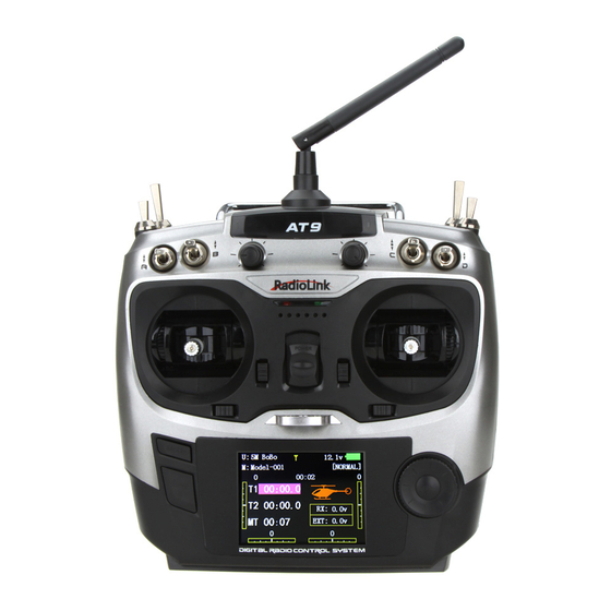
As shown below, home screen will display plane type and throttle pitch: ILLUST: displays the illustration of helicopter in the home screen. (Default) THR/PIT: displays the current throttle and pitch position in the home screen. Step to change plane type image to thr/pit: under model type helicopter, enter basic menu, choose MODEL TYPE, and enter HOME DISP, press PUSH, then DIAL to THR/PIT, then press PUSH. -
Page 21: Trim
THROTTLE DELAY. Goals Steps Inputs for 1s.(If ADVANCE, again) Open END POINT function Decrease the flap servo to END POINT,PUSH throw in the upward Choose proper channel and move direction to 5% to allow stick or Knob in direction you trimming of level flight to FLAP,PUSH,... -
Page 22: Sub Trim
SUB-TRIM: makes small changes or corrections to the neutral position of each servo. Range is -120 to +120, with 0 setting, the default, being no SUB-TRIM. We recommend that you center the digital trims before making SUB-TRIM changes, and that you try to keep all of the SUB-TRIM values as small as possible. -
Page 23: Dual/Triple Rates And Exponential (D/R,Exp)
Goals Steps Inputs for 1s .(If ADVANCE again) Open REVERSE function to REVERSE, PUSH. Revers the direction to REV,’Are you sure? displays Choose proper channel and to ELEV, of the elevator set direction(Ex:ELEV REV)] for 1s。 servo. Close 2.3.7 Dual/triple rates and exponential (D/R,EXP) Dual/Triple Rates: reduce/increase the servo travel by flipping a switch, or (ACRO GLID) they can be engaged by any stick position. - Page 24 • Range: 0 - 140% (0 setting would deactivate the control completely.) Initial value=100% • Adjustable for each direction (ACRO/ GLID) (ie. Up/down, left/right) (Ex: Most models fly upright without any elevator trim, but require some down elevator when inverted just to maintain level flight. By increasing the down travel by the amount required to hold the model inverted, the model now has equal travel available from level upright or level inverted.
-
Page 25: Throttle Cut
to SW,PUSH. to Cond. Optional:assign dual rates to Repeat steps above to adjust for each condition. have one for each condition. Goals Steps Inputs Open D/R,EXP for 1s to BASIC( to D/R,EXP,PUSH. Choose channel to change to CH,PUSH, to AILE,PUSH (Ex:aileron is already selected) Optional:Change switch position. - Page 26 (with THROTTLE STICK at idle). The movement is largest at idle and disappears at high throttle to avoid accidental dead sticks. In HELI, there is an additional setting. The switch's location and directio must be chosen. It defaults to NULL to avoid accidentally assigning it to a switch, which might result in an unintentional dead stick in flight.
-
Page 27: Idle Down (Acro Only)
HELICOPTER This function is used to stop engine after flight is finished. You can set engine powered on/ off, without shifting trim stick to power off and set again every time before flight. Throttle shut for helicopter includes THR ON/ OFF (position above idle down). Before resetting throttle cut, throttle stick must keep below setting point to avoid a sudden speeding up. -
Page 28: Auxiliary Channel Function (Including Channel 9-10 Controls)
【F/S】 1:AILE NOR 2:ELEV NOR 3:THRO 15% 4:RUDD NOR CH1:AILE 5:GEAR NOR NOR F/S 6:FLAP NOR 7:AUX1 NOR 8:AUX2 NOR Adjustability: •Each channel may be set independently. • The NOR (normal) setting holds the servo in its last commanded position. •... -
Page 29: Timer Submenu (Stopwatch Functions)
direction may be changed. • multiple channels may be assigned to the same switch, slider or knob; • channels set to "NULL" are only controlled by mixes. (Ex: utilizing 2 channels for 2 rudder servos. See mixes, p. 68.) • If GYRO SENSE, GOVERNOR, and THR-NEEDLE functions are activated, AUX-CH settings of related channels become invalid automatically. -
Page 30: Trainer
Adjustability: • Count down timer: starts from the chosen time, displays time remaining. If the time is exceeded, it continues to count below 0. • Count up timer: starts at 0 and displays the elapsed time up to 99 minutes 59 seconds. •... -
Page 31: Logic Switch Selection (Logic Sw)
• SWITCH: controlled by spring-loaded SWITCH H only. Not assignable. • Compatibility: The AT10 may be master or student with any Radiolink transmitter compatible with the cord. Simply plug the optional trainer cord (For AT10 series, sold separately) into the trainer connection on each transmitter, and follow the guidelines below. -
Page 32: Servo Display And Cycle Submenu
Adjustability: • Three logic switches can be used. (LSW1, LSW2, and LSW3 ) • SW(1): Any SWICH A-H or THRSTKS, SW(2): Any SWICH A-H • Switch position (POSI) • Logic mode: AND or OR (MODE) 2.3.15 SERVO display and cycle submenu: Displays radio's output to channels 1-10. - Page 33 Find telemetry information: under BASIC MENU, select RECEIVE, press PUSH to enter, you can find the telemetry info, shown as below. RX is receiver voltage, EXT is external voltage. Also temperature and engine speed (EXT, TEMPERATURE, RPM, and GPS all need telemetry sensor). RSSI is signal strength, NULL is for no signal, and 0 is for max.
-
Page 34: Part 3. Acro Advance Menu Functions
Part 3. ACRO ADVANCE MENU FUNCTIONS 3.1 AIRPLANE WING TYPES (ACRO/GLID): There are 3 basic wing types in aircraft models: • Simple. Model uses one aileron servo (or multiple servos on a Y-harness into a single receiver channel) and has a tail. This is the default setup and requires no specialized wing programming. •... -
Page 35: Acro Advance Function Menu
channel CH6&5 Select AILE-2 and change to to AILE-2. to CH6&5 CH6&5. Allow twin aileron servo operatin with a 5-channel Close receiver. There are 4 basic tail types in aircraft models: • Simple. Model uses one elevator servo and one rudder servo (or multiple servos on a Y-harness). This is the default. -
Page 36: Program Mix
• THROTTLE DELAY mixing is a pre-programmed delay mix that slows down the response of the CH3 servo. Next, we'll get an in-depth look at some pre-programmed mixes (mixes whose channels are predefined for simplicity) we’ve not covered yet, and last, look at the fully-programmable mix types. 3.3.1 Program MIX AT9 contains four separate linear programmable mixes. - Page 37 MASTER SLAVE LINK TRIM SWITCH POSITION RATE OFFSET VR(D) THRO NULL •Slave: the controlled channel. The channel is moved automatically in response to the movement of the master channel. The second channel is in a mix’s name (i.e. aileron-to-rudder). •Link: Link this programmable mix with other mixes. Ex: PMIX FLAP-ELEVATOR mixing to correct for ballooning when flaps are lowered, but model has a V-tail.
-
Page 38: Curve Programmable Mixes (Prog.mix5-8)(Heli: Prog.mix5-6 )
Optional:set Master as OFST or to Master,PUSH, todesiredchoice VR(A-E) Set LINK and TRIM as needed. to LINK,PUSH , to DWON Assign SWITCH and position. to SW,PUSH, to SwC (Ex:change from E to C,Down) to POSI,PUSH to DOWN to SW ,PUSH to STK-THR Optional:set switch to STK-THR to activate mix with THROTTLE... -
Page 39: Flaperon (Acro/Glid 1A+1F )
• ACRO/GLID Defaults: The 4 programmable curves mixes default to the most frequent choices, but can be set to any channel. • PROG.MIX5 rudder-to-aileron for roll coupling compensation (GLID mixes default to aileron-to-elev.) • PROG.MIX6 rudder-to-aileron for roll coupling compensation (GLID mixes default to aileron-to-elev.) •... -
Page 40: Flap-Trim
The FLAPERON mixing function uses one servo on each of the two ailerons, and uses them for both aileron and flap function. For flap effect, the ailerons raise/lower simultaneously. Of course, aileron function (moving in opposite directions) is also performed. Note: When changing the polarity of a rate, "change rate dir?"... -
Page 41: Aile Diff (Acro/ Glid 2A+1F/ Glid 2A+2F)
ACRO GLID FLAP-TRIM assigns the primary flaperon control [defaults to VR(A)] to allow trimming in flight of the flap action of flaperons. Note: Even if FLAP-TRIM is made active with AIL-DIFF, it will not have any effect. The ONLY function that allows control of the ailerons as flaps in the AIL-DIFF configuration is AIRBRAKE. Most modelers use AIRBRAKE, or programmable mixes, to move the flaps to a specified position via movement of a switch. -
Page 42: Air Break (Acro/ Glid)
Activate twin aileron to BASIC menu, again to ADVANCE Open the FLAPERON. servosusing AILE-DIFF. to AILE-DIFF .PUSH. Note that the function defaults to no difference in Activate the function. to MIX,PUSH. to ACT down travel vs. up travel. If Optional:adjust the up/down you want differential travel, to AILE1 AILERON STICK. -
Page 43: Elev-Flap Mixing (Acro/Glid)
CH1 and CH6. The flap choice has no effect on the flaperons. • If AIL-DIFF is active, then CH1 and CH7 may be independently adjusted. • Normally both ailerons are raised equally in AIRBRAKE, and the elevator motion is set to maintain trim when the ailerons rise. -
Page 44: Dual Elevator Servos (With A Rudder) (Ailevator) (Acro)
Adjustability: • Rate: -100% (full up flap) to +100% (full down flap), with a default of +50% (one-half of the flap range is achieved when the ELEVATOR STICK is pulled to provide full up elevator.) • Switch: fully assignable. Also LOGIC SW (Lsw1 to 3) may be assigned. IF you set it to NULL, the mix does not work. -
Page 45: Snap Rolls (Acro)
Once AILEVATOR is activated, unless you zero out the aileron figures (see below), any time you move your ailerons or any programming moves your ailerons (ie. RUDDER-AILERON mixing), the radio automatically commands both elevator servos to also operate as ailerons. To deactivate this action, simply set the 2 aileron travel settings to 0 in the AILEVATOR function. -
Page 46: V-Tail (Acro/ Glid)
• ON: the safety mechanism is activated when the landing gear SWITCH is in the same position as at the time this feature is changed to ON. Snap rolls will not be commanded even if the snap roll SWITCH is turned on with the gear SWITCH in this position. -
Page 47: Elevon
large value of travel is specified, when the sticks are moved at the same time, the controls may bind or run out of travel. Decrease the travel until no binding occurs. Adjustability: • Requires use of CH2 and CH4. • Independently adjustable travels allow for differences in servo travels. •... -
Page 48: Gyro Sense
Adjustability: • Plug the gyro's sensitivity adjustment to channel 5, 7, or 8 of the receiver. (selectable) • Full switch assignable (SWITCH A-H) • Each rate setting may be set from 0 to NOR100% or AVC100% gain. NOR: GY mode gain. AVC: STD mode gain •... -
Page 49: Thr-Delay (Acro)
The THR-DELAY function is used to slow the response of the throttle servo to simulate the slow response of a turbine engine. A 40% delay setting corresponds to about a one-second delay, while a 100% delay takes about eight seconds to respond. This function may also be used to create a “slowed servo” on a channel other than throttle. -
Page 50: Throttle-Needle Mixing (Acro/ Heli)
Optional: delete the curve to P3 (-stk-). for 1sec.to delete the curve point. point.And return the curve to P3 (-stk-), for 1sec.to return point.(Ex:point 3) Adjust the next point. Repeat as needed. Close 3.3.15 THROTTLE-NEEDLE mixing (ACRO/ HELI): ACRO HELI THROTTLE-NEEDLE is a pre-programmed mix that automatically moves an in-flight mixture servo (CH8) in response to the THROTTLE STICK inputs for perfect engine turning at all throttle settings. - Page 51 to PIONT. Throttle Stick to P 1, to40%, Adjust the travels as needed to match your engine by slowly Throttle Stick to P 2, to 45%, moving the stick to each 5 points, then adjusting the percentage at Throttle Stick to P 3, to 65%,...
-
Page 52: Part 4 Glider Model Functions
PART 4 GLIDER MODEL FUNCTIONS Please note that nearly all of the BASIC menu functions are the same for airplane (ACRO setup), sailplane (GLID 1A+1F/ 2A+1F/ 2A+2F setups), and helicopter (HELI setups). The features that are identical refer back to the ACRO chapter. The glider BASIC menu includes MOTOR CUT and does not include IDLE-DOWN or THR-CUT. -
Page 53: Set Glid Type
In the BASIC menu, open to REVERSE. REVERSE. REVERSE servos as needed for Choose desired servo and to 4.RUDD, REV is highlighted. for 1 proper control operation. reverse its direction of sec. ‘Are you sure?’Displays. to confirm. travel. (Ex:reverse rudder servo.) To BASIC menu. -
Page 54: Glid Advance Menu
Before doing anything else to set up a glider or sailplane, first you must decide which MODEL TYPE best fits your aircraft. • GLID(1A+1F): The GLID (1A+1F) MODEL TYPE is intended for sailplanes with one or two aileron servos (or none), and a single flap servo (or two connected with a y-connector). This TYPE is meant to be a very simplistic version to set up a basic glider without a lot of added features. -
Page 55: Flaperon (Glid 1A+1F, Find In Acro Function Menu 3.3.3)
4.3.1 AILE DIFF (FIND IN ACRO FUNCTION MENU 3.3.5) 4.3.2 FLAPERON (GLID 1A+1F, FIND IN ACRO FUNCTION MENU 3.3.3) 4.3.3 V-TAIL (FIND IN ACRO FUNCTION MENU 3.3.10) 4.3.4 OFFSET (GLID 2A+2F): Additional flight conditions are available specifically for sailplanes. These additional flight conditions contain different offset trims to make the sailplane perform certain maneuvers more easily. -
Page 56: Chamber-Flp
Close 4.3.5 START DELAY (GLID 1A+1F only): START DELAY automatically switch the offset trims (OFFSET) from the START condition's trims to the normal condition’s trims after proceeding the delay time (max.10sec.) which is set by the -dly- item when activating the START condition. (It is convenient for hand launch glider.) Note: The same delay amount for elevator and rudder is recommended when using V-tail function. -
Page 57: Camber Mixing
Note: When changing the polarity of a rate, "change rate dir?" is displayed for a check. Please set up after pressing DIAL for 1 second and canceling an alarm display. Goals Steps Inputs to BASIC . again to ADVANCE Open the CAMBER FLAP to CAMBER-FLP, function. -
Page 58: Butterfly (Crow) Mixing
to PRE , VrA to desired Set the reference point. point for 1 sec. Close 4.3.8 BUTTERFLY (crow) mixing BUTTERFLY simultaneously moves the flaps, twin ailerons and elevator, and is usually used to make steep descents or to limit increases in airspeed in dives. Separate two BUTTERFLY settings are available. (CRI1/CRI2) ADJUSTABILITY: •... -
Page 59: Aile/ Rudd Mix
to BASIC . again to ADVANCE Open the BUTTERFLY function to BUTTERFLY, Activate BUTTERFLY. Adjust the aileron and flap travel to 75% SWA to UP position Activate the function to MIX to OFF , Elevator setting are adjustable in the Adjust the travels as B.FLY-ELE. -
Page 60: Spoiler Mix (Glid)
This pre-programmed mix is used to create full span aileron action on a glider with 4wing servos. This increases the roll rate and decreases induced drag. For normal flying, a value of about 50% is often used. For slope racing or F3B models in speed runs, you may wish to use a larger value approaching 100%. -
Page 61: Flap-Trim (See Glid 3.3.4)
Adjust the spoiler Activate the function. to MIX , to ON. servo position to 60% Assign the SPO2-CH.(Ex: to –SPO2- CH to CH3, , CH3) Adjust the spoiler servo to –SPO1-POSI to -50%, to 60%, , position. (Ex: to –SPO2-POSI to +50%, to 60%, ,... -
Page 62: Part. 5 Helicopter Model Functions
Part. 5 HELICOPTER MODEL FUNCTIONS Please note that nearly all of the BASIC menu functions are the same for airplane (ACRO setup), sailplane (GLID setups), and helicopter (HELI) setups. The features that are identical refer back to the ACRO chapter. 5.1 BASIC SETTING WITH HELICOPTER This guideline is intended to help you set up a basic (H-1) heli, to get acquainted with the radio, to give you a jump start on using your new radio, and to give you some ideas and direction on how to do even more... - Page 63 Input name. to change the first character. Close the submenu when When proper character is display. to next. Repeat. done. Goals Steps Inputs Reverse servos as needed for In BASIC menu, open for 1s to BASIC.(If proper control operation.Ex: Reverse. ADVANCE again) .
-
Page 64: Heli-Specific Basic Menu Functions
With radio on, move helicopter’s tail to the right by hand. The gyro should give right rudder input (leading edge of the tail rotor Confirm gyro direction. blades move left). If the gyro gives the opposite input, reverse direction on the gyro unit itself. Goals Steps Inputs... -
Page 65: Swash Plate Types
5.2.1 Swash Plate Types Goals Steps Inputs Confirm you are using On home screen,check model name and # on top left. If it is the proper model not the correct model (Ex:3) see MODEL SEL. Change the model memory(Ex:3) type and swashplate of model#3 from for 1s to BASIC.(If ADVANCE again) . -
Page 66: Heli-Specific Advance Menu Functions
Swash plate function rate settings (SWASH AFR) reduce/increase/reverse the rate (travel) of the aileron, elevator (except H-2) and collective pitch functions, adjusting or reversing the motion of all servos involved in that function, only when using that function. Since these types utilize multiple servos together to create the controls, simply adjusting a servo's REVERSE or END POINT would not properly correct the travel of any one control. -
Page 67: Revo Mix
• Normal: Collective pitch curve that results in points 1, 4 and 7 providing .4, +5, (+8 to +10)* degrees pitch. A throttle curve setting of 0, 25, 36, 50, 62.5, 75, 100%. • Idle-ups 1 & 2: Idle-ups 1 and 2 are typically the same except for the gyro settings, with one being heading-hold/AVCS and the other being normal mode. - Page 68 Clockwise rotation: -20, -10, 0, +10, +20% from low throttle to high. Counterclockwise rotation: +20, +10, 0, -10, -20% from low throttle to high. Adjust to the actual values that work best for your model. Revo. Curves for idle-ups are often v-shaped to provide proper rudder input with negative pitch and increased throttle during inverted flight.(Rudder is needed to counter the reaction whenever there is increased torque.
-
Page 69: Gyro Sense
h o v e r . L a n d / s h u t e n g i n e Adjust Repeat above as needed PIT-CURV/NOR o f f . A d j u s t t hrottle curves and rudder trim. -
Page 70: Throttle Hold
Close 5.3.4 THROTTLE HOLD This function holds the engine in the idling position and disengages it from the THROTTLE STICK when SWITCH AT9 is moved. It is commonly used to practice auto-rotation. Prior to setting up THR-HOLD, hook up the throttle linkage so that the carburetor is opened fully at high throttle, then use the digital trim to adjust the engine idle position. -
Page 71: High/Low Pitch (Hi/Lo-Pit)
accommodated. • Both adjustments may be inhibited if not desired. • Both adjustments may also be set to NULL, temporarily turning off the knob but maintaining the last memorized setting. • Adjustments may be memorized and then the knobs returned to center point to use that amount of adjustment, allows easy use of the trimming knobs for multiple models. -
Page 72: Offset
Select the idle-up 1 condition to COND , to IDL1 Set the rate(Ex:80%) to 80% to HI-PIT , Optional:Change which knob adjusts high pitch curve. to VR to desired knob and direction. , Close 5.3.7 OFFSET Optional separate trims in addition to those for the normal condition. This function is used to automatically change the trim of a helicopter, for example, when transitioned from hover to flying at high speed. -
Page 73: Delay
Adjust trim settings as needed. to RUDD to +8%, , (Ex:rudder to +8% .) Close menus and confirm E (AT9) from NORMALto IDL2.Check the slowed transitions. changes of rudder trim. 5.3.8 DELAY: The Delay function provides a smooth transition between the trim positions whenever OFFSET, REVO, MIXING, or THROTTLE HOLD functions are turned on and off. - Page 74 ADJUSTABILITY: • On/off may be separate from speed switching by plugging governor on/off into CH8 and changing CUT-CH setting. • If using separate on/off, switch assignment is totally adjustable. Be careful not assign governor off to a condition switch if you want the governor to function in that condition. •...
-
Page 75: Throttle Mixing (Throttle Mix)
governor settings Activate the function. to MIX to ACT. , automatically when changing Opt ion al : chang e cut- of f conditions. Consider setting the to -cut- CH: to+CH8, channe lto channel 8 and , battery Fail Safe settings and assign switch and direction other helpful functions on the to -cut-SW... -
Page 76: Throttle Needle (See Acro Menu 3.3.15)
• Initial: 100% • adjusting range: 0-200% Goals Steps Inputs to BASIC menu, again to Open SWASH-RING To prevent damaging the swash ADVANCE function. linkage by simultaneous operation of to SWASH-RING the ailerons and elevators, set the limit point where swash throw stops. Activate the function. - Page 77 • SWITCH G (AT9) or E (AT9) is programmed for normal (NORM), idle-up 1 (IDLE-UP1), and idle-up 2 (IDLE-UP2) curves, adjustable in CONDITION SELECT (IDLE-UP1/2, IDLE-UP3 items). (IDLE-UP1/2 3-position type switch only, IDL3 2-position type switch only) • Activated with the throttle curve for that condition in THR-CURVE. •...
-
Page 78: Part 6. Aircraft Functions
Part 6. AIRCRAFT FUNCTIONS AIRCRAFT menu is the most differ between AT9 and AT10. The menu makes it easier to fly multi copters. The basic function menu is same like ACRO, GLID and HELI, please find the detail in the former chapters. Now let’s start the basic setting, take a quad copter for example: Goals Steps... -
Page 79: Aircraft Basic Menu
set the first (Ex:low) rate to D/R SwA to down,repeat to set low rate. throws and exponential. Optional: change dual rate to SW SwG, SwG to center position. , switch assignment. Repeat steps above to set 3 rate. On BASIC menu, then to AUX-CH, open AUX-CH function. -
Page 80: Aux Channel Setting
6.1.2 AUX Channel setting AUX channel for aircraft is channel 6 to 10, same like ACRO, GLID and HELI, to set auxiliary channel. CH5 is special for ATTITUDE, enter CH5 and press PUSH for ATTITUDE. Select 3-section and 2-section switch to get 6 different attitudes. By DIAL set 6 different rates according to the attitudes. 6.2 ADVANCE MENU FOR AIRCRAFT 6.2.1 ATTITUDE There are 6 different attitude modes for aircraft: NORMAL, ATTI, GPS, HOVER, F/S and AUX.